EP1024269A2 - Electronic throttle control system - Google Patents
Electronic throttle control system Download PDFInfo
- Publication number
- EP1024269A2 EP1024269A2 EP00300115A EP00300115A EP1024269A2 EP 1024269 A2 EP1024269 A2 EP 1024269A2 EP 00300115 A EP00300115 A EP 00300115A EP 00300115 A EP00300115 A EP 00300115A EP 1024269 A2 EP1024269 A2 EP 1024269A2
- Authority
- EP
- European Patent Office
- Prior art keywords
- gear
- throttle
- spring
- valve
- valve assembly
- Prior art date
- Legal status (The legal status is an assumption and is not a legal conclusion. Google has not performed a legal analysis and makes no representation as to the accuracy of the status listed.)
- Withdrawn
Links
Images



Classifications
-
- F—MECHANICAL ENGINEERING; LIGHTING; HEATING; WEAPONS; BLASTING
- F02—COMBUSTION ENGINES; HOT-GAS OR COMBUSTION-PRODUCT ENGINE PLANTS
- F02D—CONTROLLING COMBUSTION ENGINES
- F02D9/00—Controlling engines by throttling air or fuel-and-air induction conduits or exhaust conduits
- F02D9/02—Controlling engines by throttling air or fuel-and-air induction conduits or exhaust conduits concerning induction conduits
-
- F—MECHANICAL ENGINEERING; LIGHTING; HEATING; WEAPONS; BLASTING
- F02—COMBUSTION ENGINES; HOT-GAS OR COMBUSTION-PRODUCT ENGINE PLANTS
- F02D—CONTROLLING COMBUSTION ENGINES
- F02D11/00—Arrangements for, or adaptations to, non-automatic engine control initiation means, e.g. operator initiated
- F02D11/06—Arrangements for, or adaptations to, non-automatic engine control initiation means, e.g. operator initiated characterised by non-mechanical control linkages, e.g. fluid control linkages or by control linkages with power drive or assistance
- F02D11/10—Arrangements for, or adaptations to, non-automatic engine control initiation means, e.g. operator initiated characterised by non-mechanical control linkages, e.g. fluid control linkages or by control linkages with power drive or assistance of the electric type
- F02D11/107—Safety-related aspects
-
- F—MECHANICAL ENGINEERING; LIGHTING; HEATING; WEAPONS; BLASTING
- F16—ENGINEERING ELEMENTS AND UNITS; GENERAL MEASURES FOR PRODUCING AND MAINTAINING EFFECTIVE FUNCTIONING OF MACHINES OR INSTALLATIONS; THERMAL INSULATION IN GENERAL
- F16K—VALVES; TAPS; COCKS; ACTUATING-FLOATS; DEVICES FOR VENTING OR AERATING
- F16K31/00—Actuating devices; Operating means; Releasing devices
- F16K31/02—Actuating devices; Operating means; Releasing devices electric; magnetic
- F16K31/04—Actuating devices; Operating means; Releasing devices electric; magnetic using a motor
- F16K31/041—Actuating devices; Operating means; Releasing devices electric; magnetic using a motor for rotating valves
- F16K31/043—Actuating devices; Operating means; Releasing devices electric; magnetic using a motor for rotating valves characterised by mechanical means between the motor and the valve, e.g. lost motion means reducing backlash, clutches, brakes or return means
-
- F—MECHANICAL ENGINEERING; LIGHTING; HEATING; WEAPONS; BLASTING
- F02—COMBUSTION ENGINES; HOT-GAS OR COMBUSTION-PRODUCT ENGINE PLANTS
- F02D—CONTROLLING COMBUSTION ENGINES
- F02D9/00—Controlling engines by throttling air or fuel-and-air induction conduits or exhaust conduits
- F02D9/02—Controlling engines by throttling air or fuel-and-air induction conduits or exhaust conduits concerning induction conduits
- F02D2009/0201—Arrangements; Control features; Details thereof
- F02D2009/0261—Arrangements; Control features; Details thereof having a specially shaped transmission member, e.g. a cam, specially toothed gears, with a clutch
-
- F—MECHANICAL ENGINEERING; LIGHTING; HEATING; WEAPONS; BLASTING
- F02—COMBUSTION ENGINES; HOT-GAS OR COMBUSTION-PRODUCT ENGINE PLANTS
- F02D—CONTROLLING COMBUSTION ENGINES
- F02D9/00—Controlling engines by throttling air or fuel-and-air induction conduits or exhaust conduits
- F02D9/02—Controlling engines by throttling air or fuel-and-air induction conduits or exhaust conduits concerning induction conduits
- F02D2009/0201—Arrangements; Control features; Details thereof
- F02D2009/0269—Throttle closing springs; Acting of throttle closing springs on the throttle shaft
-
- F—MECHANICAL ENGINEERING; LIGHTING; HEATING; WEAPONS; BLASTING
- F02—COMBUSTION ENGINES; HOT-GAS OR COMBUSTION-PRODUCT ENGINE PLANTS
- F02D—CONTROLLING COMBUSTION ENGINES
- F02D9/00—Controlling engines by throttling air or fuel-and-air induction conduits or exhaust conduits
- F02D9/02—Controlling engines by throttling air or fuel-and-air induction conduits or exhaust conduits concerning induction conduits
- F02D2009/0201—Arrangements; Control features; Details thereof
- F02D2009/0277—Fail-safe mechanisms, e.g. with limp-home feature, to close throttle if actuator fails, or if control cable sticks or breaks
Definitions
- This invention relates to electronic valve control systems and more particularly to an electronic throttle control system for an internal combustion engine.
- Valve assemblies for engines and related systems typically utilise rotatable valve members in fluid flow passageways to assist in regulating fluid flow through them.
- throttle valve members are positioned in air induction passageways into internal combustion engines.
- the valve assemblies are controlled either mechanically or electronically and utilise a mechanism which directly operates the valve member.
- Known electronic throttle control assemblies utilise a plurality of components which typically are difficult and time consuming to assemble together. Also, the throttle or valve plate is positioned on a throttle body shaft which often experiences undesirable axial or radial movement which can adversely affect the operation of the valve assembly.
- the present invention provides an electronic throttle control assembly having a housing with a motor, a gear train and throttle valve.
- a throttle plate is positioned on a throttle shaft and the plate and shaft are positioned in the engine air induction passageway, such that the throttle plate regulates airflow into the engine.
- the operation of the throttle valve is accomplished by a gear train assembly driven by a DC motor.
- the motor is regulated by the electronic control unit of the vehicle which in turn is responsive to the input of the vehicle operator or driver.
- a throttle position sensor is included in a housing cover and feeds back the position of the throttle plate to the electronic control unit.
- the throttle body shaft is held in the throttle valve section of the control assembly housing by bearing members. Axial and radial movement (“play") of the throttle body shaft is prevented by an axial clip member which is secured on one end of the shaft.
- a gear connected to the motor operates an intermediate gear, which in turn operates a sector gear which is connected to the throttle body shaft.
- the sector gear is biased by a spring member in both the open and closed positions of the throttle valve.
- a default lever is operably attached to the spring member and operated by a boss attached to the intermediate gear.
- the bias of the spring member in combination with the default lever operates to open the throttle valve in the event of failure of the electronic system.
- Figure 1-3 illustrate one embodiment of an electronic throttle control assembly in accordance with the present invention.
- Figure 1 illustrates the assembly 20 in its assembled form
- Figure 2 illustrates the components of the assembly in an exploded condition
- Figure 3 is a cross-sectional view of the assembly 20 as shown in Figure 1 (without the cover).
- the electronic throttle control assembly 20 includes a housing or body member 22 and a cover member 24.
- the housing 22 includes a motor section 26, a throttle valve section 28, and a gear train section 30.
- the cover member 24 includes the throttle position sensor (TPS) 32, together with related electronics, which reads or "senses" the position of the throttle valve and transmits it to the electronic control unit (not shown) of the vehicle.
- TPS throttle position sensor
- an electrical connector 25 is positioned on the cover 24.
- the connector preferably has six contacts: two to the motor which regulates the position of the throttle valve; and four to the TPS and related electronics.
- the electronic control unit sends a signal to the electronics in the electronic throttle control assembly 20 which operates the motor which in turn operates the gear train and adjusts the position of the throttle valve.
- the throttle valve is positioned in the main air passageway 72 from the air intake inside the engine compartment to the internal combustion engine. The throttle valve thus regulates the airflow to the internal combustion engine.
- the precise position of the throttle valve in the airflow passageway is sensed by the TPS and relayed or fed back to the ECU in order to confirm or adjust the desired throttle valve setting.
- the cover member can be attached to the body member 22 in any conventional manner, but preferably is connected by a snap tab mechanism.
- a series of openings 120 are provided in the cover member for mating with a series of tab members 122 on the outside of the gear section 30 of the housing 22.
- an appropriate gasket or sealing member (not shown) is preferably positioned between the cover member and the housing in order to protect the gear train and TPS from dirt, moisture and other environmental conditions.
- the electronic throttle control assembly 20 When the electronic throttle control assembly 20 is utilised, it is positioned in the engine compartment of the vehicle and bolted or otherwise securely fastened to the vehicle.
- a plurality of holes 21 are provided in the housing.
- the motor 40 is a thirteen volt DC motor.
- the motor 40 is connected to a mounting plate 42 which is bolted or otherwise securely fastened to the body member 22 by a plurality of bolts, screws, or other fasteners 44.
- the plate 42 also has a pair of contacts (not shown) which electrically connect the electronics in the cover member 24 to the motor 40.
- the motor 40 has a shaft 46 on which a spur gear 48 is positioned.
- the gear 48 has a plurality of teeth 47 which mesh with and rotate adjacent gears, as described below.
- the throttle plate 60 is secured to a throttle body shaft 62 which in turn is positioned in the throttle section 28 of the body member or housing 22.
- the throttle plate 60 is secured to the throttle body shaft 62 by a plurality of small fasteners or plate screws 64.
- the throttle shaft 62 is positioned in a bore or channel 70 in the throttle section of the body member 22.
- the bore 70 is transverse to the axis of the air flow passageway 72.
- Throttle shaft 62 has an O-ring channel or groove 74, a pair of flats or recesses 76 at the upper end for connection to one of the gears (as explained below), a pair of openings 78 for positioning of the plate screws therethrough, an axial or longitudinally extending slot 80 for positioning of the throttle plate 60 therein, and a pair of flats or recesses 82 at the lower end for use in assembling and positioning the throttle valve.
- the flats 82 are utilised to rotate the throttle shaft 62 during assembly of the throttle plate and also during orientation and set-up of the throttle positioning sensor (TPS) mechanism.
- An O-ring 84 is positioned in the channel 72 on the throttle shaft. The O-ring 84 provides a seal between the air in the air flow passageway and the gear train components and electronics in the cover.
- the throttle body shaft 62 is first positioned in the bore 70 and rotated in order to allow the plate 60 to be positioned in slot 80.
- the throttle body shaft 62 is then turned approximately 90 degrees in order to allow the throttle plate screws 64 to be secured through the shaft and plate, thereby securely affixing the plate to the shaft.
- a pair of bearings 86 and 88 are provided to allow the throttle body shaft to rotate freely in the housing.
- the bearings 86 and 88 are conventional ball-bearing members with pairs of races separated by small ball-bearings.
- an axial spring clip member 90 is secured to the lower end of the shaft.
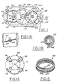
- the spring clip 90 is also shown in more detail in Figures 2, 12 and 14.
- the spring clip 90 has a central annular disc 91, a plurality of inner spring tab members 92 and a plurality of outer spring tab members 94.
- the spring clip member 90 is preferably made of a spring steel material.
- the tab members 92 securely hold the axial spring clip member 90 in place on the throttle body shaft 62; tab members 94 securely hold the throttle body shaft 62 securely in position in the throttle section 28 of the body or housing member 22.
- the outer tab members 94 are securely wedged against the inside surface of cavity 96 on the lower end of the throttle section 28, while the inner tab members 92 are wedged against the surface of the throttle shaft 62.
- the axial spring clip member 90 eliminates axial or longitudinal movement (i.e., "play") of the throttle body shaft 62 inside of the throttle section.
- the upper end of the throttle body shaft 62 is secured against axial movement by the lower end of the moulded sector gear (as shown in Figures 3 and as described in more detail below), while the axial spring clip 90 securely and tightly affixes the lower end of the throttle body shaft against axial movement.
- the clip member 90 is pushed or forced onto the shaft 62 until it contacts the inner race of bearing 88.
- the clip member 90 is installed with a predetermined load.
- the load pre-loads both of the bearings 86 and 88 and eliminates axial movement of the shaft in the assembly 22.
- the pre-load on the bearings also eliminates any radial movement or "slop" between the inner and outer races of the bearings.
- the elimination of the axial and radial movement of the throttle shaft in the assembly improves the quality of the feedback signal provided by the TPS to the ECU.
- the movement of the throttle body shaft and hence the throttle plate will be more accurately and precisely sensed and read by the TPS and thus more accurately and precisely relayed to the EPU.
- the pre-loading of the bearing members also eliminates the burnishing of the ball-bearing members in the bearings during normal vehicle operation.
- an end cap member or plug member 98 is positioned on the end of the cavity 96. This protects the lower end of the shaft from moisture, dirt and other environmental conditions which might adversely affect the operation of the throttle valve.
- the gear assembly or gear train used with the electronic control assembly 20 in accordance with the present invention is generally referred to by the numeral 100 in the drawings.
- the gear train mechanism 100 includes spur gear 48 attached to motor 40, an intermediate gear member 102 (Figure 4), and a sector gear member 104 ( Figure 7).
- the intermediate gear 102 is mounted on a shaft member 106 which is secured to the housing or body member 22 (see Figures 1-3).
- the intermediate gear 102 can freely rotate on shaft 106.
- the intermediate gear 102 has a first series of gear teeth 108 on a first section 109 and a second series of gear teeth 110 on a second section 111.
- a boss 130 which is used to actuate the default lever (as explained below) is positioned on the first section 109.
- the gear teeth 108 on gear 102 are positioned to mesh with the gear teeth 47 on the motor driven gear 48, while the gear teeth 110 are positioned and adapted for mating with the gear teeth 112 on the sector gear 104.
- the teeth 112 on gear 104 are only provided on a portion or sector of the outside circumference of the gear member.
- All of the gear members 48, 102 and 104 are preferably made of a plastic material, such as nylon, although they can be made of any other comparable material, or metal, which has equivalent durability and function.
- the sector gear 104 is preferably moulded onto the end 63 of the throttle body shaft 62.
- the recesses 76 are provided in the shaft 62 which allow the sector gear to be integrally moulded to the shaft and be permanently affixed thereto.
- the lower end 105 of the sector gear is preferably formed such that it contacts bearing 86, thus helping to hold throttle body shaft in axial position.
- the sector gear 104 has a central portion or member 114 which extends above the gear train 100 and either communicates with or makes direct contact with the throttle position sensor (TPS) mechanism 32 in the cover member 24.
- TPS throttle position sensor
- the central member 114 on the sector gear 104 can be positioned in a mating hub (not shown) inside the cover member 24, which then by rotation or movement would be able to detect the movement and resultant position of the throttle valve plate 60.
- a small (rectangular) magnet 113 is positioned on the upper end of the central member 114. The TPS could then be set up to read the direction of the magnetic field emanating from the magnet and thus read or sense the rotational movement of the throttle body shaft and valve plate in order to feedback the position to the EPU.
- a signal from the EPU is sent to the motor 40 through the electronics module in the cover 24.
- the motor rotates spur gear 48 which then rotates intermediate gear 102.
- the rotation of gear 102 in turn rotates sector gear 104 and also throttle body shaft 62, which is directly attached to gear 104.
- the rotation of shaft 62 accurately positions the valve plate 62 in the passageway 72 and allows the requisite and necessary air flow into the engine in response to movement of the accelerator.
- the present invention also has a fail-safe mechanism which allows the throttle valve plate to remain open in the event of a failure of the electronics system in the throttle control mechanism or in the entire vehicle.
- a spring member 132 and a default lever member 134 are utilised in combination with the sector gear member 104.
- the combination of sector gear member 104, spring member 132, and default lever member 134 are joined together to form a sub-assembly 140, as shown in Figure 8.
- This sub-assembly, in combination with ridge wall or stop member 143 in the gear train section 30 of the housing 22 act together to limit the operation of the valve plate member and control the operation of the fail-safe mechanism.
- the default lever member 134 has a circular central collar member 136 on one side with a central opening 138 therein.
- the collar member 136 also has an opening or slot 142 which is adapted to mate with one end, particularly the inner end 144, of the spring member 132.
- the default lever member 134 also has a stop arm member 146, a driver arm member 148 and a pair of spring control arms 150 and 152.
- the control arms 150 and 152 rest on top of the spring member and act to hold it in place in the gear 104.
- the spring control arm 150 also has a snap-fit finger member 154 on the end thereof which is utilised to help hold the sub-assembly 140 together, as described below.
- the central opening 138 of the default lever member 134 is positioned over the central member 114 of the sector gear 104. This allows the default lever 134 to rotate freely relative to the sector gear member.
- the spring member 132 is joined together with the default lever member 134.
- the spring member 132 is positioned on the bottom of the default lever member 134 around the collar member 136, with the inner end 144 of the spring member 132 positioned in slot 142.
- the spring member 132 is then compressed sufficiently to allow the spring member to fit within the recessed area or cavity 160 on one side of the sector gear member 104 (see Figure 7).
- the outer end 162 of the spring member is positioned in the opening or slot 164 in the sector gear member between the sector of gear teeth 112 and the shoulder or tab member 166.
- the assembly of the three components of the gear train and fail-safe mechanisms into the electronic throttle control assembly is faster and easier.
- the members 132, 134 and 104 are first assembled together to form sub-assembly 140 which is then positioned as a unit or sub-assembly in the gear train cavity 30.
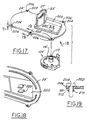
- the spring member 180 is a helical torsion spring member and has a pair of ends 182 and 184.
- the torsion spring member 180 and be used in place of the helical "clock-type" spring member 132 described above.
- the ends 182 and 184 of the spring member 180 correspond generally to the inner and outer ends 144 and 162, respectively, of spring member 132 and generally provide a similar function and purpose. In this regard, however, end 182 of spring member 180 is positioned on top of the default lever member 134, rather than being positioned inside the collar member.
- the other end 184 of the spring member 180 is positioned in the same slot or opening 164 in the sector gear member 104 as the end 162 of the spring member 132.
- the sector gear member 104 also has a stop shoulder or first positioner member 170 and a ramp stop or second positioner member 172.
- the two stops or positioner members are utilised in combination with the stop arm member 146 and driver member 148 on the default lever member 134, and with the spring member 132 and wall ridge 143, to provide a fail-safe mechanism for use with the electronic throttle control assembly in accordance with the present invention.
- the spring member 132 is positioned so that it is biased in both directions of rotation, and has a neutral or unbiased position when the throttle plate is at a slightly opened position (i.e., the "default position").
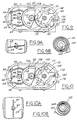
- the throttle plate 60 has a range of operation between a fully closed position ( Figure 9A) to a fully opened position ( Figure 10A).
- Figure 9A the air passageway 72 is completely blocked off.
- Figure 10A the throttle plate is positioned parallel with the airflow thus allowing a full compliment of air to pass through the passageway 72.
- the throttle plate 60 when the throttle plate 60 is in its fully closed position, it actually is positioned about 7°-10° from a position transverse to the air flow passageway axis. This allows better movement and ease of opening of the throttle valve member.
- the throttle valve plate member is in the default position, it is opened about 5°-10° from the throttle valve's closed position, or about 12°-20° from a position transverse to the axis of the air flow passageway.
- the two stops or positioner members 170 and 172 on the sector gear 104 are used in combination with the wall ridge 143 on the housing 22, to limit the range of motion of the throttle valve and ensure that it does not go past the fully open or fully closed positions.
- the second positioner member 172 is abutted against the wall stop 143 and prevented from opening any further (see Figure 10).
- the first positioner member 170 is abutted against the opposite side of wall stop 143, thus preventing the valve plate from attempting to close more tightly and perhaps wedging shut or adversely affecting further operation (see Figure 9).
- the throttle plate 60 In the fail-safe position of operation, the throttle plate 60 is at a slightly open position, as shown in Figure 11A. In such a position, the throttle valve allows some air to flow through the passageway 72, thus providing the engine with sufficient inlet air to allow the vehicle to "limp-home".
- the spring member 132 When the sub-assembly 140 is positioned in the gear section 30, the spring member 132 is positioned such that its inner end 144 is biased when the throttle plate is in its closed position, as shown in Figures 9A and 9B, while its outer end 162 is biased when the throttle plate is in its fully open position, as shown in Figures 10A and 10B. Thus, at all times except when the throttle valve is in the default open position, the spring member 132 is biased in one direction or the other during operation of the throttle control valve system. The force of the motor 40 acting through the gear train mechanism 100 overcomes the biasing forces provided by the spring member 132 and operates the control of the throttle valve plate 60.
Landscapes
- Engineering & Computer Science (AREA)
- General Engineering & Computer Science (AREA)
- Mechanical Engineering (AREA)
- Chemical & Material Sciences (AREA)
- Combustion & Propulsion (AREA)
- Control Of Throttle Valves Provided In The Intake System Or In The Exhaust System (AREA)
Abstract
Description
Claims (10)
- A valve assembly comprising:a housing (22);a fluid passageway (72) in said housing (22);a shaft member (62) rotatably positioned in said housing (22) and extending through said fluid passageway (72);a valve member (60) positioned in said fluid passageway (72), said valve member (60) attached to said shaft member (62) and rotatable therewith;a gear mechanism (48,102,104) for rotating said shaft member (62) between a first position in which said valve member (60) allows full passage of fluid through said fluid passageway (72) and a second position in which said valve member (60) prevents fluid from passing through said fluid passageway (72);driver means (40) for operating said gear mechanisms and rotating said shaft member (62); anddefault means (132,134) for rotating said shaft member to a third position in which said valve member allows a limited amount of fluid to pass through said fluid passageway;said gear mechanism comprising a first gear member (48) attached to said driver means and second gear member (104) operably attached to said shaft member (62);said default means comprising a spring member (132) positioned on said second gear member (104) and a default lever member (134) positioned on said second gear member (104);said second gear member (104), default lever member (134) and spring member (132) being connected together as a sub-assembly (140) in said housing (22).
- A valve assembly as claimed in claim 1, wherein said spring member has a first end connected to said default lever member and a second end connected to said second gear member.
- A valve assembly as claimed in claim 2, wherein said spring member is a helical torsion spring member or a clock-type spring member.
- A valve assembly as claimed in claim 1, wherein said gear mechanism further comprises a third gear motor operably positioned between said first gear member and said second gear member.
- A valve assembly as claimed in claim 1, wherein said default lever member has at least one spring support arm thereon.
- A valve assembly as claimed in claim 5, wherein said default lever member has two spring support arms thereon.
- A valve assembly as claimed in claim 1, wherein said default lever member has a finger member thereon with a snap-fit connector means thereon for a snap-fit connection with said second gear member.
- A valve assembly as claimed in claim 1, wherein said second gear member has a recess thereon and said spring member is positioned in said recess.
- A valve assembly as claimed in claim 8, wherein said spring member is positioned in said recess in a biased condition.
- A valve assembly as claimed in claim 1, wherein said default lever member has a collar member thereon and said spring member is positioned on said collar member.
Applications Claiming Priority (2)
| Application Number | Priority Date | Filing Date | Title |
|---|---|---|---|
| US239695 | 1999-01-29 | ||
| US09/239,695 US6070852A (en) | 1999-01-29 | 1999-01-29 | Electronic throttle control system |
Publications (2)
| Publication Number | Publication Date |
|---|---|
| EP1024269A2 true EP1024269A2 (en) | 2000-08-02 |
| EP1024269A3 EP1024269A3 (en) | 2001-01-03 |
Family
ID=22903330
Family Applications (1)
| Application Number | Title | Priority Date | Filing Date |
|---|---|---|---|
| EP00300115A Withdrawn EP1024269A3 (en) | 1999-01-29 | 2000-01-10 | Electronic throttle control system |
Country Status (2)
| Country | Link |
|---|---|
| US (1) | US6070852A (en) |
| EP (1) | EP1024269A3 (en) |
Cited By (2)
| Publication number | Priority date | Publication date | Assignee | Title |
|---|---|---|---|---|
| EP1179665A3 (en) * | 2000-08-07 | 2002-05-08 | Visteon Global Technologies, Inc. | Electronic throttle return spring assembly |
| CN103375277A (en) * | 2012-04-26 | 2013-10-30 | 德尔福技术有限公司 | Throttle return spring with eccentric locator coils |
Families Citing this family (39)
| Publication number | Priority date | Publication date | Assignee | Title |
|---|---|---|---|---|
| US6299545B1 (en) * | 1999-05-03 | 2001-10-09 | Visteon Global Tech., Inc. | Rotating shaft assembly |
| US6375151B1 (en) * | 1999-09-08 | 2002-04-23 | Siemens Canada Limited | Return spring mechanism for an electronic throttle control assembly |
| US6701951B1 (en) * | 1999-10-18 | 2004-03-09 | Don Lovis Drinkwater | Manual to electronic automatic valve conversion apparatus |
| JP2003513842A (en) | 1999-10-29 | 2003-04-15 | ウィリアム・シー・ステイカー | Electronic throttle control pedal, position detecting device and assembly method |
| US6575427B1 (en) * | 1999-11-10 | 2003-06-10 | Visteon Global Technologies, Inc. | Electronic throttle control mechanism with reduced friction and wear |
| US6173939B1 (en) * | 1999-11-10 | 2001-01-16 | Ford Global Technologies, Inc. | Electronic throttle control system with two-spring failsafe mechanism |
| US6286481B1 (en) * | 1999-11-11 | 2001-09-11 | Ford Global Technologies, Inc. | Electronic throttle return mechanism with a two-spring and one lever default mechanism |
| US6857336B2 (en) * | 1999-11-23 | 2005-02-22 | William C. Staker | Electronic pedal assembly and method for providing a tuneable hystersis force |
| US6523433B1 (en) | 1999-11-23 | 2003-02-25 | William C. Staker | Electronic pedal assembly and method for providing a tuneable hysteresis force |
| US6382195B1 (en) * | 2000-02-18 | 2002-05-07 | Borgwarner Inc. | Exhaust gas recirculation system for an internal combustion engine having an integrated valve position sensor |
| US6435169B1 (en) * | 2000-03-17 | 2002-08-20 | Borgwarner Inc. | Integrated motor and controller for turbochargers, EGR valves and the like |
| US6557523B1 (en) * | 2000-07-05 | 2003-05-06 | Visteon Global Technologies, Inc. | Electronic throttle body with insert molded actuator motor |
| US6347613B1 (en) * | 2000-07-05 | 2002-02-19 | Visteon Global Technologies, Inc. | Electronic throttle control mechanism with integrated modular construction |
| US6522038B2 (en) * | 2000-12-15 | 2003-02-18 | Delphi Technologies, Inc. | Integrated air control valve using contactless technology |
| KR100394654B1 (en) | 2000-12-30 | 2003-08-14 | 현대자동차주식회사 | Method for controlling limp home of electronic throttle system in vehicle |
| US6672280B2 (en) * | 2001-03-09 | 2004-01-06 | Visteon Global Technologies, Inc. | Torsion spring assembly for electronic throttle |
| JP3929742B2 (en) | 2001-10-18 | 2007-06-13 | アルプス電気株式会社 | Throttle valve adjustment unit |
| EP1369564A1 (en) * | 2002-06-07 | 2003-12-10 | Siemens Aktiengesellschaft | Angular motion driving mechanism and gear wheel for use in such mechanism |
| JP2004132232A (en) * | 2002-10-09 | 2004-04-30 | Aisan Ind Co Ltd | Throttle control device |
| JP4055547B2 (en) * | 2002-10-25 | 2008-03-05 | 株式会社デンソー | Electronically controlled throttle control device |
| US7204240B2 (en) * | 2004-06-12 | 2007-04-17 | Borgwarner Inc. | Integrated valve |
| US20060058105A1 (en) * | 2004-09-16 | 2006-03-16 | Evans David M | Method and apparatus for overmolding a gear onto a shaft |
| DE102005062467B4 (en) * | 2005-12-27 | 2017-02-09 | Robert Bosch Gmbh | Actuator for an actuator |
| US9016662B2 (en) | 2006-08-29 | 2015-04-28 | Custom Controls, Llc | Efficient manual to automatic valve conversion device |
| US8256742B2 (en) * | 2006-08-29 | 2012-09-04 | Custom Controls Llc | Manual to automatic valve conversion device |
| US8931755B2 (en) | 2006-08-29 | 2015-01-13 | Custom Controls, Llc | Manual to automatic valve conversion device |
| US20080110435A1 (en) * | 2006-11-13 | 2008-05-15 | Oswald Baasch | Air valve and method of use |
| JP5357105B2 (en) * | 2010-05-19 | 2013-12-04 | 株式会社デンソー | Throttle device |
| EP2412960A1 (en) | 2010-07-30 | 2012-02-01 | Perkins Engines Company Limited | An exhaust gas recirculation (EGR) apparatus |
| JP5440596B2 (en) * | 2011-12-05 | 2014-03-12 | 株式会社デンソー | Electric actuator and control valve equipped with electric actuator |
| CN103061841B (en) * | 2013-01-09 | 2014-11-12 | 浙江吉利汽车研究院有限公司杭州分公司 | Anti-rotation valve mechanism |
| US9671031B2 (en) * | 2015-11-01 | 2017-06-06 | Mordechai Ben Old | Wireless electric valve for automatic closing and opening of main fluid pipe |
| CN105604951B (en) * | 2016-03-07 | 2017-10-13 | 南通市红星空压机配件制造有限公司 | The electronic intake valve of screw air compressor |
| JP6675959B2 (en) * | 2016-09-07 | 2020-04-08 | 愛三工業株式会社 | Throttle device and method of manufacturing the same |
| CN107023406B (en) * | 2017-06-06 | 2023-06-27 | 四川红光汽车机电有限公司 | Novel electronic throttle body with high and low idle speed position limiting function |
| JP7057242B2 (en) * | 2018-07-12 | 2022-04-19 | 日本電産サンキョー株式会社 | Valve drive |
| WO2020143425A1 (en) * | 2019-01-07 | 2020-07-16 | 浙江银轮机械股份有限公司 | Electronic valve, valve body structure, valve, valve core, and integral valve core structure of electronic valve |
| US12410868B2 (en) * | 2021-02-05 | 2025-09-09 | Fox Factory, Inc. | Rotary flow control valve that requires no linear motion |
| AU2022204325B1 (en) * | 2021-11-05 | 2022-12-15 | Fst Innovation Pty Ltd | Tamper switch, tamper resistant valve and valve monitor |
Family Cites Families (50)
| Publication number | Priority date | Publication date | Assignee | Title |
|---|---|---|---|---|
| US2924424A (en) * | 1955-11-17 | 1960-02-09 | Gen Electric | Temperature compensated butterfly valve |
| DE1239533B (en) * | 1962-03-09 | 1967-04-27 | Klein Schanzlin & Becker Ag | Sealing of the actuation shaft of valves with a flap-shaped valve body |
| US4008877A (en) * | 1972-11-30 | 1977-02-22 | Kubota, Ltd. | Butterfly valve apparatus |
| US3924596A (en) * | 1973-01-12 | 1975-12-09 | Volkswagenwerk Ag | Fail-safe throttle for an internal combustion engine |
| JPS60190626A (en) * | 1984-03-09 | 1985-09-28 | Hitachi Ltd | Throttle valve controlling device |
| DE3631283C2 (en) * | 1986-09-13 | 1999-11-25 | Bosch Gmbh Robert | Device for the controlled metering of combustion air in an internal combustion engine |
| US4838226A (en) * | 1986-12-12 | 1989-06-13 | Nippondenso Co., Ltd. | Apparatus for controlling intake air flow rate in internal combustion engine |
| JPS63113738U (en) * | 1987-01-19 | 1988-07-22 | ||
| JPH086611B2 (en) * | 1987-03-26 | 1996-01-29 | 日産自動車株式会社 | In-vehicle engine control device |
| KR920002454B1 (en) * | 1987-07-22 | 1992-03-24 | 미쯔비시 덴끼 가부시끼가이샤 | Throttle valve control apparatus |
| US4827884A (en) * | 1987-10-02 | 1989-05-09 | Bendix Electronics Limited | Throttle assembly |
| DE3743309A1 (en) * | 1987-12-21 | 1989-06-29 | Bosch Gmbh Robert | METHOD AND DEVICE FOR DETECTING AND RELAXING CLAMPED CONTROL ELEMENTS |
| DE3813047A1 (en) * | 1988-04-19 | 1989-11-02 | Pierburg Gmbh | ADJUSTING DEVICE FOR THE THROTTLE VALVE OF A MIXING FORMING DEVICE FOR INTERNAL COMBUSTION ENGINES |
| JPH0646010B2 (en) * | 1988-07-14 | 1994-06-15 | 本田技研工業株式会社 | Throttle control device |
| US4873954A (en) * | 1988-07-27 | 1989-10-17 | Colt Industries Inc. | Fail-safe idle bypass system |
| JP2881776B2 (en) * | 1988-08-31 | 1999-04-12 | アイシン精機株式会社 | Throttle control device |
| JPH0270932A (en) * | 1988-09-03 | 1990-03-09 | Aisin Seiki Co Ltd | Throttle control device |
| ES2051912T3 (en) * | 1989-03-25 | 1994-07-01 | Audi Ag | GAS BUTTERFLY. |
| US4991552A (en) * | 1989-04-03 | 1991-02-12 | Vdo Adolf Schindling Ag | Throttle valve setting device |
| DE3918853A1 (en) * | 1989-06-09 | 1990-12-13 | Pierburg Gmbh | ELECTRICALLY CONTROLLED THROTTLE OPERATING DEVICE FOR INTERNAL COMBUSTION ENGINES |
| DE3927004A1 (en) * | 1989-08-16 | 1991-02-21 | Vdo Schindling | LOAD ADJUSTMENT DEVICE |
| DE3927043A1 (en) * | 1989-08-16 | 1991-02-21 | Vdo Schindling | LOAD ADJUSTMENT DEVICE |
| JPH0385337A (en) * | 1989-08-29 | 1991-04-10 | Mitsubishi Electric Corp | Throttle valve control device for engine |
| DE4006419C2 (en) * | 1990-03-01 | 1998-12-24 | Bosch Gmbh Robert | Device with an actuator |
| US5168951A (en) * | 1990-03-16 | 1992-12-08 | Aisan Kogyo Kabushiki Kaisha | Throttle valve operating device with traction control function |
| DE4011182A1 (en) * | 1990-04-06 | 1991-10-10 | Audi Ag | THROTTLE |
| US5161508A (en) * | 1990-05-07 | 1992-11-10 | Vdo Adolf Schindling Ag | Load adjustment device |
| CA2044213A1 (en) * | 1990-07-12 | 1992-01-13 | Paul L. Gluchowski | Valve assembly |
| DE4034575A1 (en) * | 1990-10-31 | 1992-05-07 | Vdo Schindling | LOAD ADJUSTMENT DEVICE |
| JPH0684728B2 (en) * | 1990-11-29 | 1994-10-26 | 三菱電機株式会社 | Throttle valve opening / closing device for internal combustion engine |
| DE4039937A1 (en) * | 1990-12-14 | 1992-06-17 | Audi Ag | IDLE FILLING REGULATOR |
| JP3205002B2 (en) * | 1991-05-20 | 2001-09-04 | 株式会社日立製作所 | Throttle actuator |
| DE4141104C2 (en) * | 1991-12-13 | 1995-09-07 | Vdo Schindling | Device for adjusting a throttle valve |
| DE4243893C2 (en) * | 1991-12-26 | 1996-03-28 | Hitachi Ltd | Device for controlling a throttle valve of an internal combustion engine |
| JP2784867B2 (en) * | 1992-01-08 | 1998-08-06 | 株式会社ユニシアジェックス | Control valve control device |
| DE4206523A1 (en) * | 1992-03-02 | 1993-09-09 | Vdo Schindling | DEVICE FOR ADJUSTING A THROTTLE VALVE |
| DE4214179C1 (en) * | 1992-04-30 | 1993-05-06 | Mercedes-Benz Aktiengesellschaft, 7000 Stuttgart, De | |
| FR2692622B1 (en) * | 1992-06-17 | 1994-09-16 | Solex | Rotary throttle member for internal combustion engine power supply installation and throttle body including application. |
| DE4337184A1 (en) * | 1993-10-30 | 1995-05-04 | Pierburg Gmbh | Throttle body |
| US5429090A (en) * | 1994-02-28 | 1995-07-04 | Coltec Industries Inc. | Fail safe throttle positioning system |
| US5752484A (en) * | 1994-06-18 | 1998-05-19 | Ab Elektronik Gmbh | Throttle valve device |
| US5492097A (en) * | 1994-09-30 | 1996-02-20 | General Motors Corporation | Throttle body default actuation |
| DE19524941B4 (en) * | 1995-07-08 | 2006-05-18 | Siemens Ag | load adjusting |
| US5630571A (en) * | 1995-10-16 | 1997-05-20 | General Motors Corporation | Exhaust flow control valve |
| DE19540323B4 (en) * | 1995-10-28 | 2008-06-05 | Robert Bosch Gmbh | throttle body |
| JP3785209B2 (en) * | 1995-12-28 | 2006-06-14 | 株式会社ケーヒン | Throttle valve control device |
| DE19612869A1 (en) * | 1996-03-30 | 1997-10-02 | Bosch Gmbh Robert | Control device for controlling a power of an engine |
| EP1326016A3 (en) * | 1996-09-03 | 2012-08-29 | Hitachi Automotive Systems, Ltd. | A throttle valve control device for an internal combustion engine |
| JP3648344B2 (en) * | 1997-01-20 | 2005-05-18 | 株式会社ケーヒン | Throttle valve control device |
| JP3361030B2 (en) * | 1997-03-19 | 2003-01-07 | 株式会社日立ユニシアオートモティブ | Electronically controlled throttle valve device for internal combustion engine |
-
1999
- 1999-01-29 US US09/239,695 patent/US6070852A/en not_active Expired - Fee Related
-
2000
- 2000-01-10 EP EP00300115A patent/EP1024269A3/en not_active Withdrawn
Cited By (2)
| Publication number | Priority date | Publication date | Assignee | Title |
|---|---|---|---|---|
| EP1179665A3 (en) * | 2000-08-07 | 2002-05-08 | Visteon Global Technologies, Inc. | Electronic throttle return spring assembly |
| CN103375277A (en) * | 2012-04-26 | 2013-10-30 | 德尔福技术有限公司 | Throttle return spring with eccentric locator coils |
Also Published As
| Publication number | Publication date |
|---|---|
| US6070852A (en) | 2000-06-06 |
| EP1024269A3 (en) | 2001-01-03 |
Similar Documents
| Publication | Publication Date | Title |
|---|---|---|
| US6070852A (en) | Electronic throttle control system | |
| US6244565B1 (en) | Throttle body shaft axial play control | |
| US6095488A (en) | Electronic throttle control with adjustable default mechanism | |
| US6267352B1 (en) | Electronic throttle return mechanism with default and gear backlash control | |
| US6173939B1 (en) | Electronic throttle control system with two-spring failsafe mechanism | |
| US6155533A (en) | Default mechanism for electronic throttle control system | |
| US6286481B1 (en) | Electronic throttle return mechanism with a two-spring and one lever default mechanism | |
| EP1099842B1 (en) | Electronic throttle return mechanism with a two-spring and two-lever default mechanism | |
| EP1170487B1 (en) | Electronic throttle control mechanism with reduced friction and wear | |
| EP1170484A2 (en) | Electronic throttle control mechanism with gear alignment and mesh maintenance system | |
| EP0704609B1 (en) | Throttle body default actuation | |
| US4840350A (en) | Electrically actuated EGR valve | |
| JPH08254129A (en) | Throttle valve control device for internal combustion engine | |
| US6279535B1 (en) | Throttle control device | |
| US7337758B2 (en) | Charge motion control valve actuator | |
| EP1170486B1 (en) | Electronic throttle control mechanism with integrated modular construction | |
| US6955335B2 (en) | Throttle device with cover for internal elements | |
| CA2044213A1 (en) | Valve assembly | |
| CA1224685A (en) | Shaft mounted valve position sensor | |
| EP1219802A2 (en) | Electronic throttle body with low friction default mechanism | |
| US7275557B2 (en) | Method for the production of an electronically controlled butterfly valve with an inductive sensor of “contact-free” type for an internal combustion engine | |
| GB2351696A (en) | Rotating shaft assembly | |
| JP3335286B2 (en) | Negative pressure control valve device for internal combustion engine | |
| WO2006045027A2 (en) | Charge motion control valve actuator |
Legal Events
| Date | Code | Title | Description |
|---|---|---|---|
| PUAI | Public reference made under article 153(3) epc to a published international application that has entered the european phase |
Free format text: ORIGINAL CODE: 0009012 |
|
| AK | Designated contracting states |
Kind code of ref document: A2 Designated state(s): DE FR GB |
|
| AX | Request for extension of the european patent |
Free format text: AL;LT;LV;MK;RO;SI |
|
| PUAL | Search report despatched |
Free format text: ORIGINAL CODE: 0009013 |
|
| AK | Designated contracting states |
Kind code of ref document: A3 Designated state(s): AT BE CH CY DE DK ES FI FR GB GR IE IT LI LU MC NL PT SE |
|
| AX | Request for extension of the european patent |
Free format text: AL;LT;LV;MK;RO;SI |
|
| 17P | Request for examination filed |
Effective date: 20010618 |
|
| AKX | Designation fees paid |
Free format text: DE FR GB |
|
| STAA | Information on the status of an ep patent application or granted ep patent |
Free format text: STATUS: THE APPLICATION HAS BEEN WITHDRAWN |
|
| 18W | Application withdrawn |
Effective date: 20031115 |