EP1022877B1 - Data transmission method - Google Patents
Data transmission method Download PDFInfo
- Publication number
- EP1022877B1 EP1022877B1 EP00105838A EP00105838A EP1022877B1 EP 1022877 B1 EP1022877 B1 EP 1022877B1 EP 00105838 A EP00105838 A EP 00105838A EP 00105838 A EP00105838 A EP 00105838A EP 1022877 B1 EP1022877 B1 EP 1022877B1
- Authority
- EP
- European Patent Office
- Prior art keywords
- data
- token
- message
- transmission
- node
- Prior art date
- Legal status (The legal status is an assumption and is not a legal conclusion. Google has not performed a legal analysis and makes no representation as to the accuracy of the status listed.)
- Expired - Lifetime
Links
- 230000005540 biological transmission Effects 0.000 title claims description 101
- 238000000034 method Methods 0.000 title claims description 31
- 230000004044 response Effects 0.000 claims description 44
- 238000012546 transfer Methods 0.000 claims description 28
- 238000012545 processing Methods 0.000 claims description 10
- 101100490184 Drosophila melanogaster Ack gene Proteins 0.000 claims 2
- 238000001514 detection method Methods 0.000 description 14
- 238000004891 communication Methods 0.000 description 13
- 238000010586 diagram Methods 0.000 description 5
- 238000012544 monitoring process Methods 0.000 description 5
- 238000009877 rendering Methods 0.000 description 3
- 239000000725 suspension Substances 0.000 description 3
- 101100172132 Mus musculus Eif3a gene Proteins 0.000 description 1
- 238000012790 confirmation Methods 0.000 description 1
- 238000007796 conventional method Methods 0.000 description 1
- 125000004122 cyclic group Chemical group 0.000 description 1
- 239000000446 fuel Substances 0.000 description 1
- 230000006870 function Effects 0.000 description 1
- 238000002347 injection Methods 0.000 description 1
- 239000007924 injection Substances 0.000 description 1
- 230000002265 prevention Effects 0.000 description 1
Images


Classifications
-
- H—ELECTRICITY
- H04—ELECTRIC COMMUNICATION TECHNIQUE
- H04L—TRANSMISSION OF DIGITAL INFORMATION, e.g. TELEGRAPHIC COMMUNICATION
- H04L1/00—Arrangements for detecting or preventing errors in the information received
- H04L1/004—Arrangements for detecting or preventing errors in the information received by using forward error control
- H04L1/0056—Systems characterized by the type of code used
- H04L1/0061—Error detection codes
-
- B—PERFORMING OPERATIONS; TRANSPORTING
- B60—VEHICLES IN GENERAL
- B60R—VEHICLES, VEHICLE FITTINGS, OR VEHICLE PARTS, NOT OTHERWISE PROVIDED FOR
- B60R16/00—Electric or fluid circuits specially adapted for vehicles and not otherwise provided for; Arrangement of elements of electric or fluid circuits specially adapted for vehicles and not otherwise provided for
- B60R16/02—Electric or fluid circuits specially adapted for vehicles and not otherwise provided for; Arrangement of elements of electric or fluid circuits specially adapted for vehicles and not otherwise provided for electric constitutive elements
- B60R16/03—Electric or fluid circuits specially adapted for vehicles and not otherwise provided for; Arrangement of elements of electric or fluid circuits specially adapted for vehicles and not otherwise provided for electric constitutive elements for supply of electrical power to vehicle subsystems or for
- B60R16/0315—Electric or fluid circuits specially adapted for vehicles and not otherwise provided for; Arrangement of elements of electric or fluid circuits specially adapted for vehicles and not otherwise provided for electric constitutive elements for supply of electrical power to vehicle subsystems or for using multiplexing techniques
-
- H—ELECTRICITY
- H04—ELECTRIC COMMUNICATION TECHNIQUE
- H04L—TRANSMISSION OF DIGITAL INFORMATION, e.g. TELEGRAPHIC COMMUNICATION
- H04L1/00—Arrangements for detecting or preventing errors in the information received
- H04L1/0001—Systems modifying transmission characteristics according to link quality, e.g. power backoff
-
- H—ELECTRICITY
- H04—ELECTRIC COMMUNICATION TECHNIQUE
- H04L—TRANSMISSION OF DIGITAL INFORMATION, e.g. TELEGRAPHIC COMMUNICATION
- H04L1/00—Arrangements for detecting or preventing errors in the information received
- H04L1/12—Arrangements for detecting or preventing errors in the information received by using return channel
- H04L1/16—Arrangements for detecting or preventing errors in the information received by using return channel in which the return channel carries supervisory signals, e.g. repetition request signals
- H04L1/1607—Details of the supervisory signal
- H04L1/1657—Implicit acknowledgement of correct or incorrect reception, e.g. with a moving window
-
- H—ELECTRICITY
- H04—ELECTRIC COMMUNICATION TECHNIQUE
- H04L—TRANSMISSION OF DIGITAL INFORMATION, e.g. TELEGRAPHIC COMMUNICATION
- H04L1/00—Arrangements for detecting or preventing errors in the information received
- H04L1/12—Arrangements for detecting or preventing errors in the information received by using return channel
- H04L1/16—Arrangements for detecting or preventing errors in the information received by using return channel in which the return channel carries supervisory signals, e.g. repetition request signals
- H04L1/1607—Details of the supervisory signal
- H04L1/1664—Details of the supervisory signal the supervisory signal being transmitted together with payload signals; piggybacking
-
- H—ELECTRICITY
- H04—ELECTRIC COMMUNICATION TECHNIQUE
- H04L—TRANSMISSION OF DIGITAL INFORMATION, e.g. TELEGRAPHIC COMMUNICATION
- H04L1/00—Arrangements for detecting or preventing errors in the information received
- H04L1/12—Arrangements for detecting or preventing errors in the information received by using return channel
- H04L1/16—Arrangements for detecting or preventing errors in the information received by using return channel in which the return channel carries supervisory signals, e.g. repetition request signals
- H04L1/1607—Details of the supervisory signal
- H04L1/1671—Details of the supervisory signal the supervisory signal being transmitted together with control information
-
- H—ELECTRICITY
- H04—ELECTRIC COMMUNICATION TECHNIQUE
- H04L—TRANSMISSION OF DIGITAL INFORMATION, e.g. TELEGRAPHIC COMMUNICATION
- H04L1/00—Arrangements for detecting or preventing errors in the information received
- H04L1/12—Arrangements for detecting or preventing errors in the information received by using return channel
- H04L1/16—Arrangements for detecting or preventing errors in the information received by using return channel in which the return channel carries supervisory signals, e.g. repetition request signals
- H04L1/1607—Details of the supervisory signal
- H04L1/1685—Details of the supervisory signal the supervisory signal being transmitted in response to a specific request, e.g. to a polling signal
-
- H—ELECTRICITY
- H04—ELECTRIC COMMUNICATION TECHNIQUE
- H04L—TRANSMISSION OF DIGITAL INFORMATION, e.g. TELEGRAPHIC COMMUNICATION
- H04L1/00—Arrangements for detecting or preventing errors in the information received
- H04L1/12—Arrangements for detecting or preventing errors in the information received by using return channel
- H04L1/16—Arrangements for detecting or preventing errors in the information received by using return channel in which the return channel carries supervisory signals, e.g. repetition request signals
- H04L1/18—Automatic repetition systems, e.g. Van Duuren systems
- H04L1/1825—Adaptation of specific ARQ protocol parameters according to transmission conditions
-
- H—ELECTRICITY
- H04—ELECTRIC COMMUNICATION TECHNIQUE
- H04L—TRANSMISSION OF DIGITAL INFORMATION, e.g. TELEGRAPHIC COMMUNICATION
- H04L1/00—Arrangements for detecting or preventing errors in the information received
- H04L1/12—Arrangements for detecting or preventing errors in the information received by using return channel
- H04L1/16—Arrangements for detecting or preventing errors in the information received by using return channel in which the return channel carries supervisory signals, e.g. repetition request signals
- H04L1/18—Automatic repetition systems, e.g. Van Duuren systems
- H04L1/1867—Arrangements specially adapted for the transmitter end
- H04L1/189—Transmission or retransmission of more than one copy of a message
-
- H—ELECTRICITY
- H04—ELECTRIC COMMUNICATION TECHNIQUE
- H04L—TRANSMISSION OF DIGITAL INFORMATION, e.g. TELEGRAPHIC COMMUNICATION
- H04L12/00—Data switching networks
- H04L12/28—Data switching networks characterised by path configuration, e.g. LAN [Local Area Networks] or WAN [Wide Area Networks]
- H04L12/40—Bus networks
- H04L12/40006—Architecture of a communication node
- H04L12/40013—Details regarding a bus controller
-
- H—ELECTRICITY
- H04—ELECTRIC COMMUNICATION TECHNIQUE
- H04L—TRANSMISSION OF DIGITAL INFORMATION, e.g. TELEGRAPHIC COMMUNICATION
- H04L12/00—Data switching networks
- H04L12/28—Data switching networks characterised by path configuration, e.g. LAN [Local Area Networks] or WAN [Wide Area Networks]
- H04L12/40—Bus networks
- H04L12/407—Bus networks with decentralised control
- H04L12/413—Bus networks with decentralised control with random access, e.g. carrier-sense multiple-access with collision detection (CSMA-CD)
- H04L12/4135—Bus networks with decentralised control with random access, e.g. carrier-sense multiple-access with collision detection (CSMA-CD) using bit-wise arbitration
-
- H—ELECTRICITY
- H04—ELECTRIC COMMUNICATION TECHNIQUE
- H04L—TRANSMISSION OF DIGITAL INFORMATION, e.g. TELEGRAPHIC COMMUNICATION
- H04L12/00—Data switching networks
- H04L12/28—Data switching networks characterised by path configuration, e.g. LAN [Local Area Networks] or WAN [Wide Area Networks]
- H04L12/40—Bus networks
- H04L12/407—Bus networks with decentralised control
- H04L12/417—Bus networks with decentralised control with deterministic access, e.g. token passing
-
- H—ELECTRICITY
- H04—ELECTRIC COMMUNICATION TECHNIQUE
- H04L—TRANSMISSION OF DIGITAL INFORMATION, e.g. TELEGRAPHIC COMMUNICATION
- H04L67/00—Network arrangements or protocols for supporting network services or applications
- H04L67/01—Protocols
- H04L67/12—Protocols specially adapted for proprietary or special-purpose networking environments, e.g. medical networks, sensor networks, networks in vehicles or remote metering networks
-
- H—ELECTRICITY
- H04—ELECTRIC COMMUNICATION TECHNIQUE
- H04L—TRANSMISSION OF DIGITAL INFORMATION, e.g. TELEGRAPHIC COMMUNICATION
- H04L1/00—Arrangements for detecting or preventing errors in the information received
- H04L2001/0092—Error control systems characterised by the topology of the transmission link
- H04L2001/0094—Bus
-
- H—ELECTRICITY
- H04—ELECTRIC COMMUNICATION TECHNIQUE
- H04L—TRANSMISSION OF DIGITAL INFORMATION, e.g. TELEGRAPHIC COMMUNICATION
- H04L1/00—Arrangements for detecting or preventing errors in the information received
- H04L2001/0098—Unequal error protection
-
- H—ELECTRICITY
- H04—ELECTRIC COMMUNICATION TECHNIQUE
- H04L—TRANSMISSION OF DIGITAL INFORMATION, e.g. TELEGRAPHIC COMMUNICATION
- H04L12/00—Data switching networks
- H04L12/28—Data switching networks characterised by path configuration, e.g. LAN [Local Area Networks] or WAN [Wide Area Networks]
- H04L12/40—Bus networks
- H04L2012/40267—Bus for use in transportation systems
- H04L2012/40273—Bus for use in transportation systems the transportation system being a vehicle
Definitions
- This invention relates to a method of transmitting data between a plurality of electronic control units installed on an automotive vehicle via a common communication line connecting these electronic control units.
- a token passing method is employed for circulating a transmission right round the ECU's in a predetermined sequence to permit an ECU having received the transmission right to send out data to the network bus.
- the fixed ECU method suffers from a problem that if the particular ECU to which the transmission right is to be initially rendered is in failure, the transmission right cannot be produced for ever.
- the message data format is not constructed such that a sending end can confirm safe and accurate transfer of each of the transmission right and data, and hence there is room for improvement thereof to expedite the transmission.
- Japanese Patent Publication (Kokoku) No. 1-57856 discloses a technique that when data transmission is not successfully carried out, retransmission of data is performed upon the transmission right returning to the present ECU after having been transferred round the ECU's, taking into consideration the fact that if retransmission of the data is carried out immediately, there is a high possibility of failure thereof.
- Japanese Provisional Patent Publication (Kokai) No. 62-159539 discloses a data transmission system (hereinafter referred to as "the second prior art") in which when transmission of the data is not successfully carried out, the data is retransmitted within a limit of a predetermined number of times, which number can be changed or set by another control system.
- the retransmission of data is performed only after the transmission right has been transferred round the ECU's once even if the immediate transmission of data might be successful (e.g. when failure of transmission was caused by a noise during transmission), which is an inconvenience to be eliminated for prompt completion of data transmission.
- the retransmission of data is carried out immediately after failure thereof within the predetermined number of times set by the other control system.
- this number is not set by the sending end itself, and hence it is difficult to perform prompt reaction to failure of transmission.
- a special message is sent out from the one member for a response from the other, based on which it is determined whether the connection is safely established.
- EP-A-0 216 372 discloses a data bus system for vehicles, wherein a plurality of different users are able to communicate via a common data bus.
- the system provides the following features: a) the users are each connected with the data bus via a control station, b) the control stations have registers for storing data required or delivered by the affiliated users, c) the stations are permanently connected to the data bus for receiving data required by the affiliated user, d) the stations are sequentially connected to the data bus for sequentially sending data delivered by the affiliated user, and e) the data handed over to the bus carry an identification sign.
- a data transmission method for connecting a plurality of control systems installed on a vehicle by at least one common signal line, and transmitting a message between the plurality of control systems while circulating a transmission right through the plurality of control systems.
- the data transmission method according to the invention is characterized in that the message comprises a first response field for receiving a first acknowledging response output from a control system having received the transmission right, and a second response field for receiving a second acknowledging response output from a control system having received data.
- a processing corresponding to the first acknowledging response is performed in preference to a processing corresponding to absence of the second acknowledging response.
- the processing corresponding to the first acknowledging response is waiting for reception of the transmission right next time or continuation of transfer of the transmission right, and the processing corresponding to absence of the second acknowledging response is retransmission of the data.
- the message is classified into a first message having a first response field for receiving a first acknowledging response output from a control system having received the transmission right, and a second message having a second response field for receiving a second acknowledging response output from a control system having received data; and each of the plurality of control systems judges that transfer of the transmission right is completed irrespective of whether the second acknowledging response is detected or not, if the first acknowledging response is detected when the second message is sent out from the control system having received data, and does not perform transmission of the message until the transmission right is acquired next time, whereas the each of the plurality of control systems sends out the first message to continue the transfer of the transmission right when the first acknowledging response is not detected.
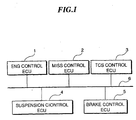
- Fig. 1 shows the whole arrangement of a control system for an automotive vehicle according to the embodiment comprising electronic control units (hereinafter referred to as the "ECU's") 1 to 5 connected with each other via a network bus 6.
- ECU's electronice control units
- An ENG control ECU 1 controls operation of an engine in response to operation of an accelerator pedal operated by a driver of the vehicle, etc.
- An MISS control ECU 2 controls an automatic transmission of the vehicle according to the operating conditions of the engine.
- a TCS control ECU 3 detects a slip of driving wheels and controls an output torque of the engine.
- a suspension control ECU 4 controls a suspension (active suspension) system of the vehicle depending on the operating conditions of the engine.
- a brake control ECU 5 detects a slip of wheels and controls braking operation.
- ECU's 1 to 5 are required to be permitted to mutually monitor control parameters and operating parameters detected by sensors, some of the sensors being collectively shown in Fig. 2, and hence are connected to each other by way of the network bus 6 for transmission of data necessitated by each other.
- Fig. 2 shows the arrangement of the ENG control ECU 1 which comprises a central processing unit (hereinafter referred to as "the CPU") 101, an input/output interface 104 connecting a plurality of sensors 11, and a plurality of actuators, such as fuel injection valves, to the CPU 101.
- the CPU 101 is connected via a bus line 107 to a RAM (Random Access Memory) 102, a ROM (Read Only Memory) 103, and a communication control IC (Integrated Circuit) 105.
- the communication control IC 105 is connected via a bus interface 106 to the network bus 6.
- the CPU 101 determines control parameters based on output signals from the sensors 11 according to a program stored in the ROM 103 for driving the actuators 12.
- the RAM 102 temporarily stores data of results of computation.
- the communication control IC controls transmission of a message to the network bus and reception of a message from the network bus.
- Fig. 3 shows details of the bus interface 106 connected to the communication control IC 105, and the network bus 6 comprised of twisted pair lines 6b and 6c connected at both ends of thereof to each other via respective terminal resistances 6a, 6a.
- the communication control IC 105 has a first sending terminal connected to a base of a transistor 119 via a resistance 115.
- the transistor 119 has an emitter thereof connected to a power supply line VSUP and a collector thereof connected via a resistance 116 to an inverting input terminal of a comparator 111 and to one 6b of the twisted pair lines 6b and 6c.
- the communication control IC 105 has a second sending terminal connected to a base of a transistor 120 via a resistance 117.
- the transistor 120 has an emitter thereof grounded and a collector thereof connected via a resistance 118 to a non-inverting input terminal of the comparator ill and to one 6c of the twisted pair lines 6b and 6c.
- the non-inverting input terminal of the comparator 111 is connected via a resistance 112 to the power supply line VSUP, and also via a resistance 113 to the inverting input terminal of the comparator ill.
- the comparator 111 has its inverting input terminal grounded via a resistance 114, and delivers an output signal therefrom to a receiving terminal of the communication control IC 105.
- the resistances 116 and 118 are each set to approximately 30 ⁇ , the resistances 112 and 114 to approximately 2 k ⁇ , the resistance 113 to approximately 200 ⁇ , and the terminal resistances 6a to approximately 100 ⁇ .
- the first and second sending terminals of the communication control IC 106 are supplied with pulse signals reverse to each other in phase.
- both the transistors 119 and 120 are turned on to set the voltage of the one twisted pair line 6b at the high level and the other twisted pair line 6c at the low level.
- both the transistors 119 and 120 are turned off to set the voltage of the one twisted pair line 6b at the low level and the other twisted pair line 6c at the high level.
- a signal is sent out to the network bus 6.
- the ECU's 2 to 5 are basically constructed in the same manner. Therefore, even if one of the ECU s sends out a signal which sets the voltage of the one twisted pair line 6b at the low level (i.e. sets the voltage of the other twisted pair line 6c at the high level) , when another Ecu sends out a signal which sets the voltage of the one twisted pair line 6b at the high level, the state of the voltage of the twisted pair line 6b is set to the high level. Therefore, in the present embodiment, a state in which the one twisted pair line line 6b is at the high level (the other twisted pair line 6c is at the low level) is defined as a dominant state, and an opposite state thereof as a recessive state.
- a token passing method is employed. This takes into consideration the fact that compared with a CSMA/CD (Carrier Sense Multiple Access with Collision Detection) method which is capable settling the collision, the token passing method is advantageous in respect of an electric delay on the network bus, and is capable of easily determining the maximum message delay time period, allowing the network system to be be designed easily.
- CSMA/CD Carrier Sense Multiple Access with Collision Detection
- Fig. 4a and Fig. 4b show formats of messages used in data transmission in the present embodiment.
- Fig. 4a shows a format of a data message (second message) for sending a token (representative of the transmission right) and data
- Fig. 4b shows that of a token message (first message) for sending the token alone.
- the ECU's constituting the network system will be referred to as the nodes 1 to 5.
- a field F1 notifies the start of a message, which is formed by one dominant bit. This field is used for synchronization of all the nodes constituting the network system.
- a field P2 designates an address of a destination node to which the token is to be transferred, which is formed by four bits of data.
- the node address is set e.g. to one of values 0 to 4 in a manner corresponding to the ECU's 1 to 5.
- a field F3 designates a kind of message (token message or data message).
- a field F4 is a data unit comprised of a DN (Destination Node) field designating a node or nodes which should receive data contained in a DATA field, a DLC (Data Length) filed designating the length of a byte of the DATA field, an ID (Identifier) filed forming an identifier of the data, and the DATA filed containing information to be transmitted.
- DN Disination Node
- DLC Data Length
- ID Identifier
- the length of the DATA field is variable as can be presumed from the above description, and the total length of the data unit is variable within the range of 32 to 96 bytes.
- a delimitter (dividing character) having one recessive bit is interposed between the field F5 and the field F6.
- a field F6 is a second response field into which a data-acknowledging response (second acknowledge character) should be written by a node having normally or safely received the data, which is formed by an acknowledge slot having two bits.
- a sending node sends a message having the acknowledge slot as recessive bits, and the node or nodes which is/are designated in the message as one or ones to receive the information and has/have normally or safely received the data make(s) the data-acknowledging response by overwriting two dominant bits therein.
- a delimitter having two recessive bits is interposed between the fields F6 and F7.
- a field F7 is a first response field into which a token-acknowledging response (first acknowledge character) should be written by a node having normally or safely received the token, which is formed by an acknowledge slot having two bits, similarly to the field F6.
- the sending node sends a message having the acknowledge slot as recessive bits, and the node having received the token makes the token-acknowledging response by overwriting two dominant bits therein.
- a delimitter formed by two recessive bits is interposed between the filed F7 and the field F8.
- a field F8 designates the end of the message, and is formed by six recessive bits.
- the field F7 and the field F6 are provided as fields into which acknowledgement of the token and acknowledgement of data are made, respectively, which makes it possible for a sending end to promptly confirm whether or not the transfer of the token and the transmission of data have been successfully carried out.
- the token message shown in Fig. 4b is constructed such that the fields F4 to F6 are deleted from the data message, and a delimitter is interposed between the fields F3 and F7.
- a node to which the token is to be transferred is a node designated in the field F2 (TA)
- the token address is normally set by adding a value of one to the address of the sending node itself, and a message continues to be sent out until a token-acknowledging response is detected, by sequentially increasing the token address by an incremental value of 1. However, when a calculated value of the token address reaches a value of 16, the token address is set to 0, thus circulating token address through values of of 0 to 15.
- the node corresponding to the token address set in the message When the node corresponding to the token address set in the message has received the token, it overwrites two dominant bits into the acknowledge slot of the field F7 (TACK), thereby making the token-acknowledging response. When the token-acknowledging response is thus overwritten and the message normally terminates in the field F8 (EOM), the sending node having sent the token completes the transfer of the token, and the receiving node has acquired the token.
- TACK acknowledge slot of the field F7
- EOM the message normally terminates in the field F8
- the transmission error is detected by monitoring of data, detection by CRC, detection of bit stuff error, and a message format check.
- a transmission error is detected when data a sending node is transmitting does not coincide with data loaded on the bus.
- this monitoring of data is inhibited with the acknowledge slots of the fields F6 and F7, and one recessive bit subsequent thereto.
- a transmission error is detected when an error is found as to CRC characters set in the field F5 (FCS), and this detection is performed by nodes other than the sending node.
- bit stuff error detection it is determined that there is an error in transmission when more than 5 consecutive bits designate the same logical state, and this detection is performed by nodes other than the sending node.
- the fields F6 (DACK), F7 (TACK), F8 (EOM) and the delimitters are executed from objects of monitoring.
- an error is detected when an illegal logical state is found in the fields of the fixed-logical-state bits (the fields F3, F8 and the delimitters), and this type of error detection is performed by nodes other than the sending node.
- a node having detected the error immediately sends out an error message (six consecutive dominant bits), whereby even if a transmission error is detected by a node or nodes other than the sending node, the sending node can recognize the transmission error.
- the communication control IC 105 of each of the ECU's 1 to 5 determines at a step S1 of Fig. 5 whether or not the network bus is idling, to determinate whether the data transmission system is in a state in which the token has not been generated immediately after the start of system, or has been lost due to failure of a node having received the token. If the answer to this question is negative (NO), i.e. if another ECU is sending a message, the present program is immediately terminated.
- NO negative
- the present ECU starts data transmission via the communication control IC 105 and the bus interface 106 at a step S2, assuming that the present node has acquired the token. Then, data sent from the present node is compared with data on the network bus 6 bit by bit to determine whether both the data are identical to each other at a step S3. If the answer to this question is affirmative (YES), i.e.
- the present program proceeds to a step S4, where it is determined whether or not transmission of the whole sequence of data has been completed. If the answer to this question is negative (NO), the program returns to the step S3, where data subsequently sent out is compared with data loaded on the network bus, in the same manner as described above.
- the present node is found to be defeated in contention for acquiring the token to stop data transmission when the above-described procedure is carried out.
- the above-mentioned method of the error detection by monitoring data is utilized for determining that the data sent out and the data loaded on the system bus do not coincide with each other.
- the coincidence of the data is determined by calculating an exclusive OR of the data sent out and the data received from the network bus 6.
- the data sent out from the present node is different from the data loaded on the network bus 6, it means that there has been a contention for the token with other nodes, and the present node has been defeated in the contention, so that the data transmission is stopped at a step S5, followed by terminating the present program.
- step S6 determines whether or not the transfer of the token has been completed, by making a check for the token-acknowledging response. If the transfer of the token has not been completed, a value of 1 is added to the token address of the token message, and then the resulting token message is sent out to the network bus 6 at a step S7. The steps S6 and S7 are repeatedly carried out until the transfer of the token is completed, whereupon the present program is terminated.
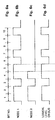
- bits corresponding to the bit numbers 1 to 4 shown in Fig. 6a are in the same logical states, respectively, and the logical states of the data sent from Node 1 and Node 2, and the logical state of the network bus are all equal to each other. Accordingly, Node 1 and Node 2 both continue to send out respective messages from bit No. 1 to bit No.4.
- Fig. 6a to Fig. 6d show a case where two nodes are in contention for the token.
- a contention for the token arises among more than two nodes.
- a token is generated or initially given to one of the nodes by contention for the token as described above, and then the token is circulated through or transferred round the nodes. This makes it possible to promptly generate the token by giving a chance of acquiring the token equally to all the nodes, enabling the system to function efficiently.
- the present invention is not limited to the above embodiment, but as a manner of mediation of contention, the logical state 0 may be used for a dominant bit and the logical state 1 for a recessive bit, inversely to the above embodiment.
- a node to which the token is first transferred is not necessarily restricted to a node having a node address following the address having initially acquired the token, but the token may be first transferred to a predetermined node having the smallest node address, then permitting the node to circulate through the nodes in a predetermined cycle.
- the first acknowledge character to be overwritten into the field F7 is referred to as the token ACK, while the second acknowledge character to be overwritten in the field F6 as the data ACK.
- the token data address is increased by an incremental value of 1 and then the resulting token message is sent out. This is for transferring the token alone to a node subsequent to the node to which the token has not been successfully transferred, since reception of the data written in the field F4 has been acknowledged.
- the token address is increased by an incremental value of 1 and the token message containing the resulting token address is transmitted, but the retransmission of data is not carried out.
- the circulation of the token is performed in preference to the transmission of data to permit smooth circulation of the token. Further, the data is transmitted again, if possible, when the token is acquired next time.
- Fig. 7 shows this variation of the procedure of transmission control performed by the communication control IC 105 for terminating the transmission upon completion of the sending of the message or upon detection of an error message.
- an error in transmission is detected by a sending node or a receiving node, whereupon an error message is sent out from the node having detected the error, thereby terminating the transmission.
- step S21 of Fig. 7 it is determined whether or not an error has occurred to transmission. If the answer to this question is negative (NO), it is determined at a step S22 whether or not the transfer of the token is completed (whether or not the token ACK is detected) . If the transfer of the token has been completed, first and second counters CT1, CT2, referred to hereinafter, are reset at a step S30, followed by terminating the present program. If the answer to the question of the step S22 is negative (NO) , i.e. if no error has occurred during the transmission, but the transfer of the token is not completed; the program proceeds to a step S23, where it is determined whether or not the data has been successfully transmitted (whether or not the data ACK is detected) . If it is determined that the data has been successfully transmitted, the transfer of the token is performed at a step S29, and then the first and second counters CT1, CT2 are reset at the step S30, followed by terminating the program.
- step S23 if the answer to the question of the step S23 is negative (NO), i.e. if no error has occurred during the transmission, but neither the transfer of the token nor the transmission of the data is successfully carried out (neither the token ACK nor the data ACK is detected), the program proceeds to a step S24, where an count value of the first counter CT1 is increased by an incremental value of 1, and it is determined at a step S25 whether or not the resulting count value of the first counter CT1 is equal to a first predetermined value C1 (which is set e.g. to a value of 2).
- step S21 It the answer to the question of the step S21 is affirmative (YES), i.e. if an error has occurred to transmission, a count value of the second counter CT2 is increased by an incremental value of 1 at a step S26, and it is determined at a step 527 whether or not the resulting count value of the second counter CT2 is equal to a second predetermined value C2 (which is set e.g. to a value of 5).
- C2 which is set e.g. to a value of 5
Description
- This invention relates to a method of transmitting data between a plurality of electronic control units installed on an automotive vehicle via a common communication line connecting these electronic control units.
- Conventionally, in performing mutual data transmission between a plurality of electronic control units (hereinafter referred to as the "ECU's" installed on an automotive vehicle via a common communication line (hereinafter referred to as "the network bus") connecting the ECU's, a token passing method is employed for circulating a transmission right round the ECU's in a predetermined sequence to permit an ECU having received the transmission right to send out data to the network bus.
- When a data transmission system employing the token passing method is started, the following methods are conventionally known for initially rendering (i.e. generating) the transmission right to one of the ECU's:
- (1) Fixed ECU method of initially rendering the transmission right to a particular ECU determined in advance in a fixed manner.
- (2) Waiting method in which all the ECU's start transmitting data assuming that they are each initially rendered with the transmission right, stop transmitting data when collision of data occurs, and restart data transmission after waiting for predetermined waiting time periods set to the ECU's, respectively, repeatedly carrying out this procedure until no collision occurs, to thereby restrict an initial holder of the transmission right to one of the ECU's.
-
- However, the fixed ECU method suffers from a problem that if the particular ECU to which the transmission right is to be initially rendered is in failure, the transmission right cannot be produced for ever.
- With the waiting method as well, there is an inconvenience that it takes much time to generate the transmission right, and time is wastefully consumed before the ECU's start to cooperate as a network.
- On the other hand, in the data transmission system using the token passing method, it is a known technique to add broadcast data to a message for transmission to transfer the transmission right to the next ECU, as disclosed e.g. in Japanese Patent Publication (Kokoku) No. 1-58900.
- However, according to this conventional technique, the message data format is not constructed such that a sending end can confirm safe and accurate transfer of each of the transmission right and data, and hence there is room for improvement thereof to expedite the transmission.
- Further, Japanese Patent Publication (Kokoku) No. 1-57856 (hereinafter referred to as the first prior art) discloses a technique that when data transmission is not successfully carried out, retransmission of data is performed upon the transmission right returning to the present ECU after having been transferred round the ECU's, taking into consideration the fact that if retransmission of the data is carried out immediately, there is a high possibility of failure thereof.
- Further, Japanese Provisional Patent Publication (Kokai) No. 62-159539 discloses a data transmission system (hereinafter referred to as "the second prior art") in which when transmission of the data is not successfully carried out, the data is retransmitted within a limit of a predetermined number of times, which number can be changed or set by another control system.
- According to the first prior art, the retransmission of data is performed only after the transmission right has been transferred round the ECU's once even if the immediate transmission of data might be successful (e.g. when failure of transmission was caused by a noise during transmission), which is an inconvenience to be eliminated for prompt completion of data transmission.
- Further, according to the second prior art, the retransmission of data is carried out immediately after failure thereof within the predetermined number of times set by the other control system. However, this number is not set by the sending end itself, and hence it is difficult to perform prompt reaction to failure of transmission.
- Further, in making a check as to whether connection between one member (ECU) and another (ECU) of the network is safely established, a special message is sent out from the one member for a response from the other, based on which it is determined whether the connection is safely established.
- When the special message is used, however, the. data transmission and transfer of the transmission right cannot be performed while the special message is being sent out, which results in degraded transmission efficiency. Further, when the other member (ECU) goes faulty or disconnected from the network, the state of the connection is not certain until the check therefor is carried out again, and hence there is a possibility of continuing to transfer the transmission right to the ECU disconnected.
- H. Eing. et al., «Das lokale SP-Netzwerk», Elektronik Vol. 32, No. 11, pages 73-78, discloses the structure of a typical data packet. At the end the data packet has an end acknowledgement for acknowledging the receipt for the whole data block. The end acknowledgement is only output if the whole data block is recognized as error-free.
- EP-A-0 216 372 discloses a data bus system for vehicles, wherein a plurality of different users are able to communicate via a common data bus. The system provides the following features: a) the users are each connected with the data bus via a control station, b) the control stations have registers for storing data required or delivered by the affiliated users, c) the stations are permanently connected to the data bus for receiving data required by the affiliated user, d) the stations are sequentially connected to the data bus for sequentially sending data delivered by the affiliated user, and e) the data handed over to the bus carry an identification sign.
- It is an object of the invention to provide a method of transmitting data, which permits prompt confirmations as to whether the transfer of the transmission right and the transmission of data are carried out successfully, respectively, thereby smoothly circulating the transmission right.
- To attain the object of the invention, there is provided a data transmission method for connecting a plurality of control systems installed on a vehicle by at least one common signal line, and transmitting a message between the plurality of control systems while circulating a transmission right through the plurality of control systems.
- The data transmission method according to the invention is characterized in that the message comprises a first response field for receiving a first acknowledging response output from a control system having received the transmission right, and a second response field for receiving a second acknowledging response output from a control system having received data.
- Preferably, a processing corresponding to the first acknowledging response is performed in preference to a processing corresponding to absence of the second acknowledging response.
- Preferably, the processing corresponding to the first acknowledging response is waiting for reception of the transmission right next time or continuation of transfer of the transmission right, and the processing corresponding to absence of the second acknowledging response is retransmission of the data.
- Preferably, the message is classified into a first message having a first response field for receiving a first acknowledging response output from a control system having received the transmission right, and a second message having a second response field for receiving a second acknowledging response output from a control system having received data; and
each of the plurality of control systems judges that transfer of the transmission right is completed irrespective of whether the second acknowledging response is detected or not, if the first acknowledging response is detected when the second message is sent out from the control system having received data, and does not perform transmission of the message until the transmission right is acquired next time, whereas the each of the plurality of control systems sends out the first message to continue the transfer of the transmission right when the first acknowledging response is not detected. - The above and other object, features, and advantages of the invention will become more apparent from the following detailed description taken in conjunction with the accompanying drawings.
-
- Fig. 1 is a block diagram showing the whole arrangement of a control system for an automotive vehicle according to an embodiment of the invention;
- Fig. 2 is a block diagram showing the arrangement of an electronic control unit appearing in Fig. 1;
- Fig. 3 is a circuit diagram showing details of a bus interface appearing in Fig. 2;
- Fig. 4a is a diagram showing a format of a message containing a data unit for transmission between electronic control units;
- Fig. 4b is a diagram showing a format of a message containing no data unit;
- Fig. 5 is a flowchart showing a program for initially generating a token (transmission right) when the token has not been generated or lost;
- Fig. 6a to Fig. 6d collectively form a timing chart which is useful in explaining a manner of mediation for settling contention for the transmission 20 right, in which:
- Fig. 6a shows bit Nos.;
- Fig. 6b shows data transmitted from a node 1;
- Fig. 6c shows data transmitted from a node 2;
- Fig. 6d shows logical levels on a bus; and
- Fig. 7 is a flowchart showing a program for terminating the data transmission.
-
- The invention will described in detail with reference to drawings showing an embodiment thereof.
- Fig. 1 shows the whole arrangement of a control system for an automotive vehicle according to the embodiment comprising electronic control units (hereinafter referred to as the "ECU's") 1 to 5 connected with each other via a network bus 6. An ENG control ECU 1 controls operation of an engine in response to operation of an accelerator pedal operated by a driver of the vehicle, etc. An MISS control ECU 2 controls an automatic transmission of the vehicle according to the operating conditions of the engine. A TCS control ECU 3 detects a slip of driving wheels and controls an output torque of the engine. A suspension control ECU 4 controls a suspension (active suspension) system of the vehicle depending on the operating conditions of the engine. A brake control ECU 5 detects a slip of wheels and controls braking operation. These ECU's 1 to 5 are required to be permitted to mutually monitor control parameters and operating parameters detected by sensors, some of the sensors being collectively shown in Fig. 2, and hence are connected to each other by way of the network bus 6 for transmission of data necessitated by each other.
- Fig. 2 shows the arrangement of the ENG control ECU 1 which comprises a central processing unit (hereinafter referred to as "the CPU") 101, an input/output interface 104 connecting a plurality of sensors 11, and a plurality of actuators, such as fuel injection valves, to the CPU 101. The CPU 101 is connected via a bus line 107 to a RAM (Random Access Memory) 102, a ROM (Read Only Memory) 103, and a communication control IC (Integrated Circuit) 105. The communication control IC 105 is connected via a bus interface 106 to the network bus 6.
- The CPU 101 determines control parameters based on output signals from the sensors 11 according to a program stored in the ROM 103 for driving the actuators 12.The RAM 102 temporarily stores data of results of computation. The communication control IC controls transmission of a message to the network bus and reception of a message from the network bus.
- Fig. 3 shows details of the bus interface 106 connected to the communication control IC 105, and the network bus 6 comprised of twisted pair lines 6b and 6c connected at both ends of thereof to each other via respective terminal resistances 6a, 6a.
- The communication control IC 105 has a first sending terminal connected to a base of a transistor 119 via a resistance 115. The transistor 119 has an emitter thereof connected to a power supply line VSUP and a collector thereof connected via a resistance 116 to an inverting input terminal of a comparator 111 and to one 6b of the twisted pair lines 6b and 6c.
- The communication control IC 105 has a second sending terminal connected to a base of a transistor 120 via a resistance 117. The transistor 120 has an emitter thereof grounded and a collector thereof connected via a resistance 118 to a non-inverting input terminal of the comparator ill and to one 6c of the twisted pair lines 6b and 6c.
- The non-inverting input terminal of the comparator 111 is connected via a resistance 112 to the power supply line VSUP, and also via a resistance 113 to the inverting input terminal of the comparator ill. The comparator 111 has its inverting input terminal grounded via a resistance 114, and delivers an output signal therefrom to a receiving terminal of the communication control IC 105.
- In the circuitry shown in Fig. 3, the resistances 116 and 118 are each set to approximately 30 Σ, the resistances 112 and 114 to approximately 2 kΣ, the resistance 113 to approximately 200 Σ, and the terminal resistances 6a to approximately 100 Σ.
- The first and second sending terminals of the communication control IC 106 are supplied with pulse signals reverse to each other in phase. When the first ending terminal is at a low level and the second sending terminal is at a high level, both the transistors 119 and 120 are turned on to set the voltage of the one twisted pair line 6b at the high level and the other twisted pair line 6c at the low level. When the first sending terminal is at the high level and the second sending terminal is at the low level, both the transistors 119 and 120 are turned off to set the voltage of the one twisted pair line 6b at the low level and the other twisted pair line 6c at the high level. Thus, a signal is sent out to the network bus 6.
- As the potential of the one twisted pair line 6b goes high and low, the output from the comparator 111 goes low and high, thereby receiving a signal loaded on the network bus 6.
- The ECU's 2 to 5 are basically constructed in the same manner. Therefore, even if one of the ECU s sends out a signal which sets the voltage of the one twisted pair line 6b at the low level (i.e. sets the voltage of the other twisted pair line 6c at the high level) , when another Ecu sends out a signal which sets the voltage of the one twisted pair line 6b at the high level, the state of the voltage of the twisted pair line 6b is set to the high level. Therefore, in the present embodiment, a state in which the one twisted pair line line 6b is at the high level (the other twisted pair line 6c is at the low level) is defined as a dominant state, and an opposite state thereof as a recessive state.
- Next, a method of data transmission between the ECU's will be described. In the present embodiment, a token passing method is employed. This takes into consideration the fact that compared with a CSMA/CD (Carrier Sense Multiple Access with Collision Detection) method which is capable settling the collision, the token passing method is advantageous in respect of an electric delay on the network bus, and is capable of easily determining the maximum message delay time period, allowing the network system to be be designed easily.
- Fig. 4a and Fig. 4b show formats of messages used in data transmission in the present embodiment. Fig. 4a shows a format of a data message (second message) for sending a token (representative of the transmission right) and data, while Fig. 4b shows that of a token message (first message) for sending the token alone. In the following description, the ECU's constituting the network system will be referred to as the nodes 1 to 5.
- In Fig. 4a, a field F1 (SOM) notifies the start of a message, which is formed by one dominant bit. This field is used for synchronization of all the nodes constituting the network system.
- A field P2 (TA) designates an address of a destination node to which the token is to be transferred, which is formed by four bits of data. The node address is set e.g. to one of values 0 to 4 in a manner corresponding to the ECU's 1 to 5.
- A field F3 (CTL) designates a kind of message (token message or data message).
- A field F4 (DATA UNIT) is a data unit comprised of a DN (Destination Node) field designating a node or nodes which should receive data contained in a DATA field, a DLC (Data Length) filed designating the length of a byte of the DATA field, an ID (Identifier) filed forming an identifier of the data, and the DATA filed containing information to be transmitted.
- In this connection, the length of the DATA field is variable as can be presumed from the above description, and the total length of the data unit is variable within the range of 32 to 96 bytes.
- A field F5 (FCS) is a CRC (Cyclic Redundancy Check) field comprised of a sequence (CRC character sequence) of characters for error detection having 16 bits obtained by using the following equation (1) as a generating polynomial:
- A delimitter (dividing character) having one recessive bit is interposed between the field F5 and the field F6.
- A field F6 (DACK) is a second response field into which a data-acknowledging response (second acknowledge character) should be written by a node having normally or safely received the data, which is formed by an acknowledge slot having two bits. A sending node sends a message having the acknowledge slot as recessive bits, and the node or nodes which is/are designated in the message as one or ones to receive the information and has/have normally or safely received the data make(s) the data-acknowledging response by overwriting two dominant bits therein. A delimitter having two recessive bits is interposed between the fields F6 and F7.
- A field F7 (TACK) is a first response field into which a token-acknowledging response (first acknowledge character) should be written by a node having normally or safely received the token, which is formed by an acknowledge slot having two bits, similarly to the field F6. The sending node sends a message having the acknowledge slot as recessive bits, and the node having received the token makes the token-acknowledging response by overwriting two dominant bits therein. A delimitter formed by two recessive bits is interposed between the filed F7 and the field F8.
- A field F8 (EOM) designates the end of the message, and is formed by six recessive bits.
- In the present embodiment, the field F7 and the field F6 are provided as fields into which acknowledgement of the token and acknowledgement of data are made, respectively, which makes it possible for a sending end to promptly confirm whether or not the transfer of the token and the transmission of data have been successfully carried out.
- The token message shown in Fig. 4b is constructed such that the fields F4 to F6 are deleted from the data message, and a delimitter is interposed between the fields F3 and F7.
- Next, a method of circulating the token (transferring the token round the ECU's) will be described.
- If a node having received the token has data or information to be transmitted, it has to transfer the token together with the data. If the node has no data or information to be transmitted, it has to transmit the token alone. A node to which the token is to be transferred is a node designated in the field F2 (TA) The token address is normally set by adding a value of one to the address of the sending node itself, and a message continues to be sent out until a token-acknowledging response is detected, by sequentially increasing the token address by an incremental value of 1. However, when a calculated value of the token address reaches a value of 16, the token address is set to 0, thus circulating token address through values of of 0 to 15.
- When the node corresponding to the token address set in the message has received the token, it overwrites two dominant bits into the acknowledge slot of the field F7 (TACK), thereby making the token-acknowledging response. When the token-acknowledging response is thus overwritten and the message normally terminates in the field F8 (EOM), the sending node having sent the token completes the transfer of the token, and the receiving node has acquired the token.
- Next, a manner of detecting failure in transmission of a message will be described.
- When roughly classified, there are two types of failure in transmission: one in which there has been no transmission error but no data-acknowledging response is overwritten in the field F6 (DACK) of the acknowledge slot, and the other in which a transmission error has been detected during transmission of a message. When no data-acknowledging response has been made, this type of failure of transmission is detected by the sending node itself.
- On the other hand, the transmission error is detected by monitoring of data, detection by CRC, detection of bit stuff error, and a message format check.
- According to the error detection by monitoring of data, a transmission error is detected when data a sending node is transmitting does not coincide with data loaded on the bus. However, this monitoring of data is inhibited with the acknowledge slots of the fields F6 and F7, and one recessive bit subsequent thereto.
- According to the error detection by CRC, a transmission error is detected when an error is found as to CRC characters set in the field F5 (FCS), and this detection is performed by nodes other than the sending node.
- According to the bit stuff error detection, it is determined that there is an error in transmission when more than 5 consecutive bits designate the same logical state, and this detection is performed by nodes other than the sending node. However, the fields F6 (DACK), F7 (TACK), F8 (EOM) and the delimitters are executed from objects of monitoring.
- According to the error detection by the message format check, an error is detected when an illegal logical state is found in the fields of the fixed-logical-state bits (the fields F3, F8 and the delimitters), and this type of error detection is performed by nodes other than the sending node.
- When any of the above-described errors occurring during transmission is detected, a node having detected the error immediately sends out an error message (six consecutive dominant bits), whereby even if a transmission error is detected by a node or nodes other than the sending node, the sending node can recognize the transmission error.
- Next, a procedure of generating the token or initially rendering the token to one of the nodes when the token has not been generated or lost from the data transmission system will be described with reference to Fig. 5 and Fig. 6.
- The communication control IC 105 of each of the ECU's 1 to 5 determines at a step S1 of Fig. 5 whether or not the network bus is idling, to determinate whether the data transmission system is in a state in which the token has not been generated immediately after the start of system, or has been lost due to failure of a node having received the token. If the answer to this question is negative (NO), i.e. if another ECU is sending a message, the present program is immediately terminated.
- On the other hand, if the network bus 6 is idle, i.e.no other ECU's are sending any message, the present ECU starts data transmission via the communication control IC 105 and the bus interface 106 at a step S2, assuming that the present node has acquired the token. Then, data sent from the present node is compared with data on the network bus 6 bit by bit to determine whether both the data are identical to each other at a step S3. If the answer to this question is affirmative (YES), i.e. the data sent out and the data on the network bus coincide with each other, it means that there is no contention between the data sent out from the present node and data from other nodes, or the present node remains undefeated in contention for acquiring the token, and hence data transmission is continued assuming that the present node has not lost the token yet. That is, the present program proceeds to a step S4, where it is determined whether or not transmission of the whole sequence of data has been completed. If the answer to this question is negative (NO), the program returns to the step S3, where data subsequently sent out is compared with data loaded on the network bus, in the same manner as described above.
- It goes without saying that there is a case in which the present node is found to be defeated in contention for acquiring the token to stop data transmission when the above-described procedure is carried out. Further, as a method of determining whether the data sent from the present node and the data loaded on the system bus coincide with each other, the above-mentioned method of the error detection by monitoring data is utilized for determining that the data sent out and the data loaded on the system bus do not coincide with each other. In the present case, more specifically, the coincidence of the data is determined by calculating an exclusive OR of the data sent out and the data received from the network bus 6.
- On the other hand, if the data sent out from the present node is different from the data loaded on the network bus 6, it means that there has been a contention for the token with other nodes, and the present node has been defeated in the contention, so that the data transmission is stopped at a step S5, followed by terminating the present program.
- If it is determined at the step S4 that the whole sequence of data has been sent out, i.e. if it is determined that the present node remains undefeated throughout the contention for acquiring the token, it is determined at a step S6 whether or not the transfer of the token has been completed, by making a check for the token-acknowledging response. If the transfer of the token has not been completed, a value of 1 is added to the token address of the token message, and then the resulting token message is sent out to the network bus 6 at a step S7. The steps S6 and S7 are repeatedly carried out until the transfer of the token is completed, whereupon the present program is terminated.
- Further, in determining a winner of contention, data formed by an identical sequence of bits is actually sent out a plurality of times for prevention of an erroneous determination due to noise or the like. Next, details of a manner of determining a winner of the contention will be described with reference to Fig. 6a to Fig. 6d.
- Let it be assumed that data are transmitted from Node 1 and Node 2 as shown in Fig. 6b and Fig. 6c, respectively. As described hereinbefore, a bit in the logical state "1" is a dominant bit, and a bit in the logical state "0 is a recessive bit. If contention occurs between the dominant bit and the recessive bit, the logical state on the network bus becomes equal to "1".
- In the case of data shown in Fig. 6b and Fig. 6c, bits corresponding to the bit numbers 1 to 4 shown in Fig. 6a are in the same logical states, respectively, and the logical states of the data sent from Node 1 and Node 2, and the logical state of the network bus are all equal to each other. Accordingly, Node 1 and Node 2 both continue to send out respective messages from bit No. 1 to bit No.4.
- However, at bit No. 5, the logical state of data sent from Node 1 is equal to '1', whereas the logical state of data sent from Node 2 is equal to "0". Accordingly, the logical state of the network bus becomes equal to the logical state "1" of the dominant bit sent from Node 1. Therefore, Node 1 having sent the dominant bit determines that it has not lost the token and continues to send the message, whereas Node 2 having the sent the recessive bit determines that it has lost the token and ceases to send the message.
- In this connection, Fig. 6a to Fig. 6d show a case where two nodes are in contention for the token. However, actually, there can occur a case in which a contention for the token arises among more than two nodes. However, it is impossible for all the nodes to continue sending the same sequence of data, and eventually, one node is necessarily determined to remain undefeated in the contention, without any inconveniences.
- As can be clearly understood from the above description, according to the present invention, when the control system is started or a node having received the token is in failure, a token is generated or initially given to one of the nodes by contention for the token as described above, and then the token is circulated through or transferred round the nodes. This makes it possible to promptly generate the token by giving a chance of acquiring the token equally to all the nodes, enabling the system to function efficiently.
- Further, the present invention is not limited to the above embodiment, but as a manner of mediation of contention, the logical state 0 may be used for a dominant bit and the logical state 1 for a recessive bit, inversely to the above embodiment. Further, after the token has been generated through contention, a node to which the token is first transferred is not necessarily restricted to a node having a node address following the address having initially acquired the token, but the token may be first transferred to a predetermined node having the smallest node address, then permitting the node to circulate through the nodes in a predetermined cycle.
- Next, a procedure of processing performed when no data-acknowledging response has been received after a sending node has sent a data message. In the following description, the first acknowledge character to be overwritten into the field F7 is referred to as the token ACK, while the second acknowledge character to be overwritten in the field F6 as the data ACK.
- The token data address is increased by an incremental value of 1 and then the resulting token message is sent out. This is for transferring the token alone to a node subsequent to the node to which the token has not been successfully transferred, since reception of the data written in the field F4 has been acknowledged.
- Since the transfer of the token is completed, retransmission of data is not carried out. The data is retransmitted, if possible, when the token is acquired next time.
- The token address is increased by an incremental value of 1 and the token message containing the resulting token address is transmitted, but the retransmission of data is not carried out. Thus, the circulation of the token is performed in preference to the transmission of data to permit smooth circulation of the token. Further, the data is transmitted again, if possible, when the token is acquired next time.
- As described above, even if the data ACK is not detected, it is judged, so long as the token ACK is detected, that the transfer of the token is completed, and the retransmission of data is inhibited. Further, when neither the data ACK nor the token ACK is detected, only the transfer of the token is tried again without retransmitting the data, whereby it is possible to circulate the token smoothly. The preference is given to the transfer of the token since the retransmission of data performed immediately after detection of a transmission error requires the maximum delay time of the system to be set to a longer time period than when the transfer of the token is preferentially performed as in the present embodiment.
- Although in the above example, when neither the token ACK nor the data ACK is detected, the token message is permitted to be sent out immediately, and at the same time retransmission of data is inhibited, this is not limitative, but the transfer of the token may be performed after retransmission of data is tried one or two times.
- Fig. 7 shows this variation of the procedure of transmission control performed by the communication control IC 105 for terminating the transmission upon completion of the sending of the message or upon detection of an error message.
- In the following description, it should be understood that an error in transmission is detected by a sending node or a receiving node, whereupon an error message is sent out from the node having detected the error, thereby terminating the transmission.
- At a step S21 of Fig. 7, it is determined whether or not an error has occurred to transmission. If the answer to this question is negative (NO), it is determined at a step S22 whether or not the transfer of the token is completed (whether or not the token ACK is detected) . If the transfer of the token has been completed, first and second counters CT1, CT2, referred to hereinafter, are reset at a step S30, followed by terminating the present program. If the answer to the question of the step S22 is negative (NO) , i.e. if no error has occurred during the transmission, but the transfer of the token is not completed; the program proceeds to a step S23, where it is determined whether or not the data has been successfully transmitted (whether or not the data ACK is detected) . If it is determined that the data has been successfully transmitted, the transfer of the token is performed at a step S29, and then the first and second counters CT1, CT2 are reset at the step S30, followed by terminating the program.
- On the other hand, if the answer to the question of the step S23 is negative (NO), i.e. if no error has occurred during the transmission, but neither the transfer of the token nor the transmission of the data is successfully carried out (neither the token ACK nor the data ACK is detected), the program proceeds to a step S24, where an count value of the first counter CT1 is increased by an incremental value of 1, and it is determined at a step S25 whether or not the resulting count value of the first counter CT1 is equal to a first predetermined value C1 (which is set e.g. to a value of 2). When this step is first carried out, CT1 < C1 holds, so that retransmission of the message which has not been successfully transmitted is performed at a step S28, followed by terminating the program. If the acknowledging responses (the token ACK and the data ACK) continue not to be detected thereafter until CT1 = C1 holds at the step 525, the program proceeds therefrom to the step S29, where the token is transferred by the token message, and the counters CT1, CT2 are reset, at the step S30, followed by terminating the program.
- It the answer to the question of the step S21 is affirmative (YES), i.e. if an error has occurred to transmission, a count value of the second counter CT2 is increased by an incremental value of 1 at a step S26, and it is determined at a step 527 whether or not the resulting count value of the second counter CT2 is equal to a second predetermined value C2 (which is set e.g. to a value of 5). When this step is first carried out, CT2 < C2 holds, so that the retransmission of the message which has not been successfully transmitted is performed at the step S28, followed by terminating the program. If the transmission error continues to occur until CT2 = C2 holds at the step S27, the program proceeds therefrom to the steps S29 and S30, followed.
Claims (4)
- A data transmission method for connecting a plurality of control systems (1, 2, 3, 4, 5) installed on a vehicle by at least one common signal line(6), and transmitting a message between said plurality of control systems (1, 2, 3, 4, 5) while circulating a transmission right through said plurality of control systems (1, 2, 3, 4, 5),
characterized in that said message comprises a first response field (F7(TACK)) for receiving a first acknowledging response output from a control system having received said transmission right, and a second response field (F6(DACK)) for receiving a second acknowledging response output from a control system having received data. - A data transmission method according to claim 1, wherein a processing corresponding to said first acknowledging response is performed in preference to a processing corresponding to absence of said second acknowledging response.
- A data transmission method according to claim 2, wherein said processing corresponding to said first acknowledging response is waiting for reception of said transmission right next time or continuation of transfer of said transmission right, and said processing corresponding to absence of said second acknowledging response is retransmission of said data.
- A data transmission method according to claim 1, wherein said message is classified into a first message having said first response field (F7 (TACK)) and a second message having said second response field (F6 (DACK)), and wherein each of said plurality of control systems (1, 2, 3, 4, 5) judges that transfer of said transmission right is completed irrespective of whether said second acknowledging response is detected or not, if said first acknowledging response is detected when said second message is sent out from said control system having received data, and does not perform transmission of said message until said transmission right is acquired next time, whereas said each of said plurality of control systems (1, 2, 3, 4, 5) sends out said first message to continue said transfer of said transmission right when said first acknowledging response is not detected.
Applications Claiming Priority (9)
| Application Number | Priority Date | Filing Date | Title |
|---|---|---|---|
| JP5048560A JP2947437B2 (en) | 1993-02-15 | 1993-02-15 | Data transmission method |
| JP4855993 | 1993-02-15 | ||
| JP5048559A JP2857655B2 (en) | 1993-02-15 | 1993-02-15 | Vehicle data transmission system |
| JP4856093 | 1993-02-15 | ||
| JP8021693 | 1993-03-15 | ||
| JP5080216A JP2784709B2 (en) | 1993-03-15 | 1993-03-15 | Vehicle data transmission system |
| JP5084079A JP2947496B2 (en) | 1993-03-18 | 1993-03-18 | Vehicle data transmission system |
| JP8407993 | 1993-03-18 | ||
| EP94102290A EP0612169B1 (en) | 1993-02-15 | 1994-02-15 | Data transmission method and system therefor |
Related Parent Applications (1)
| Application Number | Title | Priority Date | Filing Date |
|---|---|---|---|
| EP94102290A Division EP0612169B1 (en) | 1993-02-15 | 1994-02-15 | Data transmission method and system therefor |
Publications (2)
| Publication Number | Publication Date |
|---|---|
| EP1022877A1 EP1022877A1 (en) | 2000-07-26 |
| EP1022877B1 true EP1022877B1 (en) | 2004-06-23 |
Family
ID=27462227
Family Applications (4)
| Application Number | Title | Priority Date | Filing Date |
|---|---|---|---|
| EP00105838A Expired - Lifetime EP1022877B1 (en) | 1993-02-15 | 1994-02-15 | Data transmission method |
| EP00105840A Expired - Lifetime EP1022879B1 (en) | 1993-02-15 | 1994-02-15 | Data transmission system |
| EP00105839A Expired - Lifetime EP1022878B1 (en) | 1993-02-15 | 1994-02-15 | Data transmission system |
| EP94102290A Expired - Lifetime EP0612169B1 (en) | 1993-02-15 | 1994-02-15 | Data transmission method and system therefor |
Family Applications After (3)
| Application Number | Title | Priority Date | Filing Date |
|---|---|---|---|
| EP00105840A Expired - Lifetime EP1022879B1 (en) | 1993-02-15 | 1994-02-15 | Data transmission system |
| EP00105839A Expired - Lifetime EP1022878B1 (en) | 1993-02-15 | 1994-02-15 | Data transmission system |
| EP94102290A Expired - Lifetime EP0612169B1 (en) | 1993-02-15 | 1994-02-15 | Data transmission method and system therefor |
Country Status (4)
| Country | Link |
|---|---|
| US (4) | US5696904A (en) |
| EP (4) | EP1022877B1 (en) |
| CA (1) | CA2115730C (en) |
| DE (4) | DE69433866T2 (en) |
Families Citing this family (55)
| Publication number | Priority date | Publication date | Assignee | Title |
|---|---|---|---|---|
| DE69433866T2 (en) * | 1993-02-15 | 2005-06-30 | Honda Giken Kogyo K.K. | Method for transmitting data |
| JP2765538B2 (en) * | 1995-11-30 | 1998-06-18 | 日本電気株式会社 | Data transfer control device |
| GB9603582D0 (en) | 1996-02-20 | 1996-04-17 | Hewlett Packard Co | Method of accessing service resource items that are for use in a telecommunications system |
| GB9605048D0 (en) * | 1996-03-09 | 1996-05-08 | Jaguar Cars | Multiplexed electronic control systems |
| US5822543A (en) * | 1996-07-08 | 1998-10-13 | International Business Machines Corporation | Gathering data handling statistics in non-synchronous data communication networks |
| JP3117000B2 (en) * | 1997-02-21 | 2000-12-11 | 株式会社デンソー | Communication system and electronic control device used therein |
| US5931915A (en) * | 1997-05-13 | 1999-08-03 | International Business Machines Corporation | Method for processing early arrival messages within a multinode asynchronous data communications system |
| US6038689A (en) * | 1997-08-21 | 2000-03-14 | Digital Equipment Corporation | Fault notification system and process using local area network |
| ES2147119B1 (en) * | 1998-03-10 | 2001-03-16 | Mecanismos Aux Es Ind S L | SYSTEM TO TRANSFER BINARY INFORMATION. |
| DE19843810A1 (en) * | 1998-09-24 | 2000-03-30 | Philips Corp Intellectual Pty | Data bus |
| JP2000156685A (en) | 1998-11-18 | 2000-06-06 | Fuji Heavy Ind Ltd | Monitoring device for abnormality of vehicle control system |
| US6389550B1 (en) * | 1998-12-23 | 2002-05-14 | Ncr Corporation | High availability protocol computing and method |
| US6604038B1 (en) * | 1999-11-09 | 2003-08-05 | Power Talk, Inc. | Apparatus, method, and computer program product for establishing a remote data link with a vehicle with minimal data transmission delay |
| MXPA02004971A (en) * | 1999-11-17 | 2002-09-18 | Vehicle Enhancement Sys Inc | Method for data communication between a vehicle and a remote terminal. |
| US6661998B1 (en) * | 1999-12-23 | 2003-12-09 | Denso Corporation | Mobile station to base station communication and signal acknowledgement |
| US6484082B1 (en) * | 2000-05-24 | 2002-11-19 | General Motors Corporation | In-vehicle network management using virtual networks |
| DE10027017A1 (en) * | 2000-05-31 | 2002-02-28 | Bayerische Motoren Werke Ag | Operating method for a data bus for several participants |
| US6775690B1 (en) * | 2000-07-21 | 2004-08-10 | At&T Corp. | Time-dependent messaging |
| EP1202146A1 (en) * | 2000-10-23 | 2002-05-02 | Lucent Technologies Inc. | System for controlling electrical parameters of circuit components |
| IES20010064A2 (en) * | 2001-01-29 | 2002-04-17 | Eland Technologies Inc | Computer network system |
| US7164654B2 (en) * | 2001-03-09 | 2007-01-16 | Denso Corporation | ARQ parameter retransmission control for variable data rate channels |
| US6973492B2 (en) * | 2001-09-07 | 2005-12-06 | International Business Machines Corporation | Method and apparatus for collecting page load abandons in click stream data |
| EP1478943B1 (en) * | 2002-02-22 | 2008-02-20 | Robert Bosch Gmbh | Method and device for transmitting measurement data via a can bus in an object detection system for motor vehicles |
| JP4100108B2 (en) * | 2002-09-12 | 2008-06-11 | 株式会社デンソー | Control system |
| WO2004084505A1 (en) * | 2003-03-18 | 2004-09-30 | Fujitsu Limited | Transmission band assigning device |
| FR2852765B1 (en) * | 2003-03-21 | 2005-06-24 | Peugeot Citroen Automobiles Sa | SYSTEM FOR SECURING THE TRANSMISSION OF AT LEAST CERTAIN CONTROL FRAMES ON A MULTIPLEX INFORMATION TRANSMISSION NETWORK |
| US7461319B2 (en) * | 2003-04-04 | 2008-12-02 | Sun Microsystems, Inc. | System and method for downloading files over a network with real time verification |
| US7516244B2 (en) * | 2003-07-02 | 2009-04-07 | Caterpillar Inc. | Systems and methods for providing server operations in a work machine |
| US7532640B2 (en) | 2003-07-02 | 2009-05-12 | Caterpillar Inc. | Systems and methods for performing protocol conversions in a machine |
| US7983820B2 (en) | 2003-07-02 | 2011-07-19 | Caterpillar Inc. | Systems and methods for providing proxy control functions in a work machine |
| US7162339B2 (en) * | 2004-08-31 | 2007-01-09 | General Motors Corporation | automated vehicle calibration and testing system via telematics |
| DE102004050424B4 (en) * | 2004-10-15 | 2010-04-15 | Bosch Rexroth Ag | Method for transmitting data in a communication system |
| ATE436133T1 (en) * | 2004-11-29 | 2009-07-15 | Scania Cv Abp | METHOD FOR START-UP CONTROL OF NETWORK COMMUNICATIONS IN A COMMUNICATIONS NETWORK |
| JP4437468B2 (en) | 2004-12-06 | 2010-03-24 | 富士通テン株式会社 | Electronic control device for vehicle |
| JP2006309547A (en) * | 2005-04-28 | 2006-11-09 | Toshiba Corp | Information processor and information processing method |
| GB2431769B (en) * | 2005-10-25 | 2009-06-10 | Laurence Wrenn | Switching unit |
| EP1943781A1 (en) | 2005-11-03 | 2008-07-16 | Continental Teves AG & Co. oHG | Mixed signal switching circuit for an electronic protected control or regulation system |
| JP4681504B2 (en) * | 2006-05-22 | 2011-05-11 | ヤマハ発動機株式会社 | Electronic controller for remote control and remote operation system using the same |
| US20080082708A1 (en) * | 2006-09-29 | 2008-04-03 | Kar Leong Wong | Token hold off for chipset communication |
| KR101114609B1 (en) * | 2007-10-03 | 2012-03-05 | 후지쯔 가부시끼가이샤 | Radio communication device, radio communication control device, radio communication method, radio communication program storage medium, radio communication control method, and radio communication control program storage medium |
| FR2926943B1 (en) * | 2008-01-30 | 2012-01-13 | Canon Kk | METHODS OF TRANSMITTING AND RECONSTRUCTING DATA UNIT SEQUENCES, COMPUTER PROGRAM PRODUCT, STORAGE MEANS, TRANSMITTER NODES AND RECEIVER THEREFOR |
| DE102008012730B3 (en) * | 2008-03-05 | 2009-08-27 | Robert Bosch Gmbh | Electronic control and diagnostic device for operating a valve unit |
| US8238538B2 (en) | 2009-05-28 | 2012-08-07 | Comcast Cable Communications, Llc | Stateful home phone service |
| EP2355393B1 (en) * | 2010-01-21 | 2013-12-11 | Rohde & Schwarz GmbH & Co. KG | Method and apparatus for determining an optimized number of transmissions for a data packet in a multicast transmission system |
| US9172398B2 (en) * | 2010-07-08 | 2015-10-27 | Mitsubishi Electric Corporation | Vehicle data abnormality determination device |
| JP5651442B2 (en) * | 2010-11-29 | 2015-01-14 | 矢崎総業株式会社 | Operation support device, electronic apparatus, electronic control device, and control system |
| DE102011116642A1 (en) * | 2011-10-20 | 2013-04-25 | Audi Ag | Transmission device and method for the secure transmission of a sensor signal to a transmission destination and motor vehicle |
| EP2839608B1 (en) | 2012-03-21 | 2019-07-31 | Husqvarna AB | Hand held power tool, system and method |
| US10369942B2 (en) | 2014-01-06 | 2019-08-06 | Argus Cyber Security Ltd. | Hosted watchman |
| WO2016201091A1 (en) * | 2015-06-10 | 2016-12-15 | RunSafe Security, Inc. | System and method for guarding a controller area network |
| US10423475B2 (en) * | 2016-09-30 | 2019-09-24 | Microsoft Technology Licensing, Llc | Stateful tokens for communicating with external services |
| CN106628070B (en) * | 2016-11-09 | 2018-06-26 | 重庆长安工业(集团)有限责任公司 | Control method based on D30mm systems operation bench peculiar to vessel |
| EP3506584B1 (en) * | 2017-12-28 | 2020-12-23 | Vestel Elektronik Sanayi ve Ticaret A.S. | Method and apparatus for communication between a plurality of control boards |
| CN110213018B (en) * | 2019-05-09 | 2022-07-15 | 北京汽车股份有限公司 | Data communication method and device of vehicle-mounted bus and vehicle |
| CN114531314B (en) * | 2022-01-11 | 2023-12-22 | 宁波天擎航天科技有限公司 | Method for reliably transmitting big data in aerospace field, electronic equipment and storage medium |
Family Cites Families (23)
| Publication number | Priority date | Publication date | Assignee | Title |
|---|---|---|---|---|
| US4560985B1 (en) * | 1982-05-07 | 1994-04-12 | Digital Equipment Corp | Dual-count, round-robin ditributed arbitration technique for serial buses |
| US4590468A (en) * | 1983-03-10 | 1986-05-20 | Western Digital Corporation | Token access controller protocol and architecture |
| JPS59211143A (en) * | 1983-05-17 | 1984-11-29 | Nissan Motor Co Ltd | Car control circuit using microcomputer |
| US4556974A (en) * | 1983-10-07 | 1985-12-03 | Honeywell Inc. | Method for passing a token in a local-area network |
| US4551721A (en) * | 1983-10-07 | 1985-11-05 | Honeywell Inc. | Method for initializing a token-passing local-area network |
| US4725834A (en) * | 1984-02-27 | 1988-02-16 | American Telephone And Telegraph Company, At&T Bell Laboratories | Reliable broadcast protocol for a token passing bus network |
| US4715031A (en) * | 1985-09-23 | 1987-12-22 | Ford Motor Company | Vehicular data transfer communication system |
| DE3534216A1 (en) * | 1985-09-25 | 1987-04-02 | Bayerische Motoren Werke Ag | DATA BUS SYSTEM FOR VEHICLES |
| JPS62151903A (en) * | 1985-12-25 | 1987-07-06 | Nippon Denso Co Ltd | Electronic controller mounted on vehicle |
| JPS62159539A (en) * | 1986-01-07 | 1987-07-15 | Nec Corp | Data transmission equipment |
| US4860006A (en) * | 1986-06-05 | 1989-08-22 | Michael Barall | Heartbeat collision avoidance method and circuit |
| US4766530A (en) * | 1986-11-24 | 1988-08-23 | Westinghouse Electric Corp. | Token passing scheme for a predetermined configuration local area network |
| JPS6457856A (en) * | 1987-02-23 | 1989-03-06 | Nitsuko Ltd | Automatic incoming circuit in telephone set |
| JPH0771088B2 (en) * | 1987-04-06 | 1995-07-31 | 古河電気工業株式会社 | Multiplex transmission system |
| JPS6458756A (en) * | 1987-08-27 | 1989-03-06 | Inax Corp | Method of executing tile |
| JPS6458900A (en) * | 1987-08-28 | 1989-03-06 | Shimizu Construction Co Ltd | Piping reclamation shutoff valve |
| JPH06101732B2 (en) * | 1987-11-30 | 1994-12-12 | 三菱電機株式会社 | Communication control method |
| US4899143A (en) * | 1988-04-21 | 1990-02-06 | Bell Communications Research, Inc. | High capacity communication system over collision-type channels |
| JPH0769376B2 (en) * | 1989-08-30 | 1995-07-31 | マツダ株式会社 | Multiplex device for vehicle |
| JP2770282B2 (en) * | 1992-04-13 | 1998-06-25 | 本田技研工業株式会社 | Vehicle data transmission system |
| EP0580938B1 (en) * | 1992-06-26 | 2001-09-26 | Yokogawa Electric Corporation | Duplex communication control device |
| US5351241A (en) * | 1992-12-24 | 1994-09-27 | Intel Corporation | Twisted pair ethernet hub for a star local area network |
| DE69433866T2 (en) * | 1993-02-15 | 2005-06-30 | Honda Giken Kogyo K.K. | Method for transmitting data |
-
1994
- 1994-02-15 DE DE69433866T patent/DE69433866T2/en not_active Expired - Fee Related
- 1994-02-15 CA CA002115730A patent/CA2115730C/en not_active Expired - Fee Related
- 1994-02-15 DE DE69428930T patent/DE69428930T2/en not_active Expired - Fee Related
- 1994-02-15 DE DE69433882T patent/DE69433882T2/en not_active Expired - Fee Related
- 1994-02-15 EP EP00105838A patent/EP1022877B1/en not_active Expired - Lifetime
- 1994-02-15 DE DE69433098T patent/DE69433098T2/en not_active Expired - Fee Related
- 1994-02-15 EP EP00105840A patent/EP1022879B1/en not_active Expired - Lifetime
- 1994-02-15 EP EP00105839A patent/EP1022878B1/en not_active Expired - Lifetime
- 1994-02-15 EP EP94102290A patent/EP0612169B1/en not_active Expired - Lifetime
-
1995
- 1995-05-31 US US08/454,752 patent/US5696904A/en not_active Expired - Fee Related
- 1995-05-31 US US08/455,247 patent/US5586118A/en not_active Expired - Fee Related
- 1995-05-31 US US08/455,512 patent/US5764919A/en not_active Expired - Fee Related
- 1995-09-14 US US08/527,953 patent/US5659702A/en not_active Expired - Fee Related
Also Published As
| Publication number | Publication date |
|---|---|
| US5764919A (en) | 1998-06-09 |
| US5659702A (en) | 1997-08-19 |
| DE69428930T2 (en) | 2002-06-27 |
| DE69433098T2 (en) | 2004-03-25 |
| DE69433866D1 (en) | 2004-07-29 |
| EP1022877A1 (en) | 2000-07-26 |
| DE69433882D1 (en) | 2004-08-05 |
| EP0612169A3 (en) | 1995-10-11 |
| EP1022878B1 (en) | 2004-06-30 |
| DE69433098D1 (en) | 2003-10-02 |
| US5586118A (en) | 1996-12-17 |
| DE69433882T2 (en) | 2005-08-25 |
| DE69433866T2 (en) | 2005-06-30 |
| EP0612169A2 (en) | 1994-08-24 |
| EP1022879B1 (en) | 2003-08-27 |
| CA2115730C (en) | 1999-05-04 |
| EP1022879A1 (en) | 2000-07-26 |
| CA2115730A1 (en) | 1994-08-16 |
| EP1022878A1 (en) | 2000-07-26 |
| EP0612169B1 (en) | 2001-11-07 |
| DE69428930D1 (en) | 2001-12-13 |
| US5696904A (en) | 1997-12-09 |
Similar Documents
| Publication | Publication Date | Title |
|---|---|---|
| EP1022877B1 (en) | Data transmission method | |
| US5357525A (en) | Multiplex transmission system | |
| US5499247A (en) | Multiplex transmission system having plurality of nodes and common transmission line and using divided data areas | |
| US5293571A (en) | Receipt acknowledgement method in multiplex transmission | |
| JP2770282B2 (en) | Vehicle data transmission system | |
| JP2995348B2 (en) | Multiplex transmission method | |
| CA2226421C (en) | Data transmission method and system therefor | |
| CA2363980C (en) | Data transmission method and system therefor | |
| JP2781397B2 (en) | Multiplex transmission equipment | |
| JP2857655B2 (en) | Vehicle data transmission system | |
| JP2775659B2 (en) | Data transmission method | |
| JP2784709B2 (en) | Vehicle data transmission system | |
| JP2947437B2 (en) | Data transmission method | |
| JPH0722431B2 (en) | Multiplex communication system | |
| JP2947496B2 (en) | Vehicle data transmission system | |
| JP3175202B2 (en) | Method of storing received data in communication control circuit | |
| JP2544860B2 (en) | Signal transmission method | |
| EP0615366A1 (en) | Method and system for accessing a communication medium for asynchronous transmission | |
| JPH10136465A (en) | Vehicle data transmission system | |
| JPH05191415A (en) | Multiplex communication system | |
| JPH11112536A (en) | Vehicle multiplex communication equipment | |
| JPH10187598A (en) | Vehicle data transmission system | |
| JPH1051474A (en) | Vehicle data transmission system |
Legal Events
| Date | Code | Title | Description |
|---|---|---|---|
| PUAI | Public reference made under article 153(3) epc to a published international application that has entered the european phase |
Free format text: ORIGINAL CODE: 0009012 |
|
| AC | Divisional application: reference to earlier application |
Ref document number: 612169 Country of ref document: EP |
|
| AK | Designated contracting states |
Kind code of ref document: A1 Designated state(s): DE FR GB |
|
| 17P | Request for examination filed |
Effective date: 20000905 |
|
| AKX | Designation fees paid |
Free format text: DE FR GB |
|
| 17Q | First examination report despatched |
Effective date: 20030218 |
|
| GRAP | Despatch of communication of intention to grant a patent |
Free format text: ORIGINAL CODE: EPIDOSNIGR1 |
|
| RTI1 | Title (correction) |
Free format text: DATA TRANSMISSION METHOD |
|
| RTI1 | Title (correction) |
Free format text: DATA TRANSMISSION METHOD |
|
| GRAS | Grant fee paid |
Free format text: ORIGINAL CODE: EPIDOSNIGR3 |
|
| GRAA | (expected) grant |
Free format text: ORIGINAL CODE: 0009210 |
|
| AC | Divisional application: reference to earlier application |
Ref document number: 0612169 Country of ref document: EP Kind code of ref document: P |
|
| AK | Designated contracting states |
Kind code of ref document: B1 Designated state(s): DE FR GB |
|
| REG | Reference to a national code |
Ref country code: GB Ref legal event code: FG4D |
|
| REF | Corresponds to: |
Ref document number: 69433866 Country of ref document: DE Date of ref document: 20040729 Kind code of ref document: P |
|
| PG25 | Lapsed in a contracting state [announced via postgrant information from national office to epo] |
Ref country code: GB Free format text: LAPSE BECAUSE OF NON-PAYMENT OF DUE FEES Effective date: 20050215 |
|
| ET | Fr: translation filed | ||
| PLBE | No opposition filed within time limit |
Free format text: ORIGINAL CODE: 0009261 |
|
| STAA | Information on the status of an ep patent application or granted ep patent |
Free format text: STATUS: NO OPPOSITION FILED WITHIN TIME LIMIT |
|
| 26N | No opposition filed |
Effective date: 20050324 |
|
| PG25 | Lapsed in a contracting state [announced via postgrant information from national office to epo] |
Ref country code: DE Free format text: LAPSE BECAUSE OF NON-PAYMENT OF DUE FEES Effective date: 20050901 |
|
| GBPC | Gb: european patent ceased through non-payment of renewal fee |
Effective date: 20050215 |
|
| PG25 | Lapsed in a contracting state [announced via postgrant information from national office to epo] |
Ref country code: FR Free format text: LAPSE BECAUSE OF NON-PAYMENT OF DUE FEES Effective date: 20051031 |
|
| REG | Reference to a national code |
Ref country code: FR Ref legal event code: ST Effective date: 20051031 |