EP1022791A2 - Electrode plate for lead-acid battery and manufacturing method thereof - Google Patents
Electrode plate for lead-acid battery and manufacturing method thereof Download PDFInfo
- Publication number
- EP1022791A2 EP1022791A2 EP00101188A EP00101188A EP1022791A2 EP 1022791 A2 EP1022791 A2 EP 1022791A2 EP 00101188 A EP00101188 A EP 00101188A EP 00101188 A EP00101188 A EP 00101188A EP 1022791 A2 EP1022791 A2 EP 1022791A2
- Authority
- EP
- European Patent Office
- Prior art keywords
- electrode plate
- expansion portion
- grid body
- lead
- active material
- Prior art date
- Legal status (The legal status is an assumption and is not a legal conclusion. Google has not performed a legal analysis and makes no representation as to the accuracy of the status listed.)
- Granted
Links
Images



Classifications
-
- H—ELECTRICITY
- H01—ELECTRIC ELEMENTS
- H01M—PROCESSES OR MEANS, e.g. BATTERIES, FOR THE DIRECT CONVERSION OF CHEMICAL ENERGY INTO ELECTRICAL ENERGY
- H01M4/00—Electrodes
- H01M4/02—Electrodes composed of, or comprising, active material
- H01M4/64—Carriers or collectors
- H01M4/82—Multi-step processes for manufacturing carriers for lead-acid accumulators
-
- H—ELECTRICITY
- H01—ELECTRIC ELEMENTS
- H01M—PROCESSES OR MEANS, e.g. BATTERIES, FOR THE DIRECT CONVERSION OF CHEMICAL ENERGY INTO ELECTRICAL ENERGY
- H01M4/00—Electrodes
- H01M4/02—Electrodes composed of, or comprising, active material
- H01M4/14—Electrodes for lead-acid accumulators
- H01M4/16—Processes of manufacture
- H01M4/20—Processes of manufacture of pasted electrodes
-
- H—ELECTRICITY
- H01—ELECTRIC ELEMENTS
- H01M—PROCESSES OR MEANS, e.g. BATTERIES, FOR THE DIRECT CONVERSION OF CHEMICAL ENERGY INTO ELECTRICAL ENERGY
- H01M4/00—Electrodes
- H01M4/02—Electrodes composed of, or comprising, active material
- H01M4/64—Carriers or collectors
- H01M4/70—Carriers or collectors characterised by shape or form
- H01M4/72—Grids
- H01M4/74—Meshes or woven material; Expanded metal
- H01M4/745—Expanded metal
-
- H—ELECTRICITY
- H01—ELECTRIC ELEMENTS
- H01M—PROCESSES OR MEANS, e.g. BATTERIES, FOR THE DIRECT CONVERSION OF CHEMICAL ENERGY INTO ELECTRICAL ENERGY
- H01M50/00—Constructional details or processes of manufacture of the non-active parts of electrochemical cells other than fuel cells, e.g. hybrid cells
- H01M50/50—Current conducting connections for cells or batteries
-
- Y—GENERAL TAGGING OF NEW TECHNOLOGICAL DEVELOPMENTS; GENERAL TAGGING OF CROSS-SECTIONAL TECHNOLOGIES SPANNING OVER SEVERAL SECTIONS OF THE IPC; TECHNICAL SUBJECTS COVERED BY FORMER USPC CROSS-REFERENCE ART COLLECTIONS [XRACs] AND DIGESTS
- Y02—TECHNOLOGIES OR APPLICATIONS FOR MITIGATION OR ADAPTATION AGAINST CLIMATE CHANGE
- Y02E—REDUCTION OF GREENHOUSE GAS [GHG] EMISSIONS, RELATED TO ENERGY GENERATION, TRANSMISSION OR DISTRIBUTION
- Y02E60/00—Enabling technologies; Technologies with a potential or indirect contribution to GHG emissions mitigation
- Y02E60/10—Energy storage using batteries
-
- Y—GENERAL TAGGING OF NEW TECHNOLOGICAL DEVELOPMENTS; GENERAL TAGGING OF CROSS-SECTIONAL TECHNOLOGIES SPANNING OVER SEVERAL SECTIONS OF THE IPC; TECHNICAL SUBJECTS COVERED BY FORMER USPC CROSS-REFERENCE ART COLLECTIONS [XRACs] AND DIGESTS
- Y10—TECHNICAL SUBJECTS COVERED BY FORMER USPC
- Y10T—TECHNICAL SUBJECTS COVERED BY FORMER US CLASSIFICATION
- Y10T29/00—Metal working
- Y10T29/10—Battery-grid making
Definitions
- This invention relates to an expanded grid body mainly used with a large-sized lead-acid battery and a manufacturing method of an electrode plate using the expanded grid body.
- a manufacturing method of pasted-type lead-acid battery electrode plate for example, there is the following manner as shown in Fig. 1. That is, a lead or lead alloy sheet 1 is expanded like mesh by an expanding machine 2. A current collector lug part (simply referred lug part) is formed in a non-expansion portion 4. A grid body which is an expansion portion 3 is filled with an active material paste. Thereafter, the grid body is cut by a cutter 9 to separate electrode plates of a predetermined size.
- This method is high in productivity and so-called expanded electrode plates manufactured by the method are uniform and the mass of the grid body relative to the active material can be decreased, so that weight reduction is possible.
- the width and the height of the grid body or electrode plate will refer to directions when the grid body or electrode plate is placed with the lug part upside.
- An electrode plate of a large-capacity lead-acid battery used as a backup power source of telecommunication, etc., or an emergency power source is sized about 150 mm in the width direction, but about 250 to 500 mm in the height direction with a lug part upside. If such a large-sized electrode plate is formed of an expand plate expanded in the grid body height direction with a non-expansion portion left as shown in FIG. 2, the expaned portion grows and thus the following disadvantages are included:
- a method of increasing a non-expansion portion 4 in the upper part of a grid body and providing an opening 13 in the increased part JP-U-58-133271) as shown in FIG. 3, and a method of leaving a non-expansion portion 4 both in margins and in the center and providing an opening 13 in the center (JP-A-2-267864, FIG. 4) have been proposed.
- improvement in the discharge performance is insufficient for a large-sized electrode plate of which is large in the height direction as compared with the width direction.
- a mesh part is provided on both sides of a non-expansion portion in JP-B-61-8545.
- a decrease in the scrap loss is given a high priority, an increase in the grid body mass and battery capacity shortage caused by decrease of the active material filling amount introduce a problem.
- an active material may also be filled into a non-expansion portion.
- the active material is prevented from being deposited on current collection lug parts 8, because welding becomes extremely difficult to perform if an active material is deposited on electrode plate lug parts when the electrode plate of the same polarity lug parts are welded at the battery assembling process.
- FIG. 1 to fill an active material into the expanded grid body of the conventional shape, the active material is prevented from being deposited on current collection lug parts 8, because welding becomes extremely difficult to perform if an active material is deposited on electrode plate lug parts when the electrode plate of the same polarity lug parts are welded at the battery assembling process.
- the active material is also deposited on the lug parts because the electrode plate lug parts 8 are positioned on the same line as the fill part with respect to the grid body travel direction.
- the direction is changed after cut to separate grid body forms and that the grid body is passed through a pasting machine with the grid body set perpendicular to the travel direction, but uniformity of filling and the productivity of electrode plates are degraded.
- a lead-acid battery electrode plate manufactured by a process comprises the steps of: (1) consecutively supplying a lead or lead alloy sheet; (2) leaving a part in the vicinity of the center of the sheet as a non-expansion portion and expanding both sides like mesh to form a grid body; (3) filling active material paste into the grid body; and (4) cutting the grid body to predetermined dimensions; wherein the non-expansion portion forms a current collector part of the electrode plate along an expansion portion in an up and down direction of the electrode plate; one or more openings are made in a part of the non-expansion portion; a part of the non-expansion portion is projected above the position of an upper margin of the cut expansion portion as a current collector lug part; and when the current collector lug part is placed upside, the expansion direction is the width direction of the electrode plate.
- a manufacturing method of a lead-acid battery electrode plate comprises the steps of: consecutively supplying a lead or lead alloy sheet; leaving a part in the vicinity of the center of the sheet as a non-expansion portion and expanding both sides like mesh to form a grid body, so that the non-expansion portion forms a current collector part of the electrode plate along an expansion portion in an up and down direction of the electrode plate; making one or more openings in a part of the non-expansion portion; filling active material paste into the grid body; and cutting the grid body to predetermined dimensions; wherein a part of the non-expansion portion is projected above the position of an upper margin of the cut expansion portion as a current collector lug part; and when the current collector lug part is placed upside, the expansion direction is the width direction of the electrode plate.
- the electrode plate using the expanded grid body excellent in discharge performance and productivity can be provided particularly as a large-sized lead-acid battery electrode plate.
- each opening was made rectangular, but the shape may be changed as desired depending on a consideration similar to the percentage of the openings described above.
- the expansion portion is stamped, whereby the stamp chippings can be minimized and the lug part width can also be maximaized.
- a distance 17 from the lug part (grid body shoulder, expansion part upper end) to the first opening was set to 1.1 times a mesh major axis dimension 18 of the expansion portion and no opening existed at the side of a top intersection point 19 of mesh intersection points in contact with the non-expansion portion.
- FIG. 2 shows a grid body in the related art expanded in the grid body height direction; the grid body is matched with the grid body of the invention in mass by changing the cut width at the expanding process.
- FIG. 3 shows a grid body expanded in the grid body height direction with a non-expansion portion provided in an upper part of the grid body and formed with openings.
- FIG. 4 shows a grid body expanded in the grid body height direction with a non-expansion portion provided in an intermediate part of the grid body and formed with openings.
- FIG. 5 shows a grid body expanded in the grid body width direction with the gradually lessened width of a non-expansion portion following a lug part.
- FIG. 12 shows a grid body having the same mass as the grid body of the invention with no openings made in a non-expansion portion, a wide expansion portion, and the non-expansion portion having a small width compared with the invention grid body.
- FIG. 13 shows a grid body having the same outside shape as the grid body of the invention with openings in a non-expansion portion increased in the lug part direction (top) and the non-expansion portion width slightly widened accordingly.
- Discharge Test Results of Each Rate Battery No. 0.1C 10 A (15A) Discharge Duration (h) 1C 10 A (150A) Discharge Duration (min) 3C 10 A (450A) Discharge Duration (min) 3C 10 A (450A) voltage at fifth sec. of discharge Condition of Electrode Plate after Test A 10.37 33.63 5.58 1.78 No abnormal B 10.53 20.62 1.23 1.56 C 10.42 25.67 3.58 1.64 D 10.43 26.22 1.46 1.58 E 9.53 28.85 5.08 1.76 No abnormal F 10.25 32.57 4.68 1.71 G 10.33 33.12 3.93 1.74
- any batteries except battery E having a small active material mass showed the substantially same discharge duration.
- high-rate (1C 10 A, 3C 10 A) discharge storage batteries A, F and G using a grid body expanded in the width direction as a positive electrode showed a longer discharge duration than storage batteries B, C and D using a grid body expanded in the electrode plate height direction.
- the 3C 10 A discharge duration of the storage batteries F and G showing the same discharge duration to that of the battery A in the 1C 10 A discharge was shorter than that of the battery A.
- the batteries were disassembled.
- the negative electrode lug part of the battery F, the mesh intersection point in contact with the upper margin of each of the batteries B, C, and D, and a part 20 see, FIG.
- a grid body having openings shifted lower than an intersection point 19 nearest to a lug part 8 among mesh intersection points in contact with a non-expansion portion as shown in FIG. 17B, and a grid body having openings shifted exactly as the grid body in FIG. 17B and a mesh intersection point positioned at the side of the opening nearest to a lug part as shown in FIG. 17C were manufactured.
- These batteries were manufactured in a similar manner to that described above, and 3C 10 A discharge was executed.
- the negative electrode grid body of the shape in FIG. 17B was not melted and diminished, but the part 20 at the side of the opening nearest to the lug part of the grid body in FIG. 17C was melted and diminished.
- the mesh intersection point 19 nearest to the lug part may be melted and diminished.
- the grid body of the invention was used as a positive electrode, and the grid body of the invention (FIG. 11) wherein the intersection point 19 nearest to the lug part 8 among the mesh intersection points in contact with the non-expansion portion was previously cut and the comparison grid body (FIG.
- the storage battery A using the grid body of the present invention has excellent discharge performance at both low rate and high rate.
- FIG. 18 shows the capacity test results before and after the overcharge test and FIGS. 19 to 22 show the outlines of the positive plates.
- FIG. 19 is a drawing to show the outline of a positive plate of batteries A and G before and after overcharge test.
- FIG. 20 is a drawing to show the outline of a positive plate of batteries B, C and D before and after overcharge test.
- FIG. 21 is a drawing to show the outline of a positive plate of battery E before and after overcharge test.
- FIG. 22 is a drawing to show the outline of a positive plate of battery F before and after overcharge test.
- the capacities of the batteries B, C, and D after the overcharge test lowered large and the capacity of the battery F lowered large next to those of the batteries B, C, and D.
- the capacities of the batteries A, E and G lowered small as compared with those before the overcharge test; the capacities of the storage batteries A and G each having a large amount of active material mass were also larger than the battery E after the test.
- FIGS. 19 to 22 comparing positive plate outlines 21 before the overcharge test with outlines 22 after the test, the deformation degree of the positive plate of each of the storage batteries B, C, D and F (FIGS. 20 and 22) is larger than that of each of the storage batteries A, E and G (FIGS. 19 and 21) and it is considered that the deformation degree is involved in capacity lowering. That is, it is considered that the capacity is maintained because the positive plate becomes less deformed if the grid body of the invention is used as the positive plate.
- the grid body of the invention is a grid body excellent in both discharge performance and life performance.
- FIG. 24 shows a sequence of steps.
- a lead-calcium-tin alloy rolled sheet 2 mm thick and 130 mm wide was expanded to both sides with a non-expansion portion left in the center by a reciprocation-type expanding machine.
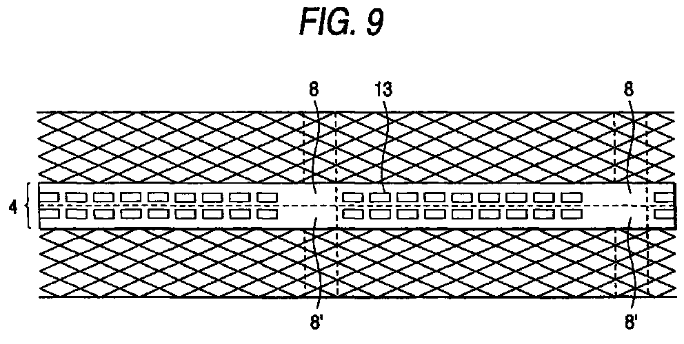
- openings were stamped to provide the shape shown in FIG. 9. If the expanded sheet is cut in the length direction, electrode plates can be taken out two at a time; paraffin as a parting agent of an active material was applied only to a part 8' corresponding to electrode plate lug part of one series of electrode plates.
- the sheet was passed through a pasting machine 5 for filling active material paste 6 into the full face of the sheet.
- pasting paper was applied to the rear and surface of the expanded sheet and roll press was performed for bringing the pasting paper into intimate contact with the active material.
- the expanded sheet was cut to predetermined dimensions to form the state shown in FIG. 23.
- the electrode plate dimensions were 140 mm wide, 400 mm high, 15 mm in lug part width, and 30 mm in lug part height.
- the cut electrode plate was passed through a flash drying furnace 23 (FIG. 24) and was dried at 200°C for one minute, whereby only the surface of the electrode plate was dried. After the electrode plate was passed through the flash drying furnace, the lug part of the electrode plate was parallel to the travel direction.
- the electrode plate whose surface was dried was rotated 90 degrees by a rotating machine 24, making the electrode plate lug part perpendicular to the travel direction of the electrode plate.
- the lug part was ground by a rotating brush (grinding machine 25) for removing the deposited active material.
- the grinding time of the lug part by the grinding machine was changed for testing.
- the active material on an electrode plate lug part 8' to which paraffin was applied before pasting can be completely removed in about a third the time required for removing the active material on an electrode plate lug part 8 to which no treatment was applied, and a metal shine was observed.
- grease and Vaseline were also used for testing, and similar results were provided.
- a parting agent is thus applied to the lug part, whereby the active material removal time can be shortened and the risk of thinning the lug part by grinding it can be lessened.
- the purpose of rotating the electrode plate 90 degrees before passing it through the grinding machine 25 is to align the electrode plate lug parts relative to the grinding machine and grind only the lug parts consecutively so that the active material in other portions is not removed. In doing so, the active material on the lug parts can be removed easily and completely.
- FIG. 25 shows a state in which the active material on the lug part was removed. Then, the electrode plate was cured at 50°C for two days. The post-cured electrode plate and a separator were combined to assemble a 2V-1000Ah battery by a normal method. At the assembling process, lug part weldability did not introduce a problem and workability similar to that of conventional articles was observed.
- the timing of removing the active material on the electrode plate lug part using the grid body of the invention was studied.
- the active material removal timings listed below are possible and thus an experiment was conducted at the timings.
- paraffin was applied to the part which becomes a lug part as a parting agent.
- the lug part placed in the margin of the grid body is taken as an example.
- the discharge performance of a battery using a grid body comprising an expansion portion on both sides of a non-expansion portion formed with a lug part and openings is further enhanced (for example, 1C 10 A discharge duration is increased about 10%) although the grid body can be taken out only one at a time when an expanded sheet is cut in the length direction to provide grid bodies.
- the invention provides an expanded grid body excellent in productivity, voltage characteristic, and life characteristic and a method of efficiently manufacturing an electrode plate from the grid body.
Landscapes
- Chemical & Material Sciences (AREA)
- Chemical Kinetics & Catalysis (AREA)
- Electrochemistry (AREA)
- General Chemical & Material Sciences (AREA)
- Engineering & Computer Science (AREA)
- Manufacturing & Machinery (AREA)
- Cell Electrode Carriers And Collectors (AREA)
- Battery Electrode And Active Subsutance (AREA)
Abstract
Description
| Batteries used in test in First Embodiment | ||
| Battery No. | Positive and Negative Electrode Plates and Content of Grid Bodies corresponding thereto | Remarks |
| A | Expansion Direction: Width direction Grid body: An openings were provided in a non-expansion portion at a predetermined distance below a lug part. (Fig. 10) | Inventive Product |
| B | Expansion Direction: Height direction (Fig. 2) | Conventional Product |
| C | Expansion Direction: Height direction The upper part of a non-expansion portion was widen, and openings were formed. (Fig. 3) | Conventional Product |
| D | Expansion Direction: Height direction A non-expansion portion was provided in an intermediate part of a grid body and openings were formed. (Fig. 4) | Conventional Product |
| E | Expansion Direction: Width direction The width of a non-expansion portion was gradually lessened following a lug part. (Fig. 5) | Conventional Product |
| F | Expansion Direction: Width direction A non-expansion portion was made small, and openings were not formed. (Fig. 12) | Conventional Product |
| G | Expansion Direction: Width direction An openings formed non-expansion portions were increased in the lug part direction (top) and a non-expansion portion width slightly widened. (Fig. 13) | Comparative Product |
| Discharge Test Results of Each Rate | |||||
| Battery No. | 0.1C10A (15A) Discharge Duration (h) | 1C10A (150A) Discharge Duration (min) | 3C10A (450A) Discharge Duration (min) | 3C10A (450A) voltage at fifth sec. of discharge | Condition of Electrode Plate after Test |
| A | 10.37 | 33.63 | 5.58 | 1.78 | No abnormal |
| B | 10.53 | 20.62 | 1.23 | 1.56 | |
| C | 10.42 | 25.67 | 3.58 | 1.64 | |
| D | 10.43 | 26.22 | 1.46 | 1.58 | |
| E | 9.53 | 28.85 | 5.08 | 1.76 | No abnormal |
| F | 10.25 | 32.57 | 4.68 | 1.71 | |
| G | 10.33 | 33.12 | 3.93 | 1.74 |
| 1C10A discharge test result | ||
| Battery using negative electrode with previously cut | Battery using negative electrode with previously cut | |
| Discharge duration (min) | 27.33 | 19.83 |
- 1) Just after pasting: The active material was soft, a rotating brush of a grinding machine was clogged with the active material, and it became hard to remove the active material with time.
- 2) After passing through flash drying furnace: The active material became hard as compared with that just after pasting, and can be easily removed without being caught in the rotating brush of the grinding machine.
- 3) After completion of curing: The active material was hard and it took about twice the time in removing the active material; in addition, unintended parts other than the lug part also peeled off together.
- 4) Just before assembling: Similar result to that in 3) after completion of curing.
Claims (8)
- A lead-acid battery electrode plate manufactured by a process comprising the steps of:(1) consecutively supplying a lead or lead alloy sheet;(2) leaving a part in the vicinity of the center of the sheet as a non-expansion portion and expanding both sides like mesh to form a grid body;(3) filling active material paste into the grid body; and(4) cutting the grid body to predetermined dimensions;
wherein the non-expansion portion forms a current collector part of the electrode plate along an expansion portion in an up and down direction of the electrode plate; one or more openings are made in a part of the non-expansion portion; a part of the non-expansion portion is projected above the position of an upper margin of the cut expansion portion as a current collector lug part; and when the current collector lug part is placed upside, the expansion direction is the width direction of the electrode plate. - The lead-acid battery electrode plate as claimed in claim 1, wherein openings are not made in the current collector lug part or the non-expansion portion in a given portion downward from the position of the upper margin of the cut expansion portion, and the dimensions of the given portion are equal to or greater than mesh major axis dimensions of the expansion section.
- A manufacturing method of a lead-acid battery electrode plate, comprising the steps of:consecutively supplying a lead or lead alloy sheet;leaving a part in the vicinity of the center of the sheet as a non-expansion portion and expanding both sides like mesh to form a grid body, so that the non-expansion portion forms a current collector part of the electrode plate along an expansion portion in an up and down direction of the electrode plate;making one or more openings in a part of the non-expansion portion;filling active material paste into the grid body; andcutting the grid body to predetermined dimensions;
wherein a part of the non-expansion portion is projected above the position of an upper margin of the cut expansion portion as a current collector lug part; and when the current collector lug part is placed upside, the expansion direction is the width direction of the electrode plate. - The lead-acid battery electrode plate manufacturing method as claimed in claim 3, further comprising the step of, after an active material is pasted into the full face containing the non-expansion portion of the grid body, partially removing the active material on a portion corresponding to the current collector lug part for exposing a metal surface.
- The lead-acid battery electrode plate manufacturing method as claimed in claim 4, wherein the step of partially removing the active material on a portion corresponding to the current collector lug part is performed after a surface of the electrode plate is dried and before a curing step.
- The lead-acid battery electrode plate manufacturing method as claimed in claim 4, further comprising the steps of, after the active material is consecutively pasted into the grid bodies concatenated like a belt, separating electrode plates, and subsequently rotating the electrode plate 90 degrees, then partially removing the active material.
- The lead-acid battery electrode plate manufacturing method as claimed in claim 4, further comprising the step of: before pasting the active material, applying a parting agent onto the portion on which the active material is to be removed after pasting.
- A manufacturing method of a lead-acid battery electrode plate as claimed in claim 3, wherein after the grid body is cut to predetermined dimensions, active material paste is pasted into the full face containing the non-expansion portion.
Applications Claiming Priority (6)
| Application Number | Priority Date | Filing Date | Title |
|---|---|---|---|
| JP11013564A JP2000215898A (en) | 1999-01-21 | 1999-01-21 | Lead-acid battery grid |
| JP1356499 | 1999-01-21 | ||
| JP11121052A JP2000311678A (en) | 1999-04-28 | 1999-04-28 | Method for manufacturing electrode plate for lead-acid battery |
| JP12105299 | 1999-04-28 | ||
| JP19989899 | 1999-07-14 | ||
| JP11199898A JP2001028262A (en) | 1999-07-14 | 1999-07-14 | Method for manufacturing electrode plate for lead-acid battery |
Publications (3)
| Publication Number | Publication Date |
|---|---|
| EP1022791A2 true EP1022791A2 (en) | 2000-07-26 |
| EP1022791A3 EP1022791A3 (en) | 2000-11-15 |
| EP1022791B1 EP1022791B1 (en) | 2003-09-24 |
Family
ID=27280321
Family Applications (1)
| Application Number | Title | Priority Date | Filing Date |
|---|---|---|---|
| EP00101188A Expired - Lifetime EP1022791B1 (en) | 1999-01-21 | 2000-01-21 | Electrode plate for lead-acid battery and manufacturing method thereof |
Country Status (3)
| Country | Link |
|---|---|
| US (2) | US6338919B1 (en) |
| EP (1) | EP1022791B1 (en) |
| DE (1) | DE60005413T2 (en) |
Cited By (3)
| Publication number | Priority date | Publication date | Assignee | Title |
|---|---|---|---|---|
| WO2008155540A1 (en) * | 2007-06-19 | 2008-12-24 | Eh Europe Gmbh | A process for making an electrode, an electrode and a battery comprising the electrode |
| CN102157720A (en) * | 2010-12-31 | 2011-08-17 | 东莞市飞新达精密机械科技有限公司 | A method for forming and processing battery pole pieces |
| CN103624158A (en) * | 2013-11-17 | 2014-03-12 | 保定金阳光能源装备科技有限公司 | Lead-acid battery curved plate grid multi-position grading stamping mould |
Families Citing this family (13)
| Publication number | Priority date | Publication date | Assignee | Title |
|---|---|---|---|---|
| JP4831269B2 (en) * | 2000-03-17 | 2011-12-07 | ソニー株式会社 | Battery manufacturing method |
| US7159805B2 (en) | 2002-03-25 | 2007-01-09 | Evanite Fiber Corporation | Methods of modifying fibers |
| US6929858B2 (en) | 2002-03-25 | 2005-08-16 | Squannacook Technologies Llc | Glass fibers |
| US7846574B2 (en) * | 2004-08-27 | 2010-12-07 | Panosonic Corporation | Positive electrode plate for alkaline storage battery and method for producing the same |
| US7280398B1 (en) * | 2006-08-31 | 2007-10-09 | Micron Technology, Inc. | System and memory for sequential multi-plane page memory operations |
| KR20080058772A (en) * | 2006-12-22 | 2008-06-26 | 에스케이에너지 주식회사 | Manufacturing Method of Battery Electrode |
| DE102008055775A1 (en) * | 2008-11-04 | 2010-05-06 | Vb Autobatterie Gmbh & Co. Kgaa | Electrode for a rechargeable battery |
| CN102513443A (en) * | 2011-12-09 | 2012-06-27 | 深圳市雄韬电源科技股份有限公司 | Method for processing punched grids of lead-acid accumulators |
| CN102709507B (en) * | 2012-06-18 | 2014-04-09 | 林子进 | High-lead-ion-energy polar plate |
| DE202012012740U1 (en) * | 2012-03-22 | 2013-10-17 | Vb Autobatterie Gmbh & Co. Kgaa | Plant for the production of electrodes for lead-acid batteries |
| TW201407859A (en) * | 2012-08-15 | 2014-02-16 | Dijiya Energy Saving Technology Inc | Continuous winding method for single core, lithium battery with single core and single core |
| CN106486645A (en) * | 2015-08-24 | 2017-03-08 | 中国科学院金属研究所 | A kind of lead carbon battery negative plate containing network-like material with carbon element and preparation method thereof |
| CN112736366B (en) * | 2020-12-29 | 2023-06-27 | 上海应用技术大学 | Method for cast-welding light metal negative grid lead storage battery busbar |
Family Cites Families (8)
| Publication number | Priority date | Publication date | Assignee | Title |
|---|---|---|---|---|
| US4271586A (en) | 1979-08-27 | 1981-06-09 | General Motors Corporation | Method of making battery plates |
| JPS58133271A (en) | 1982-02-02 | 1983-08-08 | 株式会社東洋クオリティワン | Production of ball |
| JPS5818875A (en) * | 1981-07-24 | 1983-02-03 | Japan Storage Battery Co Ltd | Lead storage battery prepared by use of expanded grids |
| JPS58133271U (en) * | 1982-03-04 | 1983-09-08 | 株式会社ユアサコーポレーション | lead battery |
| JPS60185365A (en) * | 1984-03-01 | 1985-09-20 | Furukawa Battery Co Ltd:The | Manufacture of substrate for storage battery plate |
| JPH02267864A (en) * | 1989-04-07 | 1990-11-01 | Yuasa Battery Co Ltd | Storage battery electrode plate and its manufacture |
| EP0682378A4 (en) * | 1992-12-28 | 1998-04-15 | Yuasa Battery Co Ltd | Expanded net, method for its manufacture, and plate for lead storage battery. |
| US5762654A (en) | 1996-10-08 | 1998-06-09 | Gnb Technologies, Inc. | Method for making lead-acid grids and cells and batteries using such grids |
-
2000
- 2000-01-21 EP EP00101188A patent/EP1022791B1/en not_active Expired - Lifetime
- 2000-01-21 DE DE60005413T patent/DE60005413T2/en not_active Expired - Fee Related
- 2000-01-21 US US09/488,639 patent/US6338919B1/en not_active Expired - Lifetime
-
2001
- 2001-06-13 US US09/878,973 patent/US6385829B2/en not_active Expired - Fee Related
Cited By (5)
| Publication number | Priority date | Publication date | Assignee | Title |
|---|---|---|---|---|
| WO2008155540A1 (en) * | 2007-06-19 | 2008-12-24 | Eh Europe Gmbh | A process for making an electrode, an electrode and a battery comprising the electrode |
| US20100216021A1 (en) * | 2007-06-19 | 2010-08-26 | Rhodri Evans | Electrode plate |
| CN102157720A (en) * | 2010-12-31 | 2011-08-17 | 东莞市飞新达精密机械科技有限公司 | A method for forming and processing battery pole pieces |
| CN102157720B (en) * | 2010-12-31 | 2013-01-30 | 东莞市飞新达精密机械科技有限公司 | Battery pole piece forming processing method |
| CN103624158A (en) * | 2013-11-17 | 2014-03-12 | 保定金阳光能源装备科技有限公司 | Lead-acid battery curved plate grid multi-position grading stamping mould |
Also Published As
| Publication number | Publication date |
|---|---|
| EP1022791B1 (en) | 2003-09-24 |
| DE60005413T2 (en) | 2004-09-16 |
| US6385829B2 (en) | 2002-05-14 |
| US20010042288A1 (en) | 2001-11-22 |
| EP1022791A3 (en) | 2000-11-15 |
| US6338919B1 (en) | 2002-01-15 |
| DE60005413D1 (en) | 2003-10-30 |
Similar Documents
| Publication | Publication Date | Title |
|---|---|---|
| EP1022791B1 (en) | Electrode plate for lead-acid battery and manufacturing method thereof | |
| US9130232B2 (en) | Battery grids and methods for manufacturing same | |
| JP6162136B2 (en) | Battery grid with altered corrosion resistance | |
| CN101569032A (en) | Method for manufacturing battery electrode | |
| EP0902491A1 (en) | Expanded grid for electrode plate of lead-acid battery | |
| JPH10284085A (en) | Grid for lead-acid battery | |
| JPWO2017085917A1 (en) | Electrode plate for power storage device and power storage device including the same | |
| JP3178064B2 (en) | Manufacturing method of electrode plate for lead-acid battery | |
| JP4436464B2 (en) | Lithium ion battery | |
| KR200173954Y1 (en) | Electrode of lithium ion secondary battery | |
| JP5088663B2 (en) | Method for manufacturing wound sealed lead-acid battery | |
| JP3350359B2 (en) | Manufacturing method of positive electrode plate for alkaline storage battery | |
| CN112952101A (en) | Cylindrical lithium ion secondary battery and preparation method thereof | |
| JP3637603B2 (en) | Lead acid battery | |
| JP7236417B2 (en) | Method for manufacturing positive electrode of non-aqueous secondary battery, method for manufacturing non-aqueous secondary battery, and non-aqueous secondary battery | |
| JP3444168B2 (en) | Lead storage battery | |
| JP2984816B2 (en) | How to attach tab to positive plate | |
| JP3658834B2 (en) | Sealed lead acid battery | |
| JP2003132897A (en) | Manufacturing method of expanded electrode plate for positive electrode | |
| JP2576714B2 (en) | Manufacturing method of cathode plate for lead-acid battery | |
| JP2003100301A (en) | Expanded grid for positive electrode and method for producing the same | |
| JP2000215898A5 (en) | ||
| JPH10188995A5 (en) | ||
| JPS63105476A (en) | Manufacture of lithium secondary battery | |
| JPH11354113A (en) | Positive electrode plate for lead storage battery and method for producing the same |
Legal Events
| Date | Code | Title | Description |
|---|---|---|---|
| PUAI | Public reference made under article 153(3) epc to a published international application that has entered the european phase |
Free format text: ORIGINAL CODE: 0009012 |
|
| AK | Designated contracting states |
Kind code of ref document: A2 Designated state(s): DE FR GB |
|
| AX | Request for extension of the european patent |
Free format text: AL;LT;LV;MK;RO;SI |
|
| PUAL | Search report despatched |
Free format text: ORIGINAL CODE: 0009013 |
|
| AK | Designated contracting states |
Kind code of ref document: A3 Designated state(s): AT BE CH CY DE DK ES FI FR GB GR IE IT LI LU MC NL PT SE |
|
| AX | Request for extension of the european patent |
Free format text: AL;LT;LV;MK;RO;SI |
|
| 17P | Request for examination filed |
Effective date: 20001228 |
|
| AKX | Designation fees paid |
Free format text: DE FR GB |
|
| 17Q | First examination report despatched |
Effective date: 20020327 |
|
| GRAH | Despatch of communication of intention to grant a patent |
Free format text: ORIGINAL CODE: EPIDOS IGRA |
|
| GRAH | Despatch of communication of intention to grant a patent |
Free format text: ORIGINAL CODE: EPIDOS IGRA |
|
| GRAA | (expected) grant |
Free format text: ORIGINAL CODE: 0009210 |
|
| AK | Designated contracting states |
Kind code of ref document: B1 Designated state(s): DE FR GB |
|
| REG | Reference to a national code |
Ref country code: GB Ref legal event code: FG4D |
|
| REF | Corresponds to: |
Ref document number: 60005413 Country of ref document: DE Date of ref document: 20031030 Kind code of ref document: P |
|
| PG25 | Lapsed in a contracting state [announced via postgrant information from national office to epo] |
Ref country code: GB Free format text: LAPSE BECAUSE OF NON-PAYMENT OF DUE FEES Effective date: 20040121 |
|
| ET | Fr: translation filed | ||
| PLBE | No opposition filed within time limit |
Free format text: ORIGINAL CODE: 0009261 |
|
| STAA | Information on the status of an ep patent application or granted ep patent |
Free format text: STATUS: NO OPPOSITION FILED WITHIN TIME LIMIT |
|
| GBPC | Gb: european patent ceased through non-payment of renewal fee |
Effective date: 20040121 |
|
| 26N | No opposition filed |
Effective date: 20040625 |
|
| PGFP | Annual fee paid to national office [announced via postgrant information from national office to epo] |
Ref country code: FR Payment date: 20050110 Year of fee payment: 6 |
|
| PG25 | Lapsed in a contracting state [announced via postgrant information from national office to epo] |
Ref country code: FR Free format text: LAPSE BECAUSE OF NON-PAYMENT OF DUE FEES Effective date: 20060131 |
|
| REG | Reference to a national code |
Ref country code: FR Ref legal event code: ST Effective date: 20060929 |
|
| PGFP | Annual fee paid to national office [announced via postgrant information from national office to epo] |
Ref country code: DE Payment date: 20080117 Year of fee payment: 9 |
|
| PG25 | Lapsed in a contracting state [announced via postgrant information from national office to epo] |
Ref country code: DE Free format text: LAPSE BECAUSE OF NON-PAYMENT OF DUE FEES Effective date: 20090801 |