EP1022720A2 - Melody performance training apparatus - Google Patents
Melody performance training apparatus Download PDFInfo
- Publication number
- EP1022720A2 EP1022720A2 EP00100684A EP00100684A EP1022720A2 EP 1022720 A2 EP1022720 A2 EP 1022720A2 EP 00100684 A EP00100684 A EP 00100684A EP 00100684 A EP00100684 A EP 00100684A EP 1022720 A2 EP1022720 A2 EP 1022720A2
- Authority
- EP
- European Patent Office
- Prior art keywords
- data
- actuated
- melody
- cpu
- reading
- Prior art date
- Legal status (The legal status is an assumption and is not a legal conclusion. Google has not performed a legal analysis and makes no representation as to the accuracy of the status listed.)
- Granted
Links
- 230000000994 depressogenic effect Effects 0.000 claims abstract description 48
- 238000000034 method Methods 0.000 claims description 89
- 239000000872 buffer Substances 0.000 description 32
- 230000000881 depressing effect Effects 0.000 description 10
- 238000004519 manufacturing process Methods 0.000 description 6
- 230000000694 effects Effects 0.000 description 4
- 230000001360 synchronised effect Effects 0.000 description 3
- 238000013500 data storage Methods 0.000 description 2
- 238000010586 diagram Methods 0.000 description 2
- 230000005764 inhibitory process Effects 0.000 description 2
- 230000003111 delayed effect Effects 0.000 description 1
- 230000002401 inhibitory effect Effects 0.000 description 1
- 230000003287 optical effect Effects 0.000 description 1
Images






Classifications
-
- G—PHYSICS
- G10—MUSICAL INSTRUMENTS; ACOUSTICS
- G10H—ELECTROPHONIC MUSICAL INSTRUMENTS; INSTRUMENTS IN WHICH THE TONES ARE GENERATED BY ELECTROMECHANICAL MEANS OR ELECTRONIC GENERATORS, OR IN WHICH THE TONES ARE SYNTHESISED FROM A DATA STORE
- G10H1/00—Details of electrophonic musical instruments
- G10H1/0008—Associated control or indicating means
- G10H1/0016—Means for indicating which keys, frets or strings are to be actuated, e.g. using lights or leds
-
- G—PHYSICS
- G10—MUSICAL INSTRUMENTS; ACOUSTICS
- G10H—ELECTROPHONIC MUSICAL INSTRUMENTS; INSTRUMENTS IN WHICH THE TONES ARE GENERATED BY ELECTROMECHANICAL MEANS OR ELECTRONIC GENERATORS, OR IN WHICH THE TONES ARE SYNTHESISED FROM A DATA STORE
- G10H2220/00—Input/output interfacing specifically adapted for electrophonic musical tools or instruments
- G10H2220/021—Indicator, i.e. non-screen output user interfacing, e.g. visual or tactile instrument status or guidance information using lights, LEDs or seven segments displays
- G10H2220/026—Indicator, i.e. non-screen output user interfacing, e.g. visual or tactile instrument status or guidance information using lights, LEDs or seven segments displays associated with a key or other user input device, e.g. key indicator lights
- G10H2220/061—LED, i.e. using a light-emitting diode as indicator
-
- G—PHYSICS
- G10—MUSICAL INSTRUMENTS; ACOUSTICS
- G10H—ELECTROPHONIC MUSICAL INSTRUMENTS; INSTRUMENTS IN WHICH THE TONES ARE GENERATED BY ELECTROMECHANICAL MEANS OR ELECTRONIC GENERATORS, OR IN WHICH THE TONES ARE SYNTHESISED FROM A DATA STORE
- G10H2240/00—Data organisation or data communication aspects, specifically adapted for electrophonic musical tools or instruments
- G10H2240/171—Transmission of musical instrument data, control or status information; Transmission, remote access or control of music data for electrophonic musical instruments
- G10H2240/281—Protocol or standard connector for transmission of analog or digital data to or from an electrophonic musical instrument
- G10H2240/311—MIDI transmission
Definitions
- the present invention relates to melody performance training apparatus and recording mediums, which records a melody performance training program.
- a performance training apparatus which has the navigation function of guiding a performer's performance, is known conventionally.
- light emitting elements such as light emitting diodes are provided in correspondence to the keys of a keyboard.
- the performer is caused to recognize a key to be depressed and a timing of depressing the key by causing a light-emitting element for the key to emit light.
- the performance of the melody is stopped to thereby synchronize the performer's performance with the progress of performance of the melody.
- a melody performance training apparatus comprising a plurality of elements to be actuated for performing a melody, storage means which contains melody data which includes a plurality of pairs of event data representing one of the plurality of elements to be actuated, and corresponding time data representing a timing when the element represented by the event data is to be actuated; data reading means (11) for sequentially reading the plurality of pairs of event data and corresponding time data stored in the storage means; performance specifying means (20), responsive to the data reading means reading event data of one of the plurality of pairs of melody data which represents a particular one of the plurality of elements to be actuated, for specifying the particular element corresponding to the event data, characterized by:
- a recording medium which contains a computer readable program for causing a computer to perform a process which comprises the steps of:
- training a melody performance can be realized in a processor such as a computer such that even when the particular element, specified by the stored melody data, is actuated before the timing when the particular element is to be actuated, performance of the present part of the melody data is synchronized with performance of another part of the melody data and the performer has no feeling that something is wrong.
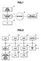
- FIG. 1 illustrates the composition of a system which includes the keyboard device 1, which drives a FD (floppy disk) 2 as storage means which stores melody data to provide MIDI data to a MIDI sound source 3.
- the melody data is received from a melody data sever 5 via a network (telecommunication lines) 4 of the internet.
- FIG. 2 is a block diagram of the keyboard device.
- a CPU 11 of the keyboard device is connected via a system bus to a ROM 12, a RAM 13, a key scan interface 14, a LEDC (LED controller) 15, a FDDC (floppy disk driver controller) 16, a modem 17, and a MIDI interface 18.
- LEDC LED controller
- FDDC floppy disk driver controller
- the ROM 12 contains a melody performance training program executed by the CPU 11.
- the RAM 13 temporarily stores various data processed by the CPU 11.
- the key scan interface 14 is connected to an optical keyboard and switch group 19 to scan the operational state of the group 19 and provides a corresponding signal to the CPU 11.
- the LEDC 15 controls the turning on and off of an LED 20 as light emitting means provided in correspondence to each key, which can be referred to as an element to be actuated, herein.
- the FDDC 16 controls an FDD (floppy disk driver) 21.
- the modem 17 as communication control means includes a network control unit (NCU) (not shown) which controls connection of the modem to the telecommunication line or network 4, and receives and demodulates melody data from the melody data sever 5 in accordance with a reception instruction from the CPU 11.
- NCU network control unit
- the FDDC 16 and FDD 21 record received melody data in the floppy disk 2.
- the MIDI interface 18 delivers to the MIDI sound source 3 the MIDI data created by the CPU 11.
- the status byte is composed of three bits representing the kind of massage and four bits representing a channel number n. For example, "000”, "001", and “100” represent "note off” data, "note on” data, and a program change command which involves a change of tone quality of a melody concerned, respectively, as the kind of channel message.
- FIG. 3B illustrates a plurality of parts of melody data, for example, a melody part, a drum part, a base part and three code parts, specified for each channel.
- the melody part is generally specified as a part for performance guidance.
- the melody part is composed of alternately arranged time data and event data for each of addresses in an address register AD.
- the event data is composed of note on or off data and a channel number as status bytes, and note data (representing a key number) and velocity data as data bytes.
- An end address of the melody part contains END data.
- FIG. 5 shows a main flow of the flowchart which includes a looping operation which repeats after a predetermined initializing process (step A1), a switch process (step A2), a key guiding process (step A3), a key depressing process (step A4), a time counting process (step A5), an outputting process (step A6), a receiving process (step A7), and another process (step A8).
- FIG. 6 is a flowchart of the switch process (step A2) of the main flow of FIG. 5.
- the CPU 11 scans the switch group of FIG. 2, and effects a mode select switch process (step B1), a start switch process (step B2), a receiving process (step B3) and another switch process (step B4) and then returns its control to the main flow of FIG. 5.
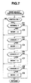
- FIG.7 shows a flowchart of the mode select switch process (step B1) of FIG. 6.
- the CPU 11 determines whether any one of the mode select switches which include a normal switch, a lesson 1 switch, a lesson 2 switch and a lesson 3 switch is turned on (step C1). If otherwise, the CPU 11 terminates this process. If any one of the switches is turned on, the CPU 11 effects a process corresponding to the turning on of the mode select switch.
- the CPU 11 determines whether the normal switch has been turned on (step C2). If it has been turned on, the CPU 11 sets a mode register MODE to "0" (step C3). Then, the CPU 11 determines whether the lesson 1 switch has been turned on (step C4). If it has been turned on, the CPU 11 sets the mode register MODE to "1" (step C5). The CPU 11 then determines whether the lesson 2 switch has been turned on (step C6). If it has been turned on, the CPU 11 sets the mode register MODE to "2" (step C7). The CPU 11 then determines whether the lesson 3 switch has been turned on (step C8). If it has been turned on, the CPU 11 then sets the mode register MODE to "3" (step C9).
- the value "3" of the mode register MODE indicates a mode in which melody data is read automatically irrespective of the performance and in which a musical sound of the melody data is produced when a corresponding guided key is depressed.
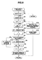
- FIG. 8 is a flowchart indicative of the start switch process (step B2) as a part of the switch process of FIG. 6.
- the CPU 11 determines whether the start switch has been turned on (step D1). If otherwise, the CPU 11 terminates this process. If it has been turned on, the CPU 11 inverts a start flag STF (step D2), and then determines whether the STF is "1" (step D3).
- the CPU 11 sets an address register AD to "0" or a head address of the melody data, and a register STATUS to "1" (step D4).
- the value of the register STATUS is set in the key depressing process to be described later.
- the value of the register STATUS is "1” it is meant that a timing of depressing a key coincides with a timing of starting to produce a musical sound of the melody data concerned.
- the value of the register STATUS is "2”, it is meant that no key is depressed even after the timing of starting to produce a musical sound of the melody data has passed or that the timing of depressing the key is delayed.
- the value of the register STATUS is set to "3”, it is meant that the key has been depressed before the timing of starting to produce a musical sound of the melody data comes or that the timing of depressing the key is too early.
- step D4 the CPU 11 stores data representing the present time in a register ST (step D5), and then sets "0" in a time register T (step D6).
- the CPU 11 sets the time data in the register ⁇ T (step D10).
- step D12 After decrementing the address AD in step D9, or setting time data in the register ⁇ T in step D10, the CPU 11 adds the value of the register ⁇ T to the value of the time register T for updating purposes (step D11). Then, the CPU 11 releases the inhibition of timer interrupt (step D12).
- step D3 When the start flag STF is zero in step D3, the CPU 11 instructs all the channels to mute the musical sounds, excluding a melody channel (step D13), and inhibits the timer interrupt (step D14).
- the CPU 11 After releasing the inhibition of the timer interrupt in step D12 or inhibiting the timer interrupt in D14, the CPU 11 terminates this process, and then returns its control to the switch process of FIG. 6.
- FIG. 9 shows a flowchart of the reception switch process (step B3) as a part of the switch process, in which the CPU 11 determines whether the reception switch has been turned on (step E1). If otherwise, the CPU 11 terminates this process. If it is turned on, the CPU 11 sets a reception flag ZF to "1" (step E2), terminates this process and then returns its control to the switch step of FIG. 6.
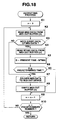
- FIGS. 11-13 show a flowchart of the guide A process (step F2) of FIG. 10, in which the CPU 11 determines whether the start flag STF is 1 (step G1). If it is zero, which indicates that the performance is at a stop, the CPU 11 terminates this process. If the start flag STF is 1, the CPU 11 determines whether the value of the register STATUS is 2 (step G2). If it is 2, it is meant that no key is depressed although the timing of starting to produce a musical sound concerned has come. In that case, a wait mode is set which includes waiting key depression, and the CPU 11 then terminates this process.
- step G2 the CPU 11 compares the present time and the sum of the time values in the registers ST and T or the timing when the musical sound is started to be produced (step G3). If the present time has not reached the timing when the musical sound is started to be produced, the CPU 11 then terminates this process.
- the CPU 11 increments the value of the address register AD (step G4). Then, the CPU 11 determines whether the value of the address register AD is END (step G5). If otherwise, the CPU 11 determines whether data at an address indicated by a value in the address register AD in the melody data storage area of the RAM 13 is time data (step G6). If it is time data, the CPU 11 determines whether the value of the mode register MODE is 1, which means that a musical sound is produced even when any key mode is depressed (step G7). If otherwise, the CPU 11 terminates this process.
- the CPU 11 determines whether the value of the register STATUS is 3 or 1 (step G8). If the value of the register STATUS is 3, the CPU 11 sets a minimum time contained in the MIDI data in the register ⁇ T (step G9). If the value of the register STATUS is 1, the CPU 11 sets data at the address indicated by the value in the address register AD in the register ⁇ T (step G10). After step G9 or G10, the CPU 11 adds the value of the time register T to the value of the register ⁇ T, terminates this process and then returns its control to the key guiding process of FIG. 10.
- step G5 When the value in the address register AD is END in step G5, the CPU 11 instructs the sound source 3 and the LEDC 15 to mute the musical sound and stop light emission, respectively (step G12). The CPU 11 then inhibits the timer interrupt (step G13), resets the start flag STF to zero (step G14), and then terminates this process.
- step G6 the CPU 11 determines whether the read data is note event data of the MIDI data in the flow of FIG. 12 (step G15). If it is note event data, the CPU 11 determines whether it is "note on” data (step G16). If it is "note on” data, the CPU 11 sets pitch data of the MIDI data in a register NOTE (step G17), and then causes an LED of a key corresponding to the value of the register NOTE to emit light (step G18).
- the CPU 11 determines whether the value of the register STATUS is 3 (step G19). If it is not 3 but 1, the CPU 11 changes the value of the register STATUS to 2 (step G20), and then terminates this process. That is, after causing the LED to emit light to guide the depression of a corresponding key, and when the value of the register STATUS is 1, the CPU 11 changes the value of the register STATUS to 2, and stops reading out the melody data until the key is depressed.
- the CPU 11 changes the value of the register STATUS to 1 (step G21), and creates MIDI data based on a value of a register VOLUME (step G22). That is, after causing the LED to emit light to guide the depression of a corresponding key, and the value of the register STATUS is 3, a volume value of the MIDI data is minimum. The CPU 11 restores the original volume value and creates corresponding MIDI data.
- the CPU 11 determines whether it is “note off” data (step G23). If it is "note off” data, the CPU 11 sets pitch data of the MIDI data in the register NOTE (step G24), turns off an LED for a key corresponding to the value of the register NOTE (step G25), shifts its control to step G4 of FIG. 11, where the CPU 11 increments the value of the address register AD, and then repeats the above-mentioned steps concerned.
- the CPU 11 determines whether the read data is volume event data (velocity data) of the MIDI data (step G26). If it is volume event data, the CPU 11 sets the volume value of the MIDI data in the register VOLUME (step G27).
- the CPU 11 determines whether the value of the register STATUS is 1 or 3 (step G28). If it is 1, the CPU 11 changes the volume value of the MIDI data to the value of the register VOLUME (step G29) or returns the volume value of the MIDI data to its original value (actually, step G29 implies NOP).
- the CPU 11 sets the volume value of the MIDI data to a minimum value (step G30). The minimum value is a very small volume value which we can hardly hear or alternatively may be zero.
- the CPU 11 determines whether a MIDI OUT buffer (n) specified by the pointer n is empty (step G32). If it is not empty, the CPU 11 increments the value of the pointer n (step G33), and determines whether n has exceeded a predetermined number (step G34). If the value of the pointer n has not exceeded the predetermined number, the CPU 11 determines in step G32 whether the MIDI OUT buffer (n) is empty.
- the CPU 11 stores the MIDI data in an event area of MIDI OUT buffer (n) (step G35).
- the CPU 11 also stores data representing the present time in a register WTIME (step G36), and also time data in the register WTIME or the present time in a time area of the MIDI OUT buffer (n) (step G37). Then or when the value of the pointer n has exceeded the predetermined number in step G34, the CPU 11 shifts its control to step G4 of FIG. 11, where it increment the value of the address register AD.
- FIGS. 14 and 15 together form a flowchart of the guide B process (step F4) in the key guiding process of FIG. 10.
- the CPU 11 determines whether the start flag STF is 1 (step H1). If it is zero, which indicates a performance stop state, the CPU 11 terminates this process. If the flag STF is 1, the CPU 11 determines whether the present time coincides with the sum of the time values of the registers ST and T or the timing when a musical sound starts to be produced (step H2). If otherwise, the CPU 11 terminates this process.
- the CPU 11 increments the value of the address register AD (step H3), and then determines whether the value of the address register AD is END (step H4). If otherwise, the CPU 11 determines whether data at the address indicated by the value in the address register AD is time data (step H5). If it is time data, the CPU 11 sets in the register ⁇ T the data at the address indicated by the value of the address register AD in the RAM 13 (step H6). The CPU 11 then adds the value of the register ⁇ T to the value of the register T (step G7), terminates this process, and then returns its control to the key guiding process of FIG. 10.
- step H4 When the data at the address indicated by the value of the address register AD is END in step H4, the CPU 11 instructs the sound source and the LEDC 15 to mute the musical sounds and stop light emission, respectively (step H8). The CPU 11 then inhibits the timer interrupt (step H9), resets the start flag STF to zero (step H10), terminates this process and then returns its control to the key guiding process of FIG. 10.
- step H5 the CPU 11 determines whether the read data is note event data of the MIDI data (step H11). If it is note event data, the CPU 11 determines whether it is "note on” data (step H12). If it is "note on” data, the CPU 11 sets pitch data of the MIDI data in the register NOTE (step H13), and then causes an LED of a key corresponding to the value of the register NOTE to emit light (step H14).
- the CPU 11 sets the pitch data of the MIDI data in the register NOTE (step H15), and then turns off an LED for a key corresponding to the pitch data of the MIDI data in the register NOTE (step H16).
- step H14 or H16 After turning on or off the corresponding LED in step H14 or H16, the CPU 11 shifts its control to step H3, where it increments the value of the register AD, and then repeats the above-mentioned steps concerned.
- step H11 After the data read out in step H11 is not note event data of the MIDI data, that is, is "key on event" data, the CPU 11 sets to zero the value of the pointer n which specifies a channel of a MIDI OUT buffer (step H17 of FIG. 15), increments the pointer n while writing MIDI data to MIDI OUT buffer (n). In this case, the CPU 11 determines whether the MIDI OUT buffer (n) specified by the value of the pointer n is empty (step H18). If it is not empty, the CPU 11 increments the value of the pointer n (step H19), and determines whether the value of the pointer n has exceeded a predetermined number (step H20). If the value of the pointer n has not exceeded the predetermined number, the CPU 11 determines in step H18 whether the MIDI OUT buffer (n) is empty.
- the CPU 11 stores the MIDI data in the event area of MIDI OUT buffer (n) (step H21).
- the CPU 11 also stores the present time data in a register WTIME (step H22), and also time data in the register WTIME (or the present time) in the time area of the MIDI OUT buffer (n) (step H29). Then or when the value of the pointer n has exceeded the predetermined number in step H29, the CPU 11 shifts its control to step H3 of FIG. 11, where it increment the value of the address register AD.
- FIGS. 16 and 17 together form a flowchart of a key depressing step A4 of the main flow of FIG. 5.
- the CPU 11 determines whether the status of any key has changed (step J1). If otherwise, the CPU 11 returns its control to the main flow. If the key has been depressed, the CPU 11 stores pitch data on the key in a register KEY (step J2), and also velocity data representing the intensity of depression of the key in a register VELOCITY (step J3).
- the CPU 11 determines whether the value of the mode register MODE is 1 or 2 (step J4) or whether the set mode is a key depression wait mode. When the value of the register MODE is 1 or 2, the CPU 11 then further determines whether the value of the mode register MODE is 2 (step J5) or whether the set mode is a mode in which a correct key guided so to be depressed is waited. If the value of the mode register MODE is 2, the CPU 11 determines whether the number of the key to be depressed and represented by the register KEY coincides with note data of the MIDI data represented by the value of the register NOTE (step J6).
- the CPU 11 determines whether the present time has not reached the sum of the time data of the register ST and T (step J7) or whether the present time has not reached the timing when the musical sound starts to be produced.
- the CPU 11 sets 1 to the value of the register STATUS, subtracts the sum of the time data of the register ST and T from the present time, and stores the difference in a difference register S (step J9), and adds the value of the register S to the time data of the register ST (step J10) to update the value of the register ST, and then creates MIDI data for a melody channel concerned (step J11).
- step J1 When the key is released from its depression in step J1, the CPU 11 stores in the register KEY data representing the pitch of the musical sound produced last by depression of the key before the key was released (step J14), sets the value of the register VELOCITY to zero (step J15), and creates MIDI data of the melody (step J11).
- step J4 When the value of the register MODE is neither 1 or 2, but 3 in step J4, or when the value of the register KEY does not coincide with the value of the register NOTE in step J6, that is, when a key different from the key which the user was guided to depress has been depressed or the value of the register MODE is not 1 in step J12, the CPU 11 creates MIDI data of the melody (step J11).
- the CPU 11 sets the value of the pointer n which specifies the MIDI OUT buffer to zero (step J16), increments the value of the pointer n while setting the MIDI data in MIDI OUT buffer (n). That is, the CPU 11 determines whether the MIDI OUT buffer (n) is empty (step J17). If otherwise, the CPU 11 increments the value of the pointer n (step J18), and then determines whether the value of the pointer n has exceeded a predetermined number (step J19). If otherwise, the CPU 11 shifts its control to step J17, where it determines whether the MIDI OUT buffer (n) is empty.
- the CPU 11 stores the MIDI data in an event area of the MIDI OUT buffer (n) (step J20).
- the CPU 11 stores the present time data in the register WTIME (step J21), and also stores the present time data in the register WTIME in the time area of the MIDI OUT buffer (n) (step J22).
- the CPU 11 determines whether the value of the register STATUS is 3 (step J23). If otherwise, the CPU 11 terminates this process. That the value of the register STATUS is 3 implies that a key has been depressed before the timing when the musical sound for the MIDI data starts to be produced has come. Thus, the CPU 11 effects a process for feeding the MIDI data rapidly.
- the CPU 11 creates MIDI data in which the volume value is minimum (step J24), sets to zero the value of the pointer n which specifies a MIDI OUT buffer (step J25), and then increments the value of the pointer n while storing the created MIDI data in the MIDI OUT buffer (n). Then, the CPU 11 determines whether the MIDI OUT buffer (n) specified by the value of the pointer n is empty (step J26). If otherwise, the CPU 11 increments the value of the pointer n (step J27), and determines whether the value of the pointer n has exceeded the predetermined number (step J28). If otherwise, the CPU 11 determines in step J26 whether the MIDI OUT buffer (n) is empty.
- the CPU 11 stores the MIDI data in the event area of the MIDI OUT buffer (n) (step J29).
- the CPU 11 further stores the present time data in the register WTIME (step J30), and also stores the present time data in the register WTIME in the time area of the MIDI OUT buffer (n) (step J31). Then, or when the value of the pointer n has exceeded the predetermined number in step J28, the CPU 11 then terminates this process and returns its control to the flow of FIG. 5.
- FIG. 18 is a flowchart of the outputting process (step A6) of the flow of FIG. 5.
- the CPU 11 sets the pointer specifying a MIDI OUT buffer to zero representing the head address of the buffer (step K1), and increments the value of the pointer n while effecting the following outputting process. That is, the CPU 11 reads out MIDI data from the MIDI OUT buffer (n) specified by the value of the pointer n (step K2), and then determines whether the read data is "note event" data of the MIDI data (step K3).
- the CPU 11 reads out time data in the register WTIME for the "note event” data from the MIDI OUT buffer (n) (step K4), subtracts the time in the register WTIME from the present time, sets a time difference as the result of the subtraction in a register D (step K5), and then determines whether the value of the register D has exceeded the predetermined value (step K6).
- the CPU 11 When the value of the register D has exceeded the predetermined value or when the MIDI data read out in step K3 is not "note event" data but volume data, the CPU 11 provides the MIDI data to the MIDI OUT device (the MIDI sound source 3 of FIG. 1) (step K7), and then empties the MIDI OUT buffer (n) (step K8). Then, or when the value of the register D is smaller than the predetermined value in step K6, the CPU 11 increments the value of the pointer n (step K9), and then determines whether the value of the pointer n has exceeded the predetermined value (step K10). It otherwise, the CPU 11 shifts its control to step K2, where it retreats a looping process involving steps K2-K10. When the value of the pointer n has exceeded the predetermined number, the CPU 11 terminates this process and then returns its control to the start of the main flow of FIG. 5.
- FIG. 19 is a flowchart of the receiving process (step A7) of the main flow.
- the CPU 11 determines whether the reception flag ZF is 1 (step L1). If the flag ZF is zero, the CPU 11 terminates this process.
- the flag ZF is 1, which represents a request for an access to the melody data server 5
- the CPU 11 sets the value of the address register AD to zero (step L2), and then increments the value of the address register AD while effecting the following looping process.
- the CPU 11 determines through the modem 17 whether MIDI data has been received (step L3). If it has been received, the CPU 11 stores the MIDI data at a location specified by the value of the address register AD (step L4), increments the value of the address register AD, and then specifies a next location (step L5). Then, the CPU 11 determines whether the reception of MIDI data has been terminated (step L6). If otherwise, the CPU 11 shifts its control to step L3, where it determines whether MIDI data has been received.
- the performer can perform the melody at a proper tempo without feeling that something is wrong, and can synchronize his or her performance of the melody with performance of another part for the melody.
- the CPU 11 controls the musical sound producing conditions based on control data contained in the melody data and rapidly fed and read out by the time when the timing comes, it processes the control data like control data read out in a general reading manner.
- the rapidly fed and read out melody data contains a program change command which changes a tone quality of the musical sound concerned during the time period when the melody data was rapidly fed and read out
- the CPU 11 changes the tone quality of the musical sound in accordance with the MIDI data after the time period ends.
- the CPU 11 changes to a minimum the volume of the musical sound produced in the time period when the melody data is rapidly fed and read to thereby suppress a noisy sound in the period.
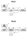
- keyboard device which includes the modem 17, FDDC 16 and FDD 21 as shown in FIGS. 1 and 2, has been illustrated, the present invention is not limited to the embodiment. A system of another embodiment is shown in FIGS. 20 and 21.
- the CPU 11 causes the relevant melody data to be rapidly fed and read in a time period between the time when the key was depressed and the time when the timing at which the musical sound starts to be produced comes to be rapidly fed and read out.
- ROM 12 of the keyboard device 1 is illustrated as containing a melody performance training program to thereby execute a melody performance training process
- a floppy disk, a CD or another recording medium may contain a melody performance training program to cause an information processor such as a general personal computer to perform the program.
- a FD 107 contains a melody performance training program.
- a personal computer 106 drives the FD 107 to execute the melody performance-training program.
- the personal computer 106 includes a modem (not shown) to communicate with a network 4, and receives MIDI data from a melody data sever 5.
- the personal computer 106 also sends/receives commands/MIDI data to/from a keyboard device 101 through a serial interface 103.
- the FD 107 is connected via a telecommunication line to an external device, and contains a performance training program which includes the steps of receiving melody data containing event data on production of a musical sound, and time data indicative of a timing at which the musical sound of the event data starts to be produced; storing the received melody data in a predetermined storage device; reading the melody data stored in the storage device; guiding a key to perform the event data read out by the data reading step based on the event data; stopping the reading of the melody data until a key is depressed when the key is not depressed after the timing at which a musical sound of the event data starts to be produced has elapsed; and when the key is operated before the timing at which the musical sound starts to be produced comes, rapidly feeding the relevant melody data to be fed and read in a time period between the time when the key was depressed and the time when the timing at which the musical sound starts to be produced comes to be fed and read.
- a performance training program which includes the steps of receiving melody data containing event data on production of a musical sound,
- the personal computer 106 When melody data is recorded beforehand in the FD 107, the personal computer 106 directly reads the melody data.
- the FD 107 contains a program which includes the steps of reading from predetermined storage means melody data containing event data on the production of a musical sound and time data indicative of a timing when the musical sound of the event data starts to be produced; guiding a key to perform the event data read out by the data reading step based on the event data; stopping the reading of the melody data until a key is depressed when the key is not depressed after the timing at which the musical sound starts to be produced has elapsed; and when the key is operated before the timing at which the musical sound starts to be produced comes, rapidly feeding the relevant melody data to be fed and read in a time period between the time when the key was depressed and the time when the timing at which the musical sound starts to be produced comes to be fed and read.
Landscapes
- Physics & Mathematics (AREA)
- Engineering & Computer Science (AREA)
- Acoustics & Sound (AREA)
- Multimedia (AREA)
- Electrophonic Musical Instruments (AREA)
- Auxiliary Devices For Music (AREA)
Abstract
Description
characterized by:
Claims (6)
- A melody performance training apparatus comprising a plurality of elements (19) to be actuated for performing a melody, storage means (13) which contains melody data which includes a plurality of pairs of event data representing one of the plurality of elements to be actuated, and corresponding time data representing a timing when the element represented by the event data is to be actuated; data reading means (11) for sequentially reading the plurality of pairs of event data and corresponding time data stored in the storage means; performance specifying means (20), responsive to the data reading means reading event data of one of the plurality of pairs of melody data which represents a particular one of the plurality of elements to be actuated, for specifying the particular element corresponding to the event data,
characterized by:reading control means (steps F2, A4), responsive to the particular element being not actuated even when the timing at which the particular element is to be actuated has come, the timing being represented by the time data corresponding to the event data read out by said data reading means, for stopping the data reading means (11) from reading the remaining portion of the melody data until the particular element is actuated, and responsive to the particular element being actuated before the timing when the particular element is to be actuated comes, for causing the reading means to rapidly read a relevant portion of the melody data to be read in a time period between the time when the particular element was depressed and the time when the timing at which the particular element is to be actuated. - The melody performance training apparatus according to claim 1, wherein said reading control means (steps F2, A4) comprises means (CPU 11; step J6) for determining whether the actuated element is the same as that specified by said performance specifying means.
- The melody performance training apparatus according to claim 1, wherein said storage means (13) further contains as the melody data volume control event data for controlling a volume of a musical sound to be produced, and wherein said reading control means (CPU 11; steps F2, A4) comprises volume control means (CPU 11; steps G26-G30), responsive to said data reading means (11) reading the volume control event data in a time period between the time when the particular element was actuated and the time when the timing at which the particular element is to be actuated, for changing the contents of the read volume control event data so as to minimize a volume of the musical sound to be produced.
- A recording medium which contains a computer readable program for causing a computer to perform a process which comprises the steps of:sequentially reading a plurality of pairs of event data representing one of a plurality of elements to be actuated and corresponding time data representing one of a plurality of elements (15) to be actuated for performing a melody, and corresponding time data representing a timing when the element represented by the event data is to be actuated, the plurality of pairs of event data and corresponding time data composing melody data, from storage means (13) which contains the melody data (steps A4, F2);in response to the data reading step (steps A4, F2) reading event data which represents a particular one of the plurality of elements to be actuated, specifying the particular element (steps G16-G18); andin response to the particular element being not actuated even when a timing at which the particular element is to be actuated has come, the timing being represented by the time data corresponding to the event data read out in the data reading step, stopping the reading step from reading the remaining portion of the melody data until the particular element is actuated, and in response to the particular element being actuated before the timing when the particular element is to be actuated, causing the reading means to rapidly feed a relevant portion of the melody data to be read in a time period between the time when the particular element was actuated and the time when the timing at which the particular element is to be actuated (steps G2, G7-G11, G26-G30).
- The recording medium according to claim 4, further comprising the step of determining whether said actuated element is identical to that specified in the performance specifying means (J6).
- The recording medium according to claim 4, wherein said storage means (13) further contains as the melody data volume control event data for controlling a volume of the musical sound to be produced, and wherein said reading control step( steps G2, G7-G11, G26-G30) comprises volume control step (steps G26-G30), responsive to the reading step (steps A4, F2) reading the volume control event data causing the reading means to rapidly feed a relevant portion of the melody data to be read in the time period between the time when the particular element was actuated and the time when the timing at which the particular element is to be actuated, for changing the contents of the read volume control event data so as to minimize a volume of the musical sound to be produced.
Applications Claiming Priority (2)
| Application Number | Priority Date | Filing Date | Title |
|---|---|---|---|
| JP1106799 | 1999-01-19 | ||
| JP01106799A JP3788085B2 (en) | 1999-01-19 | 1999-01-19 | Performance learning apparatus and recording medium on which performance learning processing program is recorded |
Publications (3)
| Publication Number | Publication Date |
|---|---|
| EP1022720A2 true EP1022720A2 (en) | 2000-07-26 |
| EP1022720A3 EP1022720A3 (en) | 2000-08-09 |
| EP1022720B1 EP1022720B1 (en) | 2005-06-01 |
Family
ID=11767654
Family Applications (1)
| Application Number | Title | Priority Date | Filing Date |
|---|---|---|---|
| EP00100684A Expired - Lifetime EP1022720B1 (en) | 1999-01-19 | 2000-01-13 | Melody performance training apparatus |
Country Status (4)
| Country | Link |
|---|---|
| US (1) | US6180865B1 (en) |
| EP (1) | EP1022720B1 (en) |
| JP (1) | JP3788085B2 (en) |
| DE (1) | DE60020416T2 (en) |
Cited By (1)
| Publication number | Priority date | Publication date | Assignee | Title |
|---|---|---|---|---|
| CN102663900A (en) * | 2012-03-13 | 2012-09-12 | 深圳市迪瑞德科技有限公司 | Input device for early education, display device for early education and method for guide study |
Families Citing this family (10)
| Publication number | Priority date | Publication date | Assignee | Title |
|---|---|---|---|---|
| US6372975B1 (en) * | 1995-08-28 | 2002-04-16 | Jeff K. Shinsky | Fixed-location method of musical performance and a musical instrument |
| US6342663B1 (en) * | 1999-10-27 | 2002-01-29 | Casio Computer Co., Ltd. | Musical performance training apparatus and record medium with musical performance training program |
| JP4052029B2 (en) * | 2002-06-17 | 2008-02-27 | ヤマハ株式会社 | Musical sound generator, plucked instrument, performance system, musical sound generation control method and musical sound generation control program |
| US7665019B2 (en) * | 2003-09-26 | 2010-02-16 | Nbor Corporation | Method for recording and replaying operations in a computer environment using initial conditions |
| JP4320782B2 (en) * | 2006-03-23 | 2009-08-26 | ヤマハ株式会社 | Performance control device and program |
| US7579541B2 (en) * | 2006-12-28 | 2009-08-25 | Texas Instruments Incorporated | Automatic page sequencing and other feedback action based on analysis of audio performance data |
| CN106128437B (en) * | 2010-12-20 | 2020-03-31 | 雅马哈株式会社 | Electronic musical instrument |
| US8723011B2 (en) * | 2011-04-06 | 2014-05-13 | Casio Computer Co., Ltd. | Musical sound generation instrument and computer readable medium |
| JP5742592B2 (en) * | 2011-08-29 | 2015-07-01 | カシオ計算機株式会社 | Musical sound generation device, musical sound generation program, and electronic musical instrument |
| JP5732982B2 (en) * | 2011-04-06 | 2015-06-10 | カシオ計算機株式会社 | Musical sound generation device and musical sound generation program |
Family Cites Families (12)
| Publication number | Priority date | Publication date | Assignee | Title |
|---|---|---|---|---|
| US3744366A (en) | 1972-02-29 | 1973-07-10 | J Delcastillo | Indicating head for use with a keyboard instrument teaching device |
| US3885490A (en) | 1973-02-01 | 1975-05-27 | Cecil F Gullickson | Single track sight and sound musical instrument instruction device |
| US3958487A (en) | 1975-02-18 | 1976-05-25 | Abraham Goldman | Teaching device for musical instruments |
| US4040324A (en) | 1976-04-12 | 1977-08-09 | Harry Green | Chord indicator for instruments having organ and piano-type keyboards |
| IT1113061B (en) | 1978-02-21 | 1986-01-20 | S I El Spa Soc Ind Elettronich | ELECTRONIC APPARATUS FOR MUSIC TEACHING AND READING |
| US4314499A (en) | 1978-04-24 | 1982-02-09 | Donald Olsen | Musical instruments facilitating teaching, composing and improvisation |
| US4331062A (en) | 1980-06-02 | 1982-05-25 | Rogers Allen E | Visual note display apparatus |
| US4366741A (en) | 1980-09-08 | 1983-01-04 | Musitronic, Inc. | Method and apparatus for displaying musical notations |
| US4437378A (en) | 1981-03-30 | 1984-03-20 | Casio Computer Co., Ltd. | Electronic musical instrument |
| JPS61176987A (en) | 1985-01-31 | 1986-08-08 | ヤマハ株式会社 | Key display unit for electronic musical instrument |
| JP2623809B2 (en) | 1989-01-19 | 1997-06-25 | ヤマハ株式会社 | Automatic key press indicating device |
| JP2707853B2 (en) | 1991-03-01 | 1998-02-04 | ヤマハ株式会社 | Key press indicating device |
-
1999
- 1999-01-19 JP JP01106799A patent/JP3788085B2/en not_active Expired - Fee Related
-
2000
- 2000-01-10 US US09/480,505 patent/US6180865B1/en not_active Expired - Lifetime
- 2000-01-13 EP EP00100684A patent/EP1022720B1/en not_active Expired - Lifetime
- 2000-01-13 DE DE60020416T patent/DE60020416T2/en not_active Expired - Lifetime
Cited By (1)
| Publication number | Priority date | Publication date | Assignee | Title |
|---|---|---|---|---|
| CN102663900A (en) * | 2012-03-13 | 2012-09-12 | 深圳市迪瑞德科技有限公司 | Input device for early education, display device for early education and method for guide study |
Also Published As
| Publication number | Publication date |
|---|---|
| DE60020416T2 (en) | 2005-11-10 |
| EP1022720B1 (en) | 2005-06-01 |
| JP3788085B2 (en) | 2006-06-21 |
| JP2000206965A (en) | 2000-07-28 |
| US6180865B1 (en) | 2001-01-30 |
| DE60020416D1 (en) | 2005-07-07 |
| HK1030829A1 (en) | 2001-05-18 |
| EP1022720A3 (en) | 2000-08-09 |
Similar Documents
| Publication | Publication Date | Title |
|---|---|---|
| EP1022720B1 (en) | Melody performance training apparatus | |
| WO1997026645A1 (en) | Keyboard musical instrument equipped with keyboard range display | |
| JP2743680B2 (en) | Automatic performance device | |
| EP1130571B1 (en) | Musical instrument equipped with synchronizer for plural parts of music | |
| US4662261A (en) | Electronic musical instrument with autoplay function | |
| EP0192974B1 (en) | Key depression indicating device for electronic musical instrument | |
| HK1030829B (en) | Melody performance training apparatus | |
| US20070119291A1 (en) | Musical performance training device and recording medium for storing musical performance training program | |
| JPH07319458A (en) | Electronic musical instrument | |
| JPH0259474B2 (en) | ||
| JP3551014B2 (en) | Performance practice device, performance practice method and recording medium | |
| EP1039430A2 (en) | Performance training apparatus, and recording mediums which prestore a performance training program | |
| JP3845761B2 (en) | Performance learning apparatus and storage medium storing performance learning processing program | |
| JPH08248955A (en) | Key touch instructing device | |
| JP2001195065A (en) | Unit and method for control | |
| JPH08335079A (en) | Electronic keyed instrument | |
| JP4158502B2 (en) | Musical performance device and musical performance processing program | |
| JP2001195061A (en) | Method and device for synchronous control | |
| JP3609045B2 (en) | Automatic performance device | |
| JP2000081882A (en) | Operation instructing device | |
| JP2001242867A (en) | Musical sound controller | |
| JP2003122355A (en) | Electronic musical instrument | |
| JP4172335B2 (en) | Automatic accompaniment generator and program | |
| JP2004205892A (en) | Performance device and performance processing program | |
| JP2770770B2 (en) | Electronic musical instrument |
Legal Events
| Date | Code | Title | Description |
|---|---|---|---|
| PUAI | Public reference made under article 153(3) epc to a published international application that has entered the european phase |
Free format text: ORIGINAL CODE: 0009012 |
|
| PUAL | Search report despatched |
Free format text: ORIGINAL CODE: 0009013 |
|
| 17P | Request for examination filed |
Effective date: 20000113 |
|
| AK | Designated contracting states |
Kind code of ref document: A2 Designated state(s): DE FR GB IT |
|
| AX | Request for extension of the european patent |
Free format text: AL;LT;LV;MK;RO;SI |
|
| AK | Designated contracting states |
Kind code of ref document: A3 Designated state(s): AT BE CH CY DE DK ES FI FR GB GR IE IT LI LU MC NL PT SE |
|
| AX | Request for extension of the european patent |
Free format text: AL;LT;LV;MK;RO;SI |
|
| AKX | Designation fees paid |
Free format text: DE FR GB IT |
|
| 17Q | First examination report despatched |
Effective date: 20040629 |
|
| GRAP | Despatch of communication of intention to grant a patent |
Free format text: ORIGINAL CODE: EPIDOSNIGR1 |
|
| GRAS | Grant fee paid |
Free format text: ORIGINAL CODE: EPIDOSNIGR3 |
|
| GRAA | (expected) grant |
Free format text: ORIGINAL CODE: 0009210 |
|
| AK | Designated contracting states |
Kind code of ref document: B1 Designated state(s): DE FR GB IT |
|
| REG | Reference to a national code |
Ref country code: GB Ref legal event code: FG4D |
|
| REF | Corresponds to: |
Ref document number: 60020416 Country of ref document: DE Date of ref document: 20050707 Kind code of ref document: P |
|
| REG | Reference to a national code |
Ref country code: HK Ref legal event code: GR Ref document number: 1030829 Country of ref document: HK |
|
| ET | Fr: translation filed | ||
| PLBE | No opposition filed within time limit |
Free format text: ORIGINAL CODE: 0009261 |
|
| STAA | Information on the status of an ep patent application or granted ep patent |
Free format text: STATUS: NO OPPOSITION FILED WITHIN TIME LIMIT |
|
| 26N | No opposition filed |
Effective date: 20060302 |
|
| REG | Reference to a national code |
Ref country code: FR Ref legal event code: PLFP Year of fee payment: 17 |
|
| REG | Reference to a national code |
Ref country code: FR Ref legal event code: PLFP Year of fee payment: 18 |
|
| PGFP | Annual fee paid to national office [announced via postgrant information from national office to epo] |
Ref country code: IT Payment date: 20170123 Year of fee payment: 18 |
|
| REG | Reference to a national code |
Ref country code: FR Ref legal event code: PLFP Year of fee payment: 19 |
|
| PGFP | Annual fee paid to national office [announced via postgrant information from national office to epo] |
Ref country code: FR Payment date: 20171211 Year of fee payment: 19 |
|
| PGFP | Annual fee paid to national office [announced via postgrant information from national office to epo] |
Ref country code: GB Payment date: 20180110 Year of fee payment: 19 Ref country code: DE Payment date: 20180103 Year of fee payment: 19 |
|
| PG25 | Lapsed in a contracting state [announced via postgrant information from national office to epo] |
Ref country code: IT Free format text: LAPSE BECAUSE OF NON-PAYMENT OF DUE FEES Effective date: 20180113 |
|
| REG | Reference to a national code |
Ref country code: DE Ref legal event code: R119 Ref document number: 60020416 Country of ref document: DE |
|
| GBPC | Gb: european patent ceased through non-payment of renewal fee |
Effective date: 20190113 |
|
| PG25 | Lapsed in a contracting state [announced via postgrant information from national office to epo] |
Ref country code: DE Free format text: LAPSE BECAUSE OF NON-PAYMENT OF DUE FEES Effective date: 20190801 |
|
| PG25 | Lapsed in a contracting state [announced via postgrant information from national office to epo] |
Ref country code: GB Free format text: LAPSE BECAUSE OF NON-PAYMENT OF DUE FEES Effective date: 20190113 |
|
| PG25 | Lapsed in a contracting state [announced via postgrant information from national office to epo] |
Ref country code: FR Free format text: LAPSE BECAUSE OF NON-PAYMENT OF DUE FEES Effective date: 20190131 |