EP1022623A2 - Image forming apparatus - Google Patents
Image forming apparatus Download PDFInfo
- Publication number
- EP1022623A2 EP1022623A2 EP00101192A EP00101192A EP1022623A2 EP 1022623 A2 EP1022623 A2 EP 1022623A2 EP 00101192 A EP00101192 A EP 00101192A EP 00101192 A EP00101192 A EP 00101192A EP 1022623 A2 EP1022623 A2 EP 1022623A2
- Authority
- EP
- European Patent Office
- Prior art keywords
- electric power
- image forming
- image
- fixing
- forming apparatus
- Prior art date
- Legal status (The legal status is an assumption and is not a legal conclusion. Google has not performed a legal analysis and makes no representation as to the accuracy of the status listed.)
- Granted
Links
- 239000000463 material Substances 0.000 claims abstract description 23
- 239000004020 conductor Substances 0.000 claims abstract description 9
- 230000001939 inductive effect Effects 0.000 claims abstract description 4
- 229910052736 halogen Inorganic materials 0.000 description 11
- 150000002367 halogens Chemical class 0.000 description 11
- 238000010438 heat treatment Methods 0.000 description 7
- 238000003825 pressing Methods 0.000 description 7
- 239000000696 magnetic material Substances 0.000 description 5
- 238000000034 method Methods 0.000 description 5
- XEEYBQQBJWHFJM-UHFFFAOYSA-N Iron Chemical compound [Fe] XEEYBQQBJWHFJM-UHFFFAOYSA-N 0.000 description 4
- 230000008569 process Effects 0.000 description 4
- 238000006243 chemical reaction Methods 0.000 description 2
- 238000010276 construction Methods 0.000 description 2
- 230000003247 decreasing effect Effects 0.000 description 2
- 230000007812 deficiency Effects 0.000 description 2
- 238000001514 detection method Methods 0.000 description 2
- 230000006698 induction Effects 0.000 description 2
- 229910052742 iron Inorganic materials 0.000 description 2
- 230000002093 peripheral effect Effects 0.000 description 2
- 230000035699 permeability Effects 0.000 description 2
- 239000004810 polytetrafluoroethylene Substances 0.000 description 2
- 229920001343 polytetrafluoroethylene Polymers 0.000 description 2
- 230000003578 releasing effect Effects 0.000 description 2
- 238000000926 separation method Methods 0.000 description 2
- 229910052782 aluminium Inorganic materials 0.000 description 1
- XAGFODPZIPBFFR-UHFFFAOYSA-N aluminium Chemical compound [Al] XAGFODPZIPBFFR-UHFFFAOYSA-N 0.000 description 1
- 230000015572 biosynthetic process Effects 0.000 description 1
- 230000008859 change Effects 0.000 description 1
- 210000000078 claw Anatomy 0.000 description 1
- 238000004140 cleaning Methods 0.000 description 1
- 238000004040 coloring Methods 0.000 description 1
- 230000005674 electromagnetic induction Effects 0.000 description 1
- 230000005389 magnetism Effects 0.000 description 1
- 230000007246 mechanism Effects 0.000 description 1
- 229910052751 metal Inorganic materials 0.000 description 1
- 239000002184 metal Substances 0.000 description 1
- 238000012986 modification Methods 0.000 description 1
- 230000004048 modification Effects 0.000 description 1
- 239000000843 powder Substances 0.000 description 1
- 239000011347 resin Substances 0.000 description 1
- 229920005989 resin Polymers 0.000 description 1
- 229910001220 stainless steel Inorganic materials 0.000 description 1
- 239000010935 stainless steel Substances 0.000 description 1
- 239000000126 substance Substances 0.000 description 1
- 230000001360 synchronised effect Effects 0.000 description 1
Images




Classifications
-
- G—PHYSICS
- G03—PHOTOGRAPHY; CINEMATOGRAPHY; ANALOGOUS TECHNIQUES USING WAVES OTHER THAN OPTICAL WAVES; ELECTROGRAPHY; HOLOGRAPHY
- G03G—ELECTROGRAPHY; ELECTROPHOTOGRAPHY; MAGNETOGRAPHY
- G03G15/00—Apparatus for electrographic processes using a charge pattern
- G03G15/50—Machine control of apparatus for electrographic processes using a charge pattern, e.g. regulating differents parts of the machine, multimode copiers, microprocessor control
- G03G15/5004—Power supply control, e.g. power-saving mode, automatic power turn-off
-
- G—PHYSICS
- G03—PHOTOGRAPHY; CINEMATOGRAPHY; ANALOGOUS TECHNIQUES USING WAVES OTHER THAN OPTICAL WAVES; ELECTROGRAPHY; HOLOGRAPHY
- G03G—ELECTROGRAPHY; ELECTROPHOTOGRAPHY; MAGNETOGRAPHY
- G03G15/00—Apparatus for electrographic processes using a charge pattern
- G03G15/20—Apparatus for electrographic processes using a charge pattern for fixing, e.g. by using heat
- G03G15/2003—Apparatus for electrographic processes using a charge pattern for fixing, e.g. by using heat using heat
-
- H—ELECTRICITY
- H05—ELECTRIC TECHNIQUES NOT OTHERWISE PROVIDED FOR
- H05B—ELECTRIC HEATING; ELECTRIC LIGHT SOURCES NOT OTHERWISE PROVIDED FOR; CIRCUIT ARRANGEMENTS FOR ELECTRIC LIGHT SOURCES, IN GENERAL
- H05B6/00—Heating by electric, magnetic or electromagnetic fields
- H05B6/02—Induction heating
- H05B6/10—Induction heating apparatus, other than furnaces, for specific applications
- H05B6/14—Tools, e.g. nozzles, rollers, calenders
- H05B6/145—Heated rollers
Definitions
- This invention relates to an image forming apparatus such as a copier or a printer, and particularly to an image forming apparatus having a fixing device for fixing an unfixed image on a recording material.
- An image forming apparatus using the electrophotographic method usually has a fixing device for pinching and conveying a transfer material and a toner comprising resin, a magnetic material, a coloring material, etc. and electrostatically borne on the sheet material by the pressure contact portion (nip portion) between a fixing roller and a pressing roller brought into pressure contact with each other and being rotated and applying heat and pressure to them to thereby melt and fix the toner, and most of electric power consumed by the image forming apparatus is used by the fixing device.
- maximum electric power usable by an entire image forming apparatus is set, and during the starting of the image forming apparatus, predetermined electric power of 70% or more of the maximum electric power is inputted to the fixing device dominating the apparatus starting time, and the other portions of the image forming apparatus are started by electric power within the remaining 30% and thus, the apparatus becomes ready for the image forming operation.
- the preset maximum electric power usable by the image forming apparatus minus maximum electric power which may be consumed by the other portions than the fixing device, for example, an image forming portion, a scanner portion, a driving portion, an accessory portion, etc. at a time is maximum electric power usable by the fixing device during the image forming operation, and the value thereof is always constant.
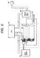
- the reference numeral 100 in Fig. 5 of the accompanying drawings designates a halogen heater, and a CPU 101 ON/OFF-controls electric power supplied from a power source outlet by a heater driver 104 having a switch on the basis of a temperature detected by a thermistor 103 for detecting the temperature of a fixing roller 105.
- the reference numeral 106 denotes a thermoswitch for preventing the excessive temperature rise of the halogen lamp
- the reference numeral 107 designates a motor driver for driving the fixing roller.
- the electric power from the outlet is directly supplied to the halogen lamp.
- the heat generating amount of the halogen lamp per unit time is determined by only the ratio between the ON time and the OFF time of the switch 104 provided in an electric power supply line, and maximum suppliable electric power is constant when the ON time is 100%.
- the present invention has been made in view of the above-noted problem and an object thereof is to provide an image forming apparatus which fully makes the most of the capability of the apparatus.
- Another object of the present invention is to provide an image forming apparatus which can carry out the maximum printing process within the range of a predetermined power consumption amount.
- Still another object of the present invention is to provide an image forming apparatus designed such that if there is electric power not used in the apparatus, the electric power can be used as much as possible by a fixing device.
- Yet still another object of the present invention is to provide an image forming apparatus comprising:
- FIG. 4 schematically shows the construction of an example of an image forming apparatus using a heating device of the electromagnetic induction heating type as an image heating and fixing device 35.
- This image forming apparatus is a laser beam printer utilizing the electrophotographic process.
- the reference numeral 21 designates a rotary drum type electrophotographic photosensitive member (hereinafter referred to as the photosensitive drum) as an image bearing member.
- This photosensitive drum 21 is rotatively driven in the clockwise direction of arrow at a predetermined peripheral speed (process speed), and in the rotating process thereof, it is uniformly charged to predetermined minus dark potential V D by a primary charging device 22.
- the reference numeral 23 denotes a laser beam scanner which outputs a laser beam L modulated correspondingly to the time-serial electric digital pixel signal of desired image information inputted from a host apparatus, not shown, such as an image reading apparatus, a word processor or a computer, and the surface of the photosensitive drum 21 uniformly charged to minus by the primary charging device 22 as previously described is scanned by and exposed to the laser beam, whereby the exposed portion becomes small in its absolute potential value and assumes light potential V L , and an electrostatic latent image corresponding to the desired image information is formed on the surface of the rotary photosensitive drum 21.
- a host apparatus not shown, such as an image reading apparatus, a word processor or a computer
- the latent image is reversal-developed with powder toner (the toner adheres to the laser-exposed portion V L ) charged to minus by a developing device 24 and is visualized.
- the developing device 24 has a rotatively driven developing sleeve 24a, and the outer peripheral surface of the sleeve is coated with a thin layer of toner having minus charges and is opposed to the surface of the photosensitive drum 21, and a developing bias voltage V DC of which the absolute value is smaller than the dark potential V D of the photosensitive drum 21 and greater than the light potential V L of the photosensitive drum 21 is applied to the sleeve 24a, whereby the toner on the sleeve 24a is transferred to only the portion of the light potential V L of the photosensitive drum 21 and the latent image is visualized (reversal-developed).
- recording materials P stacked and set on a sheet feeding tray 25 are fed one by one by a sheet feeding roller 26 and are conveyed via a conveying guide 27, a pair of registration rollers 28 and a pre-transfer guide 29 to the nip portion (transfer portion) 32 between the photosensitive drum 21 and a transfer roller 30 as a transfer member bearing against the photosensitive drum 21 and having a transfer bias applied thereto by a power source 31, at appropriate timing synchronized with the rotation of the photosensitive drum 21, and the toner image on the surface of the photosensitive drum 21 is sequentially transferred to the thus fed recording material P.
- the resistance value of the transfer roller 30 as the transfer member may suitably be of the order of 10 8 to 10 9 ⁇ m.
- the recording material P which has passed through the transfer portion 32 is separated from the surface of the photosensitive drum 21 and is introduced to a fixing device 35 by a conveying guide 34, whereby the recording material P has the transferred toner image thereon fixed, and is outputted as an image forming article (print) to a sheet discharge tray 36.
- the surface of the photosensitive drum 21 has any residual substance thereon such as untransferred toner removed by a cleaning device 33 and is cleaned and is repetitively used for image formation.
- Fig. 1 is a typical cross-sectional view of the fixing means of the image forming apparatus of the present invention.
- a fixing roller 1 is an iron mandrel cylinder having an outer diameter of 32 [mm] and a thickness of 0.5 [mm], and may be provided with a layer of PTFE 10 to 50 [ ⁇ m] or PFA 10 to 50 [ ⁇ m] in order to enhance the releasing property of the surface thereof.
- a magnetic material such as magnetic stainless steel having relatively high magnetic permeability ⁇ and suitable resistivity ⁇ .
- a pressing roller 2 has an Si rubber layer having a thickness of 5 [mm] on the outer periphery of an iron mandrel having an outer diameter of 20 [mm], and like the fixing roller 1, it may be provided with a layer of PTFE 10 to 100 [ ⁇ m] or PFA 10 to 100 [ ⁇ m] in order to enhance the releasing property of the surface thereof, and the total outer diameter thereof is about 30 [mm].
- the fixing roller 1 and the pressing roller 2 are rotatably supported, and only the fixing roller 1 is driven.
- the pressing roller 2 is in pressure contact with the surface of the fixing roller 1, and is disposed so as to be driven and rotated by the frictional force in the pressure contact portion (nip portion). Also, the pressing roller 2 is pressed in the direction of the rotary shaft of the fixing roller 1 by a mechanism, not shown, using a spring or the like.
- the pressing roller 2 is loaded with about 20 [kg], and in that case, the width of the pressure contact portion (nip width) is about 4 [mm]. In some cases, however, the load may be varied to thereby change the nip width.
- a conveying guide 3 is disposed at a location for guiding a sheet material 5 conveyed while bearing an unfixed toner image 4 thereon to the nip portion between the fixing roller 1 and the pressing roller 2.
- a separation claw 6 is disposed so as to abut against the surface of the fixing roller 1, and is for forcibly separating the sheet material 5 to thereby prevent jam when the sheet material 5 sticks on the fixing roller 1 after it has passed through the nip portion.
- An exciting coil 7 comprises 20 to 150 insulatively covered conductors having an outer diameter of 0.15 to 0.50 [mm] made into a litz, and is connected to a high frequency converter, not shown, and an alternating current of 10 to 100 [kHz] is applied thereto, and electric power up to the order of 1500 [W] is supplied thereto.
- a heat resisting material is used as the insulative covering.
- a magnetic field induced by the alternating current flowing to the exciting coil 7 flows an eddy current to the vicinity of the inner surface of the fixing roller which is electrically conductive to thereby generate Joule heat.
- a magnetic material core 8 may preferably be of high magnetic permeability and low loss, and is used to increase the efficiency of a magnetic circuit and to intercept magnetism.
- the exciting coil 7 and the magnetic material core 8 are held on the longitudinally opposite end portions of the fixing roller by a holder 9 made of aluminum, and are covered with an insulative heat-shrinkable tube 10 and are made into an exciting coil and magnetic material core unit.
- the exciting coil and magnetic core unit is inclinedly disposed as shown in Fig. 1 to efficiently supply heat to the toner image 4 and the sheet material 5 by disposing the heat generating portion immediately before the nip portion because the electrically conductive layer of the fixing roller to which the exciting coil 7 is opposed locally generates heat.
- a temperature sensor 11 is disposed so as to abut against the surface of that portion of the fixing roller 1 which locally generates heat, and the supply of electric power to the exciting coil 7 is increased or decreased on the basis of the detection signal of the temperature sensor 11, whereby the surface temperature of the fixing roller 1 is automatically controlled so as to become a predetermined constant temperature.
- Fig. 6 shows the power supply circuit and temperature control circuit of the fixing device in the present embodiment.
- a high frequency current supplied to the coil 7 by the power supply is adjusted by switching TR1 in the power supply in conformity with the detected temperature by the thermistor 11.
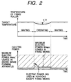
- Electric power adjusting means for adjusting the supply of electric power to the fixing means will now be described with reference to Fig. 2.
- Electric power W(t) used in portions except the fixing means is detected by electric power detecting means, and the preset maximum electric power W MAX usable by the entire image forming apparatus, minus the electric power W(t) used in the portions except the fixing means is defined as the maximum electric power W FMAX usable in the fixing means.
- the electric power detecting means detects the electric power W(t) used in the portions except the fixing means, and on the basis of the result of this detection, the electric power adjusting means adjusts the maximum electric power W MAX preset for the entire image forming apparatus, minus the electric power W(t), and supplies it to the fixing means as the maximum electric power W FMAX usable in the fixing means.
- the remaining electric power used in the portions except the fixing means can be used as the maximum electric power W FMAX usable by the fixing means and therefore, the bad fixing by the temperature drop of the fixing roller caused as by the deficiency of the electric power supplied to the fixing means can be prevented.
- the electric power adjusting means adjusts the remaining electric power being used in the portions except the fixing means and supplies it to the fixing means, whereby relative to the temperature drop 20°C when as shown in Fig. 3, the electric power usable in the fixing means is constant, the temperature drop becomes 5°C as shown in Fig. 2.
- the maximum electric power W FMAX usable in the fixing means is not adjusted only during the image forming operation, but may be adjustable also during the starting of the image forming apparatus, and in such case, the starting time of the image forming apparatus can be shortened by about 20%.
- the electric power-heat conversion efficiency is substantially constant even if the input electric power is varied, and it never happens that as in the fixing means having a halogen lamp as a heating source, the electric power-heat conversion efficiency is greatly varied when the input electric power is varied.
- the present invention relates to an image forming apparatus which has image forming means for forming an image on a recording material, image fixing means, for fixing the image onto the recording material, having an electric conductor, a coil for inducing an eddy current in the electric conductor, and a power supply for supplying an alternating current to the coil, and electric power adjusting means for adjusting a maximum electric power that the power supply can supply to the coil.
Landscapes
- Physics & Mathematics (AREA)
- General Physics & Mathematics (AREA)
- Electromagnetism (AREA)
- Engineering & Computer Science (AREA)
- Microelectronics & Electronic Packaging (AREA)
- Fixing For Electrophotography (AREA)
- Control Or Security For Electrophotography (AREA)
Abstract
Description
Claims (3)
- An image forming apparatus comprising:image forming means for forming an image on a recording material;image fixing means for fixing the image onto the recording material, said image fixing means including an electric conductor, a coil for inducing an eddy current in said electric conductor, and a power supply for supplying an alternating current to said coil; andelectric power adjusting means for adjusting a maximum electric power said power supply can supply to said coil.
- An image forming apparatus according to Claim 1, wherein said electric power adjusting means adjusts so that said power supply can supply an electric power which is made by subtracting an electric power being used in the other portions than said image fixing means from maximum electric power usable by the entire apparatus.
- An image forming apparatus according to Claim 1, further comprising electric power detecting means for detecting the electric power used in the other portions than said image fixing means, wherein said electric power adjusting means adjusts the maximum electric power said power supply can supply in conformity with the output of said electric power detecting means.
Applications Claiming Priority (2)
| Application Number | Priority Date | Filing Date | Title |
|---|---|---|---|
| JP11013885A JP2000214709A (en) | 1999-01-22 | 1999-01-22 | Image forming device |
| JP1388599 | 1999-01-22 |
Publications (3)
| Publication Number | Publication Date |
|---|---|
| EP1022623A2 true EP1022623A2 (en) | 2000-07-26 |
| EP1022623A3 EP1022623A3 (en) | 2001-09-05 |
| EP1022623B1 EP1022623B1 (en) | 2006-08-23 |
Family
ID=11845670
Family Applications (1)
| Application Number | Title | Priority Date | Filing Date |
|---|---|---|---|
| EP00101192A Expired - Lifetime EP1022623B1 (en) | 1999-01-22 | 2000-01-21 | Power regulation for induction-type heat-fixing means depending on consumption of other parts of an image forming apparatus |
Country Status (4)
| Country | Link |
|---|---|
| US (1) | US6278852B1 (en) |
| EP (1) | EP1022623B1 (en) |
| JP (1) | JP2000214709A (en) |
| DE (1) | DE60030182T2 (en) |
Cited By (4)
| Publication number | Priority date | Publication date | Assignee | Title |
|---|---|---|---|---|
| EP1617303A3 (en) * | 2004-07-15 | 2006-06-28 | Konica Minolta Business Technologies, Inc. | Image forming apparatus |
| US7289745B2 (en) | 2004-04-20 | 2007-10-30 | Konica Minolta Business Technologies, Inc. | Image forming apparatus with power supply system |
| CN100525550C (en) * | 2000-08-11 | 2009-08-05 | 佳能株式会社 | Image heating apparatus of induction heating type |
| CN103135411A (en) * | 2011-11-30 | 2013-06-05 | 株式会社理光 | Developing apparatus, image forming apparatus and process cartridge |
Families Citing this family (12)
| Publication number | Priority date | Publication date | Assignee | Title |
|---|---|---|---|---|
| JP4271790B2 (en) * | 1999-09-22 | 2009-06-03 | 東芝テック株式会社 | Fixing device |
| JP3605595B2 (en) * | 1999-12-28 | 2004-12-22 | 東芝テック株式会社 | Image forming apparatus and fixing device |
| WO2001048560A1 (en) * | 1999-12-28 | 2001-07-05 | Toshiba Tec Kabushiki Kaisha | Image forming device and fixing device |
| JP4685235B2 (en) * | 2000-12-06 | 2011-05-18 | 東芝テック株式会社 | Image forming apparatus |
| JP2002222017A (en) * | 2001-01-24 | 2002-08-09 | Canon Inc | Temperature control device |
| JP3902937B2 (en) * | 2001-10-23 | 2007-04-11 | キヤノン株式会社 | Image heating device |
| JP2005049563A (en) * | 2003-07-31 | 2005-02-24 | Canon Inc | Fixing device and image forming apparatus having the same |
| JP4262140B2 (en) | 2004-06-07 | 2009-05-13 | キヤノン株式会社 | Image forming apparatus |
| JP4617135B2 (en) * | 2004-10-25 | 2011-01-19 | キヤノン株式会社 | Image forming apparatus |
| JP4595678B2 (en) * | 2005-05-27 | 2010-12-08 | コニカミノルタビジネステクノロジーズ株式会社 | Image forming apparatus |
| US7205513B2 (en) * | 2005-06-27 | 2007-04-17 | Xerox Corporation | Induction heated fuser and fixing members |
| US7580649B2 (en) * | 2007-04-17 | 2009-08-25 | Kabushiki Kaisha Toshiba | Fixing device for image forming apparatus and control method thereof |
Family Cites Families (6)
| Publication number | Priority date | Publication date | Assignee | Title |
|---|---|---|---|---|
| JPH0242455A (en) * | 1988-08-02 | 1990-02-13 | Ricoh Co Ltd | Control method for copying machines, etc. |
| US5079409A (en) * | 1989-09-27 | 1992-01-07 | Mita Industrial Co., Ltd. | Heater control system |
| JP3338743B2 (en) * | 1995-10-19 | 2002-10-28 | 株式会社リコー | Electrophotographic equipment |
| US6006051A (en) * | 1995-10-19 | 1999-12-21 | Ricoh Company, Ltd. | Electrophotographic apparatus and image forming apparatus employed therein with controlled timing of a power supply |
| JP3376785B2 (en) * | 1995-12-01 | 2003-02-10 | ミノルタ株式会社 | Induction heating fixing device |
| JPH10301442A (en) * | 1997-04-23 | 1998-11-13 | Canon Inc | Heating device, fixing device, and image forming device |
-
1999
- 1999-01-22 JP JP11013885A patent/JP2000214709A/en active Pending
-
2000
- 2000-01-19 US US09/487,606 patent/US6278852B1/en not_active Expired - Lifetime
- 2000-01-21 EP EP00101192A patent/EP1022623B1/en not_active Expired - Lifetime
- 2000-01-21 DE DE60030182T patent/DE60030182T2/en not_active Expired - Fee Related
Cited By (5)
| Publication number | Priority date | Publication date | Assignee | Title |
|---|---|---|---|---|
| CN100525550C (en) * | 2000-08-11 | 2009-08-05 | 佳能株式会社 | Image heating apparatus of induction heating type |
| US7289745B2 (en) | 2004-04-20 | 2007-10-30 | Konica Minolta Business Technologies, Inc. | Image forming apparatus with power supply system |
| EP1617303A3 (en) * | 2004-07-15 | 2006-06-28 | Konica Minolta Business Technologies, Inc. | Image forming apparatus |
| CN103135411A (en) * | 2011-11-30 | 2013-06-05 | 株式会社理光 | Developing apparatus, image forming apparatus and process cartridge |
| CN103135411B (en) * | 2011-11-30 | 2015-03-25 | 株式会社理光 | Developing apparatus, image forming apparatus and process cartridge |
Also Published As
| Publication number | Publication date |
|---|---|
| EP1022623B1 (en) | 2006-08-23 |
| US6278852B1 (en) | 2001-08-21 |
| DE60030182T2 (en) | 2007-07-12 |
| DE60030182D1 (en) | 2006-10-05 |
| JP2000214709A (en) | 2000-08-04 |
| EP1022623A3 (en) | 2001-09-05 |
Similar Documents
| Publication | Publication Date | Title |
|---|---|---|
| US6278852B1 (en) | Image forming apparatus having electric power adjusting means | |
| US6320168B1 (en) | Induction-heating fusion device | |
| US7228084B2 (en) | Image forming apparatus and fixing device | |
| KR100886280B1 (en) | Burn heating device | |
| JPH07295414A (en) | Fixing device of image formation device | |
| EP0984339A2 (en) | Image heating apparatus and heater | |
| JP2002033182A (en) | Heating device and image forming device | |
| US7203443B2 (en) | Fixing unit which heats heating member with induction heating, and image forming apparatus which includes the fixing unit | |
| US6349187B2 (en) | Image forming apparatus | |
| US7208708B2 (en) | Image heating apparatus having first and second electroconductive layers having different resistance characteristics | |
| JP4332274B2 (en) | Image forming apparatus | |
| US6909861B2 (en) | Rotation control and heating control for a fixing rotatable member in rotational induction-heating type apparatus | |
| US7162168B2 (en) | Fixing apparatus | |
| JP3976837B2 (en) | Image heating device | |
| US6834168B2 (en) | Image fixing device having temperature detection Interval changing device | |
| JP2001126856A (en) | Induction heating device and image forming device | |
| JP4419597B2 (en) | Image forming apparatus | |
| JPH11190949A (en) | Image heating device and image forming device | |
| JP2002352943A (en) | Heating device and image forming device | |
| KR100315634B1 (en) | Apparatus for fusing of laser beam printer | |
| JP2022067934A (en) | Image forming device | |
| JP2003347031A (en) | Heating device and image forming device | |
| JP2003036960A (en) | Heating device and image forming device | |
| JP2006084648A (en) | Image forming apparatus | |
| JP2000215975A (en) | Excitation coil, fixing device, and image forming device |
Legal Events
| Date | Code | Title | Description |
|---|---|---|---|
| PUAI | Public reference made under article 153(3) epc to a published international application that has entered the european phase |
Free format text: ORIGINAL CODE: 0009012 |
|
| AK | Designated contracting states |
Kind code of ref document: A2 Designated state(s): AT BE CH CY DE DK ES FI FR GB GR IE IT LI LU MC NL PT SE |
|
| AX | Request for extension of the european patent |
Free format text: AL;LT;LV;MK;RO;SI |
|
| PUAL | Search report despatched |
Free format text: ORIGINAL CODE: 0009013 |
|
| AK | Designated contracting states |
Kind code of ref document: A3 Designated state(s): AT BE CH CY DE DK ES FI FR GB GR IE IT LI LU MC NL PT SE |
|
| AX | Request for extension of the european patent |
Free format text: AL;LT;LV;MK;RO;SI |
|
| 17P | Request for examination filed |
Effective date: 20020205 |
|
| AKX | Designation fees paid |
Free format text: DE FR GB IT |
|
| 17Q | First examination report despatched |
Effective date: 20031219 |
|
| GRAP | Despatch of communication of intention to grant a patent |
Free format text: ORIGINAL CODE: EPIDOSNIGR1 |
|
| RTI1 | Title (correction) |
Free format text: POWER REGULATION FOR INDUCTION-TYPE HEAT-FIXING MEANS DEPENDING ON CONSUMPTION OF OTHER PARTS OF AN IMAGE FORMING APPARATUS |
|
| GRAS | Grant fee paid |
Free format text: ORIGINAL CODE: EPIDOSNIGR3 |
|
| GRAA | (expected) grant |
Free format text: ORIGINAL CODE: 0009210 |
|
| AK | Designated contracting states |
Kind code of ref document: B1 Designated state(s): DE FR GB IT |
|
| PG25 | Lapsed in a contracting state [announced via postgrant information from national office to epo] |
Ref country code: IT Free format text: LAPSE BECAUSE OF FAILURE TO SUBMIT A TRANSLATION OF THE DESCRIPTION OR TO PAY THE FEE WITHIN THE PRESCRIBED TIME-LIMIT;WARNING: LAPSES OF ITALIAN PATENTS WITH EFFECTIVE DATE BEFORE 2007 MAY HAVE OCCURRED AT ANY TIME BEFORE 2007. THE CORRECT EFFECTIVE DATE MAY BE DIFFERENT FROM THE ONE RECORDED. Effective date: 20060823 |
|
| REG | Reference to a national code |
Ref country code: GB Ref legal event code: FG4D |
|
| REF | Corresponds to: |
Ref document number: 60030182 Country of ref document: DE Date of ref document: 20061005 Kind code of ref document: P |
|
| EN | Fr: translation not filed | ||
| PLBE | No opposition filed within time limit |
Free format text: ORIGINAL CODE: 0009261 |
|
| STAA | Information on the status of an ep patent application or granted ep patent |
Free format text: STATUS: NO OPPOSITION FILED WITHIN TIME LIMIT |
|
| 26N | No opposition filed |
Effective date: 20070524 |
|
| GBPC | Gb: european patent ceased through non-payment of renewal fee |
Effective date: 20070121 |
|
| PG25 | Lapsed in a contracting state [announced via postgrant information from national office to epo] |
Ref country code: GB Free format text: LAPSE BECAUSE OF NON-PAYMENT OF DUE FEES Effective date: 20070121 |
|
| PG25 | Lapsed in a contracting state [announced via postgrant information from national office to epo] |
Ref country code: FR Free format text: LAPSE BECAUSE OF FAILURE TO SUBMIT A TRANSLATION OF THE DESCRIPTION OR TO PAY THE FEE WITHIN THE PRESCRIBED TIME-LIMIT Effective date: 20070511 |
|
| PG25 | Lapsed in a contracting state [announced via postgrant information from national office to epo] |
Ref country code: FR Free format text: LAPSE BECAUSE OF FAILURE TO SUBMIT A TRANSLATION OF THE DESCRIPTION OR TO PAY THE FEE WITHIN THE PRESCRIBED TIME-LIMIT Effective date: 20060823 |
|
| PGFP | Annual fee paid to national office [announced via postgrant information from national office to epo] |
Ref country code: DE Payment date: 20090131 Year of fee payment: 10 |
|
| PG25 | Lapsed in a contracting state [announced via postgrant information from national office to epo] |
Ref country code: DE Free format text: LAPSE BECAUSE OF NON-PAYMENT OF DUE FEES Effective date: 20100803 |