EP1022492B1 - Electric shift control assembly - Google Patents
Electric shift control assembly Download PDFInfo
- Publication number
- EP1022492B1 EP1022492B1 EP99309808A EP99309808A EP1022492B1 EP 1022492 B1 EP1022492 B1 EP 1022492B1 EP 99309808 A EP99309808 A EP 99309808A EP 99309808 A EP99309808 A EP 99309808A EP 1022492 B1 EP1022492 B1 EP 1022492B1
- Authority
- EP
- European Patent Office
- Prior art keywords
- shift
- control assembly
- shift control
- assembly according
- assembly
- Prior art date
- Legal status (The legal status is an assumption and is not a legal conclusion. Google has not performed a legal analysis and makes no representation as to the accuracy of the status listed.)
- Expired - Lifetime
Links
Images


Classifications
-
- F—MECHANICAL ENGINEERING; LIGHTING; HEATING; WEAPONS; BLASTING
- F16—ENGINEERING ELEMENTS AND UNITS; GENERAL MEASURES FOR PRODUCING AND MAINTAINING EFFECTIVE FUNCTIONING OF MACHINES OR INSTALLATIONS; THERMAL INSULATION IN GENERAL
- F16H—GEARING
- F16H59/00—Control inputs to control units of change-speed- or reversing-gearings for conveying rotary motion
- F16H59/02—Selector apparatus
-
- F—MECHANICAL ENGINEERING; LIGHTING; HEATING; WEAPONS; BLASTING
- F16—ENGINEERING ELEMENTS AND UNITS; GENERAL MEASURES FOR PRODUCING AND MAINTAINING EFFECTIVE FUNCTIONING OF MACHINES OR INSTALLATIONS; THERMAL INSULATION IN GENERAL
- F16H—GEARING
- F16H63/00—Control outputs from the control unit to change-speed- or reversing-gearings for conveying rotary motion or to other devices than the final output mechanism
- F16H63/02—Final output mechanisms therefor; Actuating means for the final output mechanisms
- F16H63/30—Constructional features of the final output mechanisms
- F16H63/304—Constructional features of the final output mechanisms the final output mechanisms comprising elements moved by electrical or magnetic force
-
- F—MECHANICAL ENGINEERING; LIGHTING; HEATING; WEAPONS; BLASTING
- F16—ENGINEERING ELEMENTS AND UNITS; GENERAL MEASURES FOR PRODUCING AND MAINTAINING EFFECTIVE FUNCTIONING OF MACHINES OR INSTALLATIONS; THERMAL INSULATION IN GENERAL
- F16H—GEARING
- F16H59/00—Control inputs to control units of change-speed- or reversing-gearings for conveying rotary motion
- F16H59/68—Inputs being a function of gearing status
- F16H2059/6807—Status of gear-change operation, e.g. clutch fully engaged
-
- F—MECHANICAL ENGINEERING; LIGHTING; HEATING; WEAPONS; BLASTING
- F16—ENGINEERING ELEMENTS AND UNITS; GENERAL MEASURES FOR PRODUCING AND MAINTAINING EFFECTIVE FUNCTIONING OF MACHINES OR INSTALLATIONS; THERMAL INSULATION IN GENERAL
- F16H—GEARING
- F16H63/00—Control outputs from the control unit to change-speed- or reversing-gearings for conveying rotary motion or to other devices than the final output mechanism
- F16H63/02—Final output mechanisms therefor; Actuating means for the final output mechanisms
- F16H63/30—Constructional features of the final output mechanisms
- F16H63/304—Constructional features of the final output mechanisms the final output mechanisms comprising elements moved by electrical or magnetic force
- F16H2063/3056—Constructional features of the final output mechanisms the final output mechanisms comprising elements moved by electrical or magnetic force using cam or crank gearing
-
- F—MECHANICAL ENGINEERING; LIGHTING; HEATING; WEAPONS; BLASTING
- F16—ENGINEERING ELEMENTS AND UNITS; GENERAL MEASURES FOR PRODUCING AND MAINTAINING EFFECTIVE FUNCTIONING OF MACHINES OR INSTALLATIONS; THERMAL INSULATION IN GENERAL
- F16H—GEARING
- F16H63/00—Control outputs from the control unit to change-speed- or reversing-gearings for conveying rotary motion or to other devices than the final output mechanism
- F16H63/02—Final output mechanisms therefor; Actuating means for the final output mechanisms
- F16H63/08—Multiple final output mechanisms being moved by a single common final actuating mechanism
- F16H63/16—Multiple final output mechanisms being moved by a single common final actuating mechanism the final output mechanisms being successively actuated by progressive movement of the final actuating mechanism
- F16H63/18—Multiple final output mechanisms being moved by a single common final actuating mechanism the final output mechanisms being successively actuated by progressive movement of the final actuating mechanism the final actuating mechanism comprising cams
-
- Y—GENERAL TAGGING OF NEW TECHNOLOGICAL DEVELOPMENTS; GENERAL TAGGING OF CROSS-SECTIONAL TECHNOLOGIES SPANNING OVER SEVERAL SECTIONS OF THE IPC; TECHNICAL SUBJECTS COVERED BY FORMER USPC CROSS-REFERENCE ART COLLECTIONS [XRACs] AND DIGESTS
- Y10—TECHNICAL SUBJECTS COVERED BY FORMER USPC
- Y10T—TECHNICAL SUBJECTS COVERED BY FORMER US CLASSIFICATION
- Y10T74/00—Machine element or mechanism
- Y10T74/19—Gearing
- Y10T74/19219—Interchangeably locked
- Y10T74/19251—Control mechanism
- Y10T74/19279—Cam operated
-
- Y—GENERAL TAGGING OF NEW TECHNOLOGICAL DEVELOPMENTS; GENERAL TAGGING OF CROSS-SECTIONAL TECHNOLOGIES SPANNING OVER SEVERAL SECTIONS OF THE IPC; TECHNICAL SUBJECTS COVERED BY FORMER USPC CROSS-REFERENCE ART COLLECTIONS [XRACs] AND DIGESTS
- Y10—TECHNICAL SUBJECTS COVERED BY FORMER USPC
- Y10T—TECHNICAL SUBJECTS COVERED BY FORMER US CLASSIFICATION
- Y10T74/00—Machine element or mechanism
- Y10T74/19—Gearing
- Y10T74/19219—Interchangeably locked
- Y10T74/19377—Slidable keys or clutches
- Y10T74/19414—Single clutch shaft
- Y10T74/19419—Progressive
- Y10T74/19423—Multiple key
- Y10T74/19428—Spur
- Y10T74/19437—Electrically operated
-
- Y—GENERAL TAGGING OF NEW TECHNOLOGICAL DEVELOPMENTS; GENERAL TAGGING OF CROSS-SECTIONAL TECHNOLOGIES SPANNING OVER SEVERAL SECTIONS OF THE IPC; TECHNICAL SUBJECTS COVERED BY FORMER USPC CROSS-REFERENCE ART COLLECTIONS [XRACs] AND DIGESTS
- Y10—TECHNICAL SUBJECTS COVERED BY FORMER USPC
- Y10T—TECHNICAL SUBJECTS COVERED BY FORMER US CLASSIFICATION
- Y10T74/00—Machine element or mechanism
- Y10T74/19—Gearing
- Y10T74/19642—Directly cooperating gears
- Y10T74/19679—Spur
- Y10T74/19684—Motor and gearing
Definitions
- the invention relates generally to an electric shift control assembly for power transmission systems and more specifically to an electric shift control assembly for use in motor vehicle drive line components such as transfer cases and transmissions.
- Shift assemblies that is, devices which achieve selection of two or more gears or speed ranges in motor vehicle drive line components such as transmissions and transfer cases have evolved significantly over the years. Initially, such devices were exclusively manual, that is, actuated by the driver and comprised a plurality of parallel shift rails and forks which were selectively engaged and bi-directionally translated by an operator controlled shift lever.
- shift mechanism may be similar to early transmission mechanisms including, for example, a single shift rail which may be moved bi-directionally to engage high gear, low gear and neutral. Numerous other mechanical arrangements are utilized to achieve high and low gear selection.
- EP 0882 912 discloses a transfer casing, wherein the shift fork has an internal screw thread and is disposed on a threaded shift rail. The shift rail is rotatably driven by a motor to axially displace the shift fork.
- a shift fork may be slidably disposed on a fixed rail adjacent a rotatable shift rail.
- the rotatable shift rail is coupled to an energy storage device such as a spring which drives a cam engaged by a follower on the shift fork.
- the energy storage device stores energy so that shifts that cannot be immediately completed due to gear clash will be completed upon engageable alignment of gear teeth.
- a device of this type is disclosed in US 5,150,637 in connection with a differential gear clutch.
- Other assemblies utilizing, for example, rotating sector plates or ball screw actuators provides bi-directional motion to achieve such gear and speed selection.
- the present invention provides a transfer case shift control assembly for selecting one of a plurality of operating modes comprising, in combination, an input member, a speed reduction assembly having an output, a clutch member for selectively engaging at least said input member and said speed reduction assembly output, a shift fork engaging said clutch member, said shift fork disposed on a rotatable shift rail which is driveable by means of an electric drive motor having an output characterised in that the shift rail has a pair of spaced apart cam followers, and the shift fork includes a pair of cams, each of said cams engaged by a respective one of said pair of cam followers, a plate being disposed for rotation with said shift rail, said plate defining an array of spaced-apart apertures, a plurality of sensors being disposed in sensing relationship with said array of apertures, and a gear train is provided to be driven by the output of the drive motor to drive said shift rail.
- the cams may comprise helical cam surfaces engaged by the cam followers.
- the shift rail can rotate bi-directionally, so the shift fork assembly and clutch collar can be bi-directionally translated.
- the plate which rotates with the shift rail can be circular. As the circular plate and shift rail rotate, the sensors can generate unique combinations of signals corresponding to a plurality of specific angular positions of the shift rail and translational positions of the shift fork.
- the four-wheel vehicle drive train 10 includes a prime mover 12 which is coupled to and directly drives a transmission 14.
- the transmission 14 may either be an automatic or manual type.
- the output of the transmission 14 directly drives a transfer case assembly 16 which provides motive power to a primary or rear drive line 20 comprising a primary or rear prop shaft 22, a primary or rear differential 24, a pair of live primary or rear axles 26 and a respective pair of primary or rear tire and wheel assemblies 28.
- the transfer case assembly 16 also selectively provides motive power to a secondary or front drive line 30 comprising a secondary or front prop shaft 32, a secondary or front differential assembly 34, a pair of live secondary or front axles 36 and a respective pair of secondary or front tire and wheel assemblies 38.
- the front tire and wheel assemblies 38 may be directly coupled to a respective one of the pair of front axles 36 or, if desired, a pair of manually or remotely activateable locking hubs 42 may be operably disposed between the pair of front axles 36 and a respective one of the tire and wheel assemblies 38 to selectively connect same.
- both the primary drive line 20 and the secondary drive line 30 may include suitable and appropriately disposed universal joints 44 which function in conventional fashion to allow static and dynamic offsets and misalignments between the various shafts and components.
- a control console 46 which is preferably disposed within convenient reach of the vehicle operator includes a switch or a plurality of individual switches or push buttons 48 which facilitate selection of the operating mode of the transfer case assembly 16 as will be further described below.
- the rear drive line 20 functions as the primary drive line, i.e., it is engaged and operates substantially all the time and, correspondingly, the front drive line 30 functions as the secondary drive line, i.e., it is engaged and operates only part-time or in a secondary or supplemental fashion, such a vehicle commonly being referred to as a rear wheel drive vehicle.
- the transfer case assembly 16 includes a multiple piece, typically cast, housing assembly 50 having planar and circular sealing surfaces, openings for shafts and bearings and various recesses, shoulders, flanges, counterbores and the like to receive various components and assemblies of the transfer case assembly 16.
- An input shaft 52 includes female or internal splines or gear teeth 54 or other suitable structure which drivingly couple an output of the transmission 14 illustrated in Figure 1 to the input shaft 52.
- the input shaft 52 is rotatably supported externally by an anti-friction bearing such as the ball bearing assembly 56 and internally by an anti-friction bearing such as the roller bearing assembly 58.
- the roller bearing assembly 58 is disposed upon a reduced diameter portion of an output shaft 60.
- An oil seal 62 positioned between the input shaft 52 and the housing assembly 50, provides an appropriate fluid tight seal therebetween.
- the opposite end of the output shaft 60 is supported by an anti-friction bearing such as a ball bearing assembly 64.
- An end cap or seal 66 closes off the end of an axial passageway 68 in the output shaft 60.
- a gerotor pump P will typically be utilized to provide a flow of lubricating and cooling fluid to the axial passageway 68 which is thence distributed through a plurality of radial ports in the output shaft 60 to the components of the transfer case assembly 16.
- the transfer case assembly 16 also includes a two-speed planetary (epicyclic) gear assembly 70 disposed generally about the input shaft 52.
- the planetary gear assembly 70 includes a sun gear collar 72 having a plurality of external gear teeth 74 and a plurality of internal splines or gear teeth 76.
- the internal splines or gear teeth 76 are engaged by complementary external splines or gear teeth 78 formed on the input shaft 52.
- Radially aligned with the sun gear 72 and its teeth 74 is a ring gear 80 having internal gear teeth 82.
- the ring gear 80 is fixedly retained within the housing assembly 50 by any suitable retaining structure such as a projection or lip 84 formed in the housing assembly 50 and a cooperating snap ring 86.
- a plurality of pinion gears 88 are rotatably received upon a like plurality of anti-friction bearings such as roller bearings 90 which, in turn, are supported and located by a like plurality of stub shafts 92.
- the plurality of stub shafts 92 are mounted within and secured to a planet carrier 94.
- the planet carrier 94 includes a plurality of internal splines or gear teeth 96.
- the planetary gear assembly 70 is more fully described in co-owned U. S. Patent No. 4,440,042.
- the planetary gear assembly 70 also includes a dog clutch or clutch collar 100 defining elongate internal splines or gear teeth 102.
- the internal splines or gear teeth 102 of the clutch collar 100 are slidably received upon a complementary plurality of external splines or gear teeth 104 on the output shaft 60.
- the clutch collar 100 thus rotates with the output shaft 60 but may translate bi-directionally therealong.
- the clutch collar 100 also includes external splines or gear teeth 106 on one end which are in all respects complementary to the internal splines or gear teeth 96 on the planet carrier 94.
- the end of the clutch collar 100 opposite the gear teeth 96 defines a circumferentially and radially extending flange 108.
- the clutch collar 100 is capable of three positions and operational modes. In the lower portion of Figure 2, the clutch collar 100 is illustrated in its leftmost or direct drive position. Direct drive is achieved when the internal splines or gear teeth 102 of the clutch collar 100 engage the external splines or gear teeth 78 on the input shaft 52 thereby directly coupling the input shaft 52 to the output shaft 60 and providing direct or high gear drive therebetween.
- the speed reduction achieved by the planetary gear assembly 70 is engaged through engagement of the external splines or gear teeth 106 on the clutch collar 100 with the internal splines or gear teeth 96 on the planet carrier 94. So engaged, the planetary gear assembly 70 is active and provides a speed reduction, typically in the range of from 3:1 to 4:1 between the input shaft 52 and the output shaft 60. Between these two positions is a neutral position. In the center, neutral position both the input shaft 52 and the planet carrier 94 are disconnected from the output shaft 60 and no power is transmitted therebetween.
- the shift control assembly 110 includes an auxiliary, preferably plastic housing 112.
- the auxiliary housing 112 includes various openings and counterbores which receive components of the electric shift control assembly 110 and protects such components as well.
- Secured to the auxiliary housing 112 is an electric drive motor 114 having an output shaft 116 coupled to a drive pinion 118.
- the drive pinion 118 is in constant mesh with the teeth of a first spur gear 120 which is received upon a stub shaft 122 which seats within suitably disposed counterbores 124 formed in the auxiliary housing 112, as noted above.
- the first spur gear 120 is coupled to or integrally formed with a second pinion gear 126 which effects a second speed reduction with a second spur gear 128.
- the second spur gear 128 is secured to a stub shaft 130 which is received within suitable aligned counterbores 132 formed in the auxiliary housing 112.
- a third pinion gear 134 is integrally formed with or secured to the second spur gear 128 and effects a third speed reduction as it drives a third spur gear 138.
- the third spur gear 138 is fixedly secured to an output shaft assembly 140 and rotates therewith.
- the output shaft assembly 140 includes a circular disc or plate 142 secured to or integrally formed with an output shaft 144 received within a counterbore 146 and a sleeve 148 in a large through passageway 152.
- a flat, apertured plate or disc 154 having an array of curved apertures 156 disposed in tracks 158A, 158B and 158C in a configuration which is analogous to and generates Gray code data as the circular plate 142 rotates past a plurality of non-contact sensors 160A, 160B and 160C.
- the apertured disc 154 is ferrous and has magnetic characteristics to interact with the preferred Hall effect sensors 160A, 160B and 160C described below. However, it may be made of other materials which appropriately interact with the specific type of sensors 160A, 160B and 160C utilized.
- Each of the sensors 160A, 160B and 160C aligns with one of the tracks 158A, 158B and 158C of the apertures 156 in the circular plate 154.
- the sensors 160A, 160B and 160C are preferably Hall effect sensors although other types of sensors such as optical or variable reluctance sensors may be utilized.
- a circular plate 154 having two tracks and two sensors or four tracks and four sensors may also be utilized.
- the outputs of the sensors 160A, 160B and 160C are provided to output terminals 162 on a circuit board or similar insulating mounting 164 and thence to suitable electrical wires or conductors (not illustrated).
- the output shaft 144 also defines a counterbore 174 having female or internal splines 176 which receive complementarily configured male or external splines 178 on a rotatable shift rail 180.
- An oil seal 184 provides a suitable fluid-tight seal between the shift rail 180 and the housing assembly 50.
- the rotatable shift rail 180 extends across the housing assembly 50 and its opposite end is seated within a suitable counterbore 176 formed in the housing assembly 50.
- a pair of spaced-apart radially disposed stanchions or stub shafts 190 are securely seated within radial passageways,192 in the shift rail 180.
- the stub shafts 190 include enlarged heads which retain freely rotatable cam followers or rollers 194 thereon.
- Disposed between the spaced-apart stanchions or stub shafts 190 and the rollers 194 is a shift fork assembly 200.
- the shift fork assembly 200 includes a body 202 having a through passageway 204 which is sized to just freely rotatably receive the shift rail 180.
- a helical cam 206 At each end of the shift fork body 202 is a helical cam 206.
- the angle of the helical cams 206 is chosen to balance the forces that result from the drag of the automatic transmission 14 in neutral.
- the helical cams 206 are correspondingly disposed such that the axial distance from corresponding points on their surfaces is just slightly less than the distance between the inside surfaces of the rollers 194.
- An axially extending face or shoulder 208 which represents a discontinuity in the helical cams 206 acts as a positive stop in one direction of rotation as it engages one of the rollers 196.
- the shift fork assembly 200 also includes an obliquely extending web 210 which terminates in a shift yoke 212 having ears which define a discontinuous, semi-circular channel or groove 214.
- the semi-circular channel or groove 214 receives and engages the flange 108 of the clutch collar 100. Such engagement inhibits rotation of the shift fork assembly 200.
- the shift rail 180 and the cam followers or rollers 194 rotate, the shift fork assembly 200 and specifically the yoke 212 and clutch collar 100 translate axially and bi-directionally. Such translation of the yoke 212 effects selective engagement of the clutch collar 100 and selection of high gear, neutral or low gear as previously explained.
- the transfer case assembly 16 also includes an electromagnetically actuated disc pack type clutch assembly 220.
- the clutch assembly 220 is disposed about the output shaft 60 and includes a circular drive member 222 coupled to the output shaft 60 through, for example, a splined interconnection.
- the circular drive member 222 includes a plurality of circumferentially spaced-apart recesses 226 in the shape of an oblique section of a helical torus. Each of the recesses 226 receives one of a like plurality of load transferring balls 228.
- a circular driven member 232 is disposed adjacent the circular drive member 222 and includes a like plurality of opposed recesses 234 defining the same shape as the recesses 226.
- the oblique side walls of the recesses 226 and 234 function as ramps or cams and cooperate with the balls 228 to drive the circular members 222 and 232 apart in response to relative rotation therebetween.
- the recesses 226 and 234 and the load transferring balls 228 may be replaced with other analogous mechanical elements which cause axial displacement of the circular members 222 and 232 in response to relative rotation therebetween.
- tapered rollers disposed in complementarily configured conical helices may be utilized.
- the circular driven member 232 extends radially outwardly and is secured to a soft iron rotor 236.
- An armature 242 is disposed adjacent the face of the rotor 236.
- the rotor 236 surrounds an electromagnetic coil 244 on three sides.
- the electromagnetic coil 244 is provided with electrical energy preferably from a pulse width iuodulation (PWM) control through an electrical conductor 246.
- PWM pulse width iuodulation
- the pulse width modulation scheme increases or decreases the average current to the electromagnetic coil 244 of the electromagnetic clutch assembly 220 and thus torque throughput of the disc pack type clutch assembly 220, as will be more fully described below, by increasing or decreasing the on time (duty cycle) of a drive signal. It will be appreciated that other modulating control techniques may be utilized to achieve engagement and disengagement of the electromagnetic disc pack type clutch assembly 220.
- Providing electrical energy to the electromagnetic coil 244 causes magnetic attraction of the armature 242 with the rotor 236. This magnetic attraction results in frictional contact of the armature 242 to the rotor 236.
- This frictional contact results in a frictional torque being transferred from the output shaft 60, through the circular drive member 222, through the load transferring balls 228 and to the circular driven member 232.
- the resulting frictional torque causes the balls 228 to ride up the ramps of the recesses 226 and 234, causing axial displacement of the circular drive member 222.
- Axial displacement of the circular drive member 222 translates an apply plate 248 axially toward a disc pack clutch assembly 250.
- a compression spring 252 which may comprise a stack of Belleville washers provides a restoring force which biases the circular drive member 222 toward the circular driven member 232 and returns the load transferring balls 228 to center positions in the circular recesses 226 and 234 to provide maximum clearance and minimum friction between the components of the electromagnetic clutch assembly 220 when it is deactivated.
- An important design consideration of the recesses 226 and 234 and the balls 228 is that the geometry of their design and the design of the compression spring 252 and the clearances in the disc pack assembly 250 ensure that the electromagnetic clutch assembly 220 is not self-locking.
- the electromagnetic clutch assembly 220 must not self-engage but rather must be capable of controlled, proportional engagement and torque transfer in direct response to the modulating control input.
- the disc pack clutch assembly 250 includes a first plurality of smaller friction plates or discs 254.
- the first plurality of discs 254 are coupled by interengaging splines to a clutch hub 256 which is coupled to the output shaft 60 for rotation therewith.
- a second plurality of larger friction plates or discs 258 are coupled to an annular housing 260 by interengaging splines for rotation therewith and are interleaved with the first plurality of friction discs 254.
- the annular housing 260 is disposed concentrically about the output shaft 60 and is coupled to a chain drive sprocket 262 by a plurality of interengaging splines or lugs and recesses 264.
- the chain drive sprocket 262 is freely rotatably disposed on the output shaft 60 and is supported by a journal or needle bearing assembly 266.
- a drive chain 268 is received upon the chain drive sprocket 262 and engages and transfers rotational energy to a driven chain sprocket 270.
- the driven chain sprocket 270 is coupled to a front (secondary) output shaft 272 of the transfer case assembly 16 by interengaging splines 274.
- the transfer case assembly 16 also includes a first Hall effect sensor 280 having an output line 282 which is disposed in proximate, sensing relationship with a plurality of teeth on a first tone wheel 286 which is coupled to and rotates with the rear (primary) output shaft 60.
- a second Hall effect sensor 290 has an output line 292 and is disposed in proximate, sensing relationship with a plurality of teeth on a second tone wheel 296 disposed adjacent the driven sprocket 270 on the front output shaft 272.
- the number of teeth on the first tone wheel 286 is identical to the number of teeth on the second tone wheel 296 so that identical shaft speeds result in the same number of pulses per unit time from the Hall effect sensors 280 and 290.
- the first and second Hall effect sensors 280 and 290 sense the respective adjacent teeth and provide a series of pulses in the lines 282 and 292, respectively, which may be utilized to compute the instantaneous rotational speeds of the rear output shaft 60 and the front output shaft 272 which, of course, correspond to the rotational speeds and the rear drive shaft 22 and the front drive shaft 32, respectively.
- the transfer case assembly 16 incorporating an electric shift control assembly 110 provides improved operational control and positioning of a clutch collar such as the clutch collar 100 and indication of the position of such clutch collar 100.
- a clutch collar such as the clutch collar 100
- Such improved operation is the result of several features of this assembly.
- securing the flat, apertured plate or disc 154 so that it rotates with, and is therefore always representative of the position of the shift rail 180 and thus of the shift fork assembly 200 ensures that any controller or microprocessor receives accurate information regarding the position of these components.
- the non-contact Hall effect sensors 160A, 160B and 160C provide both high definition of the position of the shift fork assembly 200 as well as improved reliability.
Landscapes
- Engineering & Computer Science (AREA)
- General Engineering & Computer Science (AREA)
- Mechanical Engineering (AREA)
- Gear-Shifting Mechanisms (AREA)
Description
- The invention relates generally to an electric shift control assembly for power transmission systems and more specifically to an electric shift control assembly for use in motor vehicle drive line components such as transfer cases and transmissions.
- Shift assemblies, that is, devices which achieve selection of two or more gears or speed ranges in motor vehicle drive line components such as transmissions and transfer cases have evolved significantly over the years. Initially, such devices were exclusively manual, that is, actuated by the driver and comprised a plurality of parallel shift rails and forks which were selectively engaged and bi-directionally translated by an operator controlled shift lever.
- With the advent of automatic transmissions, the shift lever became a mode selection device rather than a speed range selection device, the actual gear shifting occurring within the transmission, and generally without significant operator input.
- Similarly, manual control of transfer case speed ranges has undergone an evolution from direct, manual control to selection by an electric, hydraulic or pneumatic operator controlled by direct driver input or a microprocessor. With direct, manual control, the shift mechanism may be similar to early transmission mechanisms including, for example, a single shift rail which may be moved bi-directionally to engage high gear, low gear and neutral. Numerous other mechanical arrangements are utilized to achieve high and low gear selection. One example is given by EP 0882 912 which discloses a transfer casing, wherein the shift fork has an internal screw thread and is disposed on a threaded shift rail. The shift rail is rotatably driven by a motor to axially displace the shift fork. The position of the shift fork is sensed with a sensor located adjacent the shift fork and operable to sense axial motion of the fork. As mentioned below, such arrangements are not always practicable and may lead to packaging problems. Alternatively, a shift fork may be slidably disposed on a fixed rail adjacent a rotatable shift rail. The rotatable shift rail is coupled to an energy storage device such as a spring which drives a cam engaged by a follower on the shift fork. The energy storage device stores energy so that shifts that cannot be immediately completed due to gear clash will be completed upon engageable alignment of gear teeth. A device of this type is disclosed in US 5,150,637 in connection with a differential gear clutch. Other assemblies utilizing, for example, rotating sector plates or ball screw actuators provides bi-directional motion to achieve such gear and speed selection.
- When integrated with a microprocessor or other control system, it is commonly necessary to sense, in real time, the position of the shift member. Given such complex systems, it is generally advisable to detect such shift member position as proximate as possible to the actual components, i.e., the gears, achieving the shift. That is, if the assembly includes an energy storage device, it will be understood that the driving components of the mechanism may be in a position distinct from the driven components. Attempting to sense the position of the driven components from the drive components may thus readily introduce positional error. However, installing position sensors sufficiently proximate the driven or controlled element, i.e., the gears, may create significant packaging problems. Thus, gear shift operator assemblies wherein driving and driven components can be assured of always taking corresponding positions and thus permitting the position sensing to occur near the driving mechanism rather than the driven mechanism simplifies packaging and assembly issues. The present invention is directed to such an improved configuration.
- The present invention provides a transfer case shift control assembly for selecting one of a plurality of operating modes comprising, in combination,
an input member,
a speed reduction assembly having an output,
a clutch member for selectively engaging at least said input member and said speed reduction assembly output,
a shift fork engaging said clutch member, said shift fork disposed on a rotatable shift rail which is driveable by means of an electric drive motor having an output
characterised in that the shift rail has a pair of spaced apart cam followers, and the shift fork includes a pair of cams, each of said cams engaged by a respective one of said pair of cam followers,
a plate being disposed for rotation with said shift rail, said plate defining an array of spaced-apart apertures,
a plurality of sensors being disposed in sensing relationship with said array of apertures,
and a gear train is provided to be driven by the output of the drive motor to drive said shift rail. The cams may comprise helical cam surfaces engaged by the cam followers. The shift rail can rotate bi-directionally, so the shift fork assembly and clutch collar can be bi-directionally translated. The plate which rotates with the shift rail can be circular. As the circular plate and shift rail rotate, the sensors can generate unique combinations of signals corresponding to a plurality of specific angular positions of the shift rail and translational positions of the shift fork. - Thus it is an object of the present invention to provide an electric shift control assembly for a power transmission device such as a motor vehicle transmission or transfer case.
- It is a further object of the present invention to provide an electric shift control assembly having a bi-directionally rotating shift rail which engages a cam and shift fork slidably disposed thereon.
- It is a still further object of the present invention to provide an electric shift control assembly having an apertured plate secured to said rotating shift rail and a plurality of sensors disposed adjacent the apertured plate.
- It is a still further object of the present invention to provide an electric shift control assembly having an electric motor and a speed reducing gear train having a bi-directionally rotating output coupled to a rotating shift rail.
- Further objects and advantages of the present invention will become apparent by reference to the following description of an embodiment and appended drawings wherein like reference numbers refer to the same component, element or feature.
-
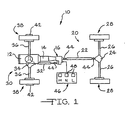
- Figure 1 is a diagrammatic, plan view of a four-wheel drive motor vehicle having a transfer case incorporating a shift control assembly according to the present invention;
- Figure 2 is full, sectional view of a transfer case incorporating a shift control assembly according to the present invention;
- Figure 3 is an enlarged, fragmentary, sectional view of a shift control drive assembly according to the present invention;
- Figure 4 is an enlarged, fragmentary, perspective view of a shift fork assembly according to the present invention; and
- Figure 5 is an enlarged, side elevational view of a position encoding device of a shift control assembly according to the present invention.
- Referring now to Figure 1, a four-wheel vehicle drive train is diagrammatically illustrated and designated by the
reference number 10. The four-wheelvehicle drive train 10 includes aprime mover 12 which is coupled to and directly drives atransmission 14. Thetransmission 14 may either be an automatic or manual type. The output of thetransmission 14 directly drives atransfer case assembly 16 which provides motive power to a primary orrear drive line 20 comprising a primary orrear prop shaft 22, a primary orrear differential 24, a pair of live primary orrear axles 26 and a respective pair of primary or rear tire andwheel assemblies 28. - The
transfer case assembly 16 also selectively provides motive power to a secondary orfront drive line 30 comprising a secondary orfront prop shaft 32, a secondary or frontdifferential assembly 34, a pair of live secondary orfront axles 36 and a respective pair of secondary or front tire andwheel assemblies 38. The front tire andwheel assemblies 38 may be directly coupled to a respective one of the pair offront axles 36 or, if desired, a pair of manually or remotelyactivateable locking hubs 42 may be operably disposed between the pair offront axles 36 and a respective one of the tire andwheel assemblies 38 to selectively connect same. Finally, both theprimary drive line 20 and thesecondary drive line 30 may include suitable and appropriately disposeduniversal joints 44 which function in conventional fashion to allow static and dynamic offsets and misalignments between the various shafts and components. Acontrol console 46 which is preferably disposed within convenient reach of the vehicle operator includes a switch or a plurality of individual switches orpush buttons 48 which facilitate selection of the operating mode of thetransfer case assembly 16 as will be further described below. - The foregoing and following description relates to a vehicle wherein the
rear drive line 20 functions as the primary drive line, i.e., it is engaged and operates substantially all the time and, correspondingly, thefront drive line 30 functions as the secondary drive line, i.e., it is engaged and operates only part-time or in a secondary or supplemental fashion, such a vehicle commonly being referred to as a rear wheel drive vehicle. - These designations "primary" and "secondary" are utilized herein rather than "front" and "rear" inasmuch as the invention herein disclosed and claimed may be readily utilized in transmissions and transfer cases wherein the
primary drive line 20 is disposed at the front of the vehicle and thesecondary drive line 30 is disposed at the rear of the vehicle. Such designations "primary" and "secondary" thus broadly and properly characterize the function of the individual drive lines rather than their specific locations. - Referring now to Figures 1 and 2, the
transfer case assembly 16 incorporating the present invention includes a multiple piece, typically cast,housing assembly 50 having planar and circular sealing surfaces, openings for shafts and bearings and various recesses, shoulders, flanges, counterbores and the like to receive various components and assemblies of thetransfer case assembly 16. An input shaft 52 includes female or internal splines orgear teeth 54 or other suitable structure which drivingly couple an output of thetransmission 14 illustrated in Figure 1 to the input shaft 52. The input shaft 52 is rotatably supported externally by an anti-friction bearing such as the ball bearingassembly 56 and internally by an anti-friction bearing such as the roller bearingassembly 58. The roller bearingassembly 58 is disposed upon a reduced diameter portion of an output shaft 60. Anoil seal 62, positioned between the input shaft 52 and thehousing assembly 50, provides an appropriate fluid tight seal therebetween. The opposite end of the output shaft 60 is supported by an anti-friction bearing such as a ball bearing assembly 64. An end cap or seal 66 closes off the end of an axial passageway 68 in the output shaft 60. A gerotor pump P will typically be utilized to provide a flow of lubricating and cooling fluid to the axial passageway 68 which is thence distributed through a plurality of radial ports in the output shaft 60 to the components of thetransfer case assembly 16. - The
transfer case assembly 16 also includes a two-speed planetary (epicyclic)gear assembly 70 disposed generally about the input shaft 52. Theplanetary gear assembly 70 includes asun gear collar 72 having a plurality ofexternal gear teeth 74 and a plurality of internal splines orgear teeth 76. The internal splines orgear teeth 76 are engaged by complementary external splines or gear teeth 78 formed on the input shaft 52. Radially aligned with thesun gear 72 and itsteeth 74 is aring gear 80 havinginternal gear teeth 82. Thering gear 80 is fixedly retained within thehousing assembly 50 by any suitable retaining structure such as a projection orlip 84 formed in thehousing assembly 50 and a cooperating snap ring 86. A plurality of pinion gears 88 are rotatably received upon a like plurality of anti-friction bearings such asroller bearings 90 which, in turn, are supported and located by a like plurality ofstub shafts 92. The plurality ofstub shafts 92 are mounted within and secured to aplanet carrier 94. Theplanet carrier 94 includes a plurality of internal splines or gear teeth 96. Theplanetary gear assembly 70 is more fully described in co-owned U. S. Patent No. 4,440,042. - The
planetary gear assembly 70 also includes a dog clutch orclutch collar 100 defining elongate internal splines orgear teeth 102. The internal splines orgear teeth 102 of theclutch collar 100 are slidably received upon a complementary plurality of external splines orgear teeth 104 on the output shaft 60. Theclutch collar 100 thus rotates with the output shaft 60 but may translate bi-directionally therealong. Theclutch collar 100 also includes external splines orgear teeth 106 on one end which are in all respects complementary to the internal splines or gear teeth 96 on theplanet carrier 94. The end of theclutch collar 100 opposite the gear teeth 96 defines a circumferentially and radially extendingflange 108. - The
clutch collar 100 is capable of three positions and operational modes. In the lower portion of Figure 2, theclutch collar 100 is illustrated in its leftmost or direct drive position. Direct drive is achieved when the internal splines orgear teeth 102 of theclutch collar 100 engage the external splines or gear teeth 78 on the input shaft 52 thereby directly coupling the input shaft 52 to the output shaft 60 and providing direct or high gear drive therebetween. - When the
clutch collar 100 is moved to the right from the position illustrated in the lower portion of Figure 2, to the position illustrated in the upper portion of Figure 2, the speed reduction achieved by theplanetary gear assembly 70 is engaged through engagement of the external splines orgear teeth 106 on theclutch collar 100 with the internal splines or gear teeth 96 on theplanet carrier 94. So engaged, theplanetary gear assembly 70 is active and provides a speed reduction, typically in the range of from 3:1 to 4:1 between the input shaft 52 and the output shaft 60. Between these two positions is a neutral position. In the center, neutral position both the input shaft 52 and theplanet carrier 94 are disconnected from the output shaft 60 and no power is transmitted therebetween. - Referring now to Figures 2 and 3, the position of the
clutch collar 100 is commanded by an electricshift control assembly 110. Theshift control assembly 110 includes an auxiliary, preferablyplastic housing 112. Theauxiliary housing 112 includes various openings and counterbores which receive components of the electricshift control assembly 110 and protects such components as well. Secured to theauxiliary housing 112 is anelectric drive motor 114 having an output shaft 116 coupled to adrive pinion 118. Thedrive pinion 118 is in constant mesh with the teeth of afirst spur gear 120 which is received upon astub shaft 122 which seats within suitablydisposed counterbores 124 formed in theauxiliary housing 112, as noted above. Thefirst spur gear 120 is coupled to or integrally formed with asecond pinion gear 126 which effects a second speed reduction with asecond spur gear 128. Similarly, thesecond spur gear 128 is secured to a stub shaft 130 which is received within suitable alignedcounterbores 132 formed in theauxiliary housing 112. Athird pinion gear 134 is integrally formed with or secured to thesecond spur gear 128 and effects a third speed reduction as it drives athird spur gear 138. Thethird spur gear 138 is fixedly secured to anoutput shaft assembly 140 and rotates therewith. Theoutput shaft assembly 140 includes a circular disc orplate 142 secured to or integrally formed with anoutput shaft 144 received within acounterbore 146 and asleeve 148 in a large throughpassageway 152. - Referring now to Figures 3 and 5, secured to the
circular plate 142 by any suitable means such as rivets is a flat, apertured plate ordisc 154 having an array ofcurved apertures 156 disposed intracks circular plate 142 rotates past a plurality ofnon-contact sensors apertured disc 154 is ferrous and has magnetic characteristics to interact with the preferredHall effect sensors sensors sensors tracks apertures 156 in thecircular plate 154. Thesensors - As is apparent from Figure 5, and the following Truth Table, Table I, incremental rotation of the
circular plate 154 provides a plurality of unique combinations of signals from thesensors TABLE I Position SENSOR H I1 I2 N I3 I4 L 160A 1 1 1 1 0 0 0 160B 1 1 0 0 1 1 0 160C 1 0 1 0 1 0 1 - Depending upon the definition necessary, that is, how many unique detected and coded positions of the
circular plate 154 are necessary as well as the logic and operating capabilities of the microprocessor and its software, acircular plate 154 having two tracks and two sensors or four tracks and four sensors may also be utilized. The outputs of thesensors output terminals 162 on a circuit board or similar insulating mounting 164 and thence to suitable electrical wires or conductors (not illustrated). - The
output shaft 144 also defines acounterbore 174 having female orinternal splines 176 which receive complementarily configured male orexternal splines 178 on arotatable shift rail 180. Anoil seal 184 provides a suitable fluid-tight seal between theshift rail 180 and thehousing assembly 50. - Referring now to Figures 2 and 4, the
rotatable shift rail 180 extends across thehousing assembly 50 and its opposite end is seated within asuitable counterbore 176 formed in thehousing assembly 50. A pair of spaced-apart radially disposed stanchions orstub shafts 190 are securely seated within radial passageways,192 in theshift rail 180. Thestub shafts 190 include enlarged heads which retain freely rotatable cam followers orrollers 194 thereon. Disposed between the spaced-apart stanchions orstub shafts 190 and therollers 194 is ashift fork assembly 200. Theshift fork assembly 200 includes abody 202 having a throughpassageway 204 which is sized to just freely rotatably receive theshift rail 180. At each end of theshift fork body 202 is ahelical cam 206. Preferably, the angle of thehelical cams 206 is chosen to balance the forces that result from the drag of theautomatic transmission 14 in neutral. Thehelical cams 206 are correspondingly disposed such that the axial distance from corresponding points on their surfaces is just slightly less than the distance between the inside surfaces of therollers 194. An axially extending face orshoulder 208 which represents a discontinuity in thehelical cams 206 acts as a positive stop in one direction of rotation as it engages one of therollers 196. - The
shift fork assembly 200 also includes an obliquely extendingweb 210 which terminates in ashift yoke 212 having ears which define a discontinuous, semi-circular channel orgroove 214. The semi-circular channel or groove 214 receives and engages theflange 108 of theclutch collar 100. Such engagement inhibits rotation of theshift fork assembly 200. Accordingly, as theshift rail 180 and the cam followers orrollers 194 rotate, theshift fork assembly 200 and specifically theyoke 212 andclutch collar 100 translate axially and bi-directionally. Such translation of theyoke 212 effects selective engagement of theclutch collar 100 and selection of high gear, neutral or low gear as previously explained. - Referring again to Figure 2, the
transfer case assembly 16 also includes an electromagnetically actuated disc pack type clutch assembly 220. The clutch assembly 220 is disposed about the output shaft 60 and includes acircular drive member 222 coupled to the output shaft 60 through, for example, a splined interconnection. Thecircular drive member 222 includes a plurality of circumferentially spaced-apart recesses 226 in the shape of an oblique section of a helical torus. Each of the recesses 226 receives one of a like plurality ofload transferring balls 228. - A circular driven
member 232 is disposed adjacent thecircular drive member 222 and includes a like plurality ofopposed recesses 234 defining the same shape as the recesses 226. The oblique side walls of therecesses 226 and 234 function as ramps or cams and cooperate with theballs 228 to drive thecircular members recesses 226 and 234 and theload transferring balls 228 may be replaced with other analogous mechanical elements which cause axial displacement of thecircular members - The circular driven
member 232 extends radially outwardly and is secured to asoft iron rotor 236. Anarmature 242 is disposed adjacent the face of therotor 236. Therotor 236 surrounds anelectromagnetic coil 244 on three sides. - The
electromagnetic coil 244 is provided with electrical energy preferably from a pulse width iuodulation (PWM) control through anelectrical conductor 246. The pulse width modulation scheme increases or decreases the average current to theelectromagnetic coil 244 of the electromagnetic clutch assembly 220 and thus torque throughput of the disc pack type clutch assembly 220, as will be more fully described below, by increasing or decreasing the on time (duty cycle) of a drive signal. It will be appreciated that other modulating control techniques may be utilized to achieve engagement and disengagement of the electromagnetic disc pack type clutch assembly 220. - Providing electrical energy to the
electromagnetic coil 244 causes magnetic attraction of thearmature 242 with therotor 236. This magnetic attraction results in frictional contact of thearmature 242 to therotor 236. When the output shaft 60 is turning at a different speed than thearmature 242 this frictional contact results in a frictional torque being transferred from the output shaft 60, through thecircular drive member 222, through theload transferring balls 228 and to the circular drivenmember 232. The resulting frictional torque causes theballs 228 to ride up the ramps of therecesses 226 and 234, causing axial displacement of thecircular drive member 222. Axial displacement of thecircular drive member 222 translates an applyplate 248 axially toward a disc packclutch assembly 250. A compression spring 252 which may comprise a stack of Belleville washers provides a restoring force which biases thecircular drive member 222 toward the circular drivenmember 232 and returns theload transferring balls 228 to center positions in thecircular recesses 226 and 234 to provide maximum clearance and minimum friction between the components of the electromagnetic clutch assembly 220 when it is deactivated. An important design consideration of therecesses 226 and 234 and theballs 228 is that the geometry of their design and the design of the compression spring 252 and the clearances in thedisc pack assembly 250 ensure that the electromagnetic clutch assembly 220 is not self-locking. The electromagnetic clutch assembly 220 must not self-engage but rather must be capable of controlled, proportional engagement and torque transfer in direct response to the modulating control input. - The disc pack
clutch assembly 250 includes a first plurality of smaller friction plates ordiscs 254. The first plurality ofdiscs 254 are coupled by interengaging splines to a clutch hub 256 which is coupled to the output shaft 60 for rotation therewith. A second plurality of larger friction plates or discs 258 are coupled to anannular housing 260 by interengaging splines for rotation therewith and are interleaved with the first plurality offriction discs 254. - The
annular housing 260 is disposed concentrically about the output shaft 60 and is coupled to a chain drive sprocket 262 by a plurality of interengaging splines or lugs and recesses 264. The chain drive sprocket 262 is freely rotatably disposed on the output shaft 60 and is supported by a journal or needle bearing assembly 266. When the clutch assembly 220 is engaged, it transfers energy from the output shaft 60 to the chain drive sprocket 262. Adrive chain 268 is received upon the chain drive sprocket 262 and engages and transfers rotational energy to a drivenchain sprocket 270. The drivenchain sprocket 270 is coupled to a front (secondary)output shaft 272 of thetransfer case assembly 16 byinterengaging splines 274. - The
transfer case assembly 16 also includes a first Hall effect sensor 280 having an output line 282 which is disposed in proximate, sensing relationship with a plurality of teeth on a first tone wheel 286 which is coupled to and rotates with the rear (primary) output shaft 60. A second Hall effect sensor 290 has anoutput line 292 and is disposed in proximate, sensing relationship with a plurality of teeth on asecond tone wheel 296 disposed adjacent the drivensprocket 270 on thefront output shaft 272.
Preferably, the number of teeth on the first tone wheel 286 is identical to the number of teeth on thesecond tone wheel 296 so that identical shaft speeds result in the same number of pulses per unit time from the Hall effect sensors 280 and 290. This simplifies computations relating to shaft speeds and improves the accuracy of all logic decisions based on such data and computations. As to the actual number of teeth on the first tone wheel 286 and teeth on thesecond tone wheel 296, it may vary from thirty to forty teeth or more or fewer depending upon rotational speeds and sensor construction. - The first and second Hall effect sensors 280 and 290 sense the respective adjacent teeth and provide a series of pulses in the
lines 282 and 292, respectively, which may be utilized to compute the instantaneous rotational speeds of the rear output shaft 60 and thefront output shaft 272 which, of course, correspond to the rotational speeds and therear drive shaft 22 and thefront drive shaft 32, respectively. - The
transfer case assembly 16 incorporating an electricshift control assembly 110 according to the present invention provides improved operational control and positioning of a clutch collar such as theclutch collar 100 and indication of the position of suchclutch collar 100. Such improved operation is the result of several features of this assembly. First of all, securing the flat, apertured plate ordisc 154 so that it rotates with, and is therefore always representative of the position of theshift rail 180 and thus of theshift fork assembly 200, ensures that any controller or microprocessor receives accurate information regarding the position of these components. The non-contactHall effect sensors shift fork assembly 200 as well as improved reliability. - Since gear clash may be encountered when engagement of the
clutch collar 100 is attempted and since theelectric drive motor 114 effectively directly drives theclutch collar 100, i.e., there is no resilient coupling or energy storing device in theassembly 110, it is anticipated that shifts that cannot be fully completed due to gear clash will be detected by thesensors
Claims (10)
- A transfer case shift control assembly for selecting one of a plurality of operating modes comprising, in combination,
an input member (52),
a speed reduction assembly (70) having an output (94),
a clutch member (100) for selectively engaging at least said input member (52) and said speed reduction assembly output (94),
a shift fork (200) engaging said clutch member (100), said shift fork (200) disposed on a rotatable shift rail (180) which is driveable by means of an electric drive motor (114) having an output (116)
characterised in that the shift rail (180) has a pair of spaced apart cam followers (194), and the shift fork (200) includes a pair of cams (206), each of said cams (206) engaged by a respective one of said pair of cam followers (194),
a plate (154) being disposed for rotation with said shift rail (180), said plate (154) defining an array of spaced-apart apertures (158),
a plurality of sensors (160) being disposed in sensing relationship with said array of apertures (158),
and a gear train (120, 128, 138) is provided to be driven by the output (116) of the drive motor (114) to drive said shift rail (180). - A shift control assembly according to claim 1, wherein said plurality of sensors (160) are Hall effect sensors.
- A shift control assembly according to claim 1 or 2, wherein said gear train includes a plurality of pinion gears (118, 126, 134) and spur gears (120, 128, 138) which are operable to reduce speed and increase torque of said drive motor (114).
- A shift control assembly according to any one of claims 1 to 3, wherein the clutch member (100) includes a circumferential flange (108) and said shift fork defines a channel (214) receiving said flange (108).
- A shift control assembly according to any one of claims 1 to 4, wherein said array of spaced-apart apertures (158) are arranged to provide Gray code data.
- A shift control assembly according to any one of claims 1 to 5, wherein corresponding locations on said cams (206) are spaced-apart a distance equal to said distance separating said cam followers (194).
- A shift control assembly according to any one of the preceding claims, wherein the electric drive motor (114) is controlled by a driver operated switch (48).
- A shift control assembly according to any one of the preceding claims, wherein said speed reduction assembly (70) is a planetary gear assembly (70).
- A shift control assembly according to any one of the preceding claims, wherein said plurality of sensors (160) are non-contact sensors.
- A shift control assembly according to any one of the preceding claims, wherein said cams (206) include an axially extending shoulder (208).
Applications Claiming Priority (2)
| Application Number | Priority Date | Filing Date | Title |
|---|---|---|---|
| US234228 | 1999-01-20 | ||
| US09/234,228 US6230577B1 (en) | 1999-01-20 | 1999-01-20 | Electric shift control assembly |
Publications (3)
| Publication Number | Publication Date |
|---|---|
| EP1022492A2 EP1022492A2 (en) | 2000-07-26 |
| EP1022492A3 EP1022492A3 (en) | 2001-05-16 |
| EP1022492B1 true EP1022492B1 (en) | 2006-02-15 |
Family
ID=22880481
Family Applications (1)
| Application Number | Title | Priority Date | Filing Date |
|---|---|---|---|
| EP99309808A Expired - Lifetime EP1022492B1 (en) | 1999-01-20 | 1999-12-07 | Electric shift control assembly |
Country Status (5)
| Country | Link |
|---|---|
| US (1) | US6230577B1 (en) |
| EP (1) | EP1022492B1 (en) |
| JP (1) | JP2000205411A (en) |
| KR (1) | KR100596590B1 (en) |
| DE (1) | DE69929863T2 (en) |
Families Citing this family (46)
| Publication number | Priority date | Publication date | Assignee | Title |
|---|---|---|---|---|
| JP3689287B2 (en) * | 1999-10-18 | 2005-08-31 | 本田技研工業株式会社 | Transmission gearbox |
| US6572506B2 (en) * | 2001-10-17 | 2003-06-03 | New Venture Gear, Inc. | Two-speed full-time transfer case with integrated planetary gearset and synchronized range shift |
| US6814682B2 (en) | 2002-05-07 | 2004-11-09 | Borgwarner Inc. | Transfer case with synchronizer clutch |
| KR100475834B1 (en) * | 2002-11-18 | 2005-03-21 | 다이모스(주) | Electronic Gearshift Apparatus Of Sub Gearshift For 4 Wheel Drive Vehicle |
| US6837819B2 (en) * | 2003-02-18 | 2005-01-04 | Borgwarner Inc. | Transfer case with two planetary gear sets having a common carrier |
| US6802794B2 (en) * | 2003-02-21 | 2004-10-12 | Borgwarner, Inc. | Single actuator lost motion shift assembly |
| US6905436B2 (en) * | 2003-10-30 | 2005-06-14 | Magna Drivetrain Of America, Inc. | Two-speed transfer case with adaptive clutch control |
| US6935204B2 (en) * | 2003-10-31 | 2005-08-30 | Caterpillar Inc | Automated manual transmission and shift method |
| US6929577B2 (en) * | 2003-11-24 | 2005-08-16 | Magna Drivetrain Of America, Inc. | Clutch actuation system for two-speed active transfer case |
| US7399251B2 (en) * | 2003-11-24 | 2008-07-15 | Magna Powertrain Usa, Inc. | Two-speed transfer case |
| DE102004010271B4 (en) * | 2004-03-03 | 2012-09-20 | Zf Friedrichshafen Ag | Position detection of a switching device |
| US7384366B2 (en) * | 2004-03-12 | 2008-06-10 | Borgwarner Inc. | Transfer case with torque synchronizer clutching |
| EP1790546B1 (en) | 2004-07-01 | 2014-09-24 | Yamaha Hatsudoki Kabushiki Kaisha | Saddle riding-type vehicle |
| CN100491778C (en) * | 2004-07-01 | 2009-05-27 | 雅马哈发动机株式会社 | Shift control device for saddle-riding-type vehicle and the saddle-riding-type vehicle |
| EP2457817B1 (en) | 2004-07-26 | 2015-06-17 | Yamaha Hatsudoki Kabushiki Kaisha | Speed change controller for saddle-ride type vehicles |
| US7313943B2 (en) * | 2004-12-07 | 2008-01-01 | Magna Powertrain Usa, Inc. | Adjustable encoder for clutch actuation control system |
| JP4608298B2 (en) | 2004-12-10 | 2011-01-12 | ヤマハ発動機株式会社 | Shift control device, shift control method, and saddle riding type vehicle |
| US7540820B2 (en) * | 2005-09-01 | 2009-06-02 | Magna Powertrain Usa, Inc. | Two-speed transfer case with ballramp clutch actuator |
| US7650808B2 (en) | 2006-02-03 | 2010-01-26 | Magna Powertrain Usa, Inc. | Sprial cam clutch actuation system for two-speed transfer case |
| JP4873543B2 (en) | 2006-04-18 | 2012-02-08 | ヤマハ発動機株式会社 | Automatic transmission control device and vehicle |
| JP5164337B2 (en) | 2006-04-18 | 2013-03-21 | ヤマハ発動機株式会社 | Automatic transmission control device and saddle riding type vehicle |
| JP5121159B2 (en) | 2006-04-18 | 2013-01-16 | ヤマハ発動機株式会社 | Automatic transmission control device and vehicle |
| JP5089056B2 (en) | 2006-02-24 | 2012-12-05 | ヤマハ発動機株式会社 | Clutch abnormality detection device, automatic clutch device, and saddle riding type vehicle |
| JP4972334B2 (en) | 2006-04-18 | 2012-07-11 | ヤマハ発動機株式会社 | Clutch actuator, engine unit and saddle riding type vehicle |
| JP4863755B2 (en) | 2006-04-18 | 2012-01-25 | ヤマハ発動機株式会社 | Clutch actuator, engine unit and saddle riding type vehicle |
| JP4873542B2 (en) | 2006-04-18 | 2012-02-08 | ヤマハ発動機株式会社 | Automatic transmission control device and vehicle |
| JP4931464B2 (en) | 2006-04-18 | 2012-05-16 | ヤマハ発動機株式会社 | Clutch control device and vehicle |
| JP4789688B2 (en) | 2006-04-18 | 2011-10-12 | ヤマハ発動機株式会社 | Clutch actuator, engine unit and saddle riding type vehicle |
| TWI293603B (en) | 2006-04-18 | 2008-02-21 | Yamaha Motor Co Ltd | Shift actuator, vehicle, and method of integrating vehicle |
| US7694598B2 (en) * | 2006-04-26 | 2010-04-13 | Magna Powertrain Ag & Co Kg | Two-speed transfer case with adaptive torque transfer clutch |
| US7963183B2 (en) * | 2009-04-06 | 2011-06-21 | Dean Pick | Sequential transmission shift system |
| JP5440862B2 (en) * | 2009-09-01 | 2014-03-12 | 株式会社ジェイテクト | Transmission |
| US8627739B2 (en) * | 2009-09-15 | 2014-01-14 | GM Global Technology Operations LLC | Dual fork single shift rail assembly |
| US20110213532A1 (en) * | 2010-03-01 | 2011-09-01 | Blair Ricky E | Method and system for controlling a two-speed transfer case |
| JP5440861B2 (en) * | 2010-03-24 | 2014-03-12 | 株式会社ジェイテクト | Transmission drive unit |
| KR101251510B1 (en) | 2010-11-16 | 2013-04-05 | 현대자동차주식회사 | Gear shifting system for electric vehicle |
| US9151368B2 (en) | 2011-04-07 | 2015-10-06 | American Axle & Manufacturing, Inc. | Two position actuator with sensing and control |
| US9500237B2 (en) * | 2013-08-23 | 2016-11-22 | American & Axle Manufacturing, Inc. | Power transmitting component with twin-fork actuator |
| US10442293B2 (en) | 2015-02-24 | 2019-10-15 | American Axle & Manufacturing, Inc. | Vehicle driveline component having an actuation system for driveline disconnect |
| US9512909B2 (en) | 2015-04-23 | 2016-12-06 | American Axle & Manufacturing, Inc. | Actuator assembly for translating a movable element of a driveline component |
| US9644725B2 (en) | 2015-06-26 | 2017-05-09 | Magna Powertrain Of America, Inc. | Shift system for power transfer unit using non-contacting position sensor |
| US10583735B2 (en) * | 2017-03-31 | 2020-03-10 | Borgwarner, Inc. | Transfer case with anti-neutral device |
| KR101784875B1 (en) * | 2017-07-11 | 2017-10-12 | 드라이브텍 주식회사 | Actuator system of electric vehicle |
| KR101793955B1 (en) | 2017-09-21 | 2017-11-06 | 드라이브텍 주식회사 | Actuator system of electric vehicle |
| US10500952B2 (en) | 2017-11-20 | 2019-12-10 | Borgwarner Inc. | Transfer case having an actuator assembly with cam follower that is molded into a plastic actuator structure |
| MX2022010237A (en) | 2020-02-21 | 2023-01-16 | Alkon Corp | MULTI-STAGE LANDING GEAR ACTUATOR. |
Family Cites Families (11)
| Publication number | Priority date | Publication date | Assignee | Title |
|---|---|---|---|---|
| US3370477A (en) * | 1965-09-20 | 1968-02-27 | Power Flo Products Inc | Shifting mechanism |
| US4854413A (en) * | 1987-04-27 | 1989-08-08 | Mazda Motor Corporation | Transfer case shifting apparatus for part-time four-wheel drive vehicle |
| US5092188A (en) * | 1988-11-18 | 1992-03-03 | Mazda Motor Corporation | Transfer case motor control apparatus for 4 WD mechanism |
| US5150637A (en) * | 1988-11-18 | 1992-09-29 | Mazda Motor Corporation | Transfer case shifting apparatus for four wheel drive vehicle |
| US5407024A (en) * | 1992-06-24 | 1995-04-18 | Borg-Warner Automotive, Inc. | On demand vehicle drive system |
| JPH08320064A (en) * | 1995-05-25 | 1996-12-03 | Aisin Aw Co Ltd | Position detecting device |
| US5867092A (en) * | 1996-08-30 | 1999-02-02 | Borg-Warner Automotive, Inc. | Hall effect transfer case shift mechanism position sensor |
| US5842947A (en) * | 1996-12-31 | 1998-12-01 | Borg-Warner Automotive, Inc. | Planetary gear carrier having a band brake on an axial extension of the carrier for transfer cases |
| US5878624A (en) * | 1997-06-06 | 1999-03-09 | Borg-Warner Automotive, Inc. | Single rail shift operator assembly |
| US5915513A (en) * | 1997-08-26 | 1999-06-29 | Borg-Warner Automotive, Inc. | Clutch with magneto-rheological operator for transfer cases and the like |
| US5984821A (en) * | 1998-11-13 | 1999-11-16 | Borg-Warner Automotive, Inc. | Transfer case with four-wheel underdrive operating mode |
-
1999
- 1999-01-20 US US09/234,228 patent/US6230577B1/en not_active Expired - Fee Related
- 1999-12-07 EP EP99309808A patent/EP1022492B1/en not_active Expired - Lifetime
- 1999-12-07 DE DE69929863T patent/DE69929863T2/en not_active Expired - Lifetime
- 1999-12-27 KR KR1019990062546A patent/KR100596590B1/en not_active Expired - Fee Related
-
2000
- 2000-01-14 JP JP5539A patent/JP2000205411A/en active Pending
Also Published As
| Publication number | Publication date |
|---|---|
| KR100596590B1 (en) | 2006-07-04 |
| DE69929863T2 (en) | 2006-07-27 |
| EP1022492A3 (en) | 2001-05-16 |
| US6230577B1 (en) | 2001-05-15 |
| KR20000052574A (en) | 2000-08-25 |
| DE69929863D1 (en) | 2006-04-20 |
| EP1022492A2 (en) | 2000-07-26 |
| JP2000205411A (en) | 2000-07-25 |
Similar Documents
| Publication | Publication Date | Title |
|---|---|---|
| US6230577B1 (en) | Electric shift control assembly | |
| US6155126A (en) | Integrated shift motor and electronic controller | |
| EP0882912B1 (en) | Single rail shift operator assembly | |
| US6935475B2 (en) | Electromagnetic clutch having ball ramp actuator and torsion spring | |
| US5992592A (en) | Bi-directional overrunning clutch assembly for transfer cases and the like | |
| US6251045B1 (en) | Method and apparatus for providing synchronization of low to high shifts in a transfer case | |
| EP0899475B1 (en) | Clutch | |
| US5409429A (en) | Transfer case for four wheel drive vehicles | |
| EP0997672B1 (en) | Integrated cam and shift fork assembly | |
| US7086515B2 (en) | Clutch and synchronizer having permanent magnet actuators | |
| US20060011001A1 (en) | Differential drive actuator | |
| US6033334A (en) | Transfer case having speed proportional clutch | |
| KR20040086784A (en) | Synchronizer having ball ramp actuator mechanism | |
| US6935476B2 (en) | Clutch having a multiple pole electromagnetic actuator for transfer cases and the like | |
| US6101897A (en) | Transfer case clutch configuration | |
| EP1447599B1 (en) | Shift assembly for a single fork shift assembly | |
| US6302251B1 (en) | Electromagnetic clutch with asymmetric spoke patterns | |
| US20040180747A1 (en) | Transfer case having input shaft electromagnetic brake |
Legal Events
| Date | Code | Title | Description |
|---|---|---|---|
| PUAI | Public reference made under article 153(3) epc to a published international application that has entered the european phase |
Free format text: ORIGINAL CODE: 0009012 |
|
| AK | Designated contracting states |
Kind code of ref document: A2 Designated state(s): DE GB |
|
| AX | Request for extension of the european patent |
Free format text: AL;LT;LV;MK;RO;SI |
|
| PUAL | Search report despatched |
Free format text: ORIGINAL CODE: 0009013 |
|
| AK | Designated contracting states |
Kind code of ref document: A3 Designated state(s): AT BE CH CY DE DK ES FI FR GB GR IE IT LI LU MC NL PT SE |
|
| AX | Request for extension of the european patent |
Free format text: AL;LT;LV;MK;RO;SI |
|
| RIC1 | Information provided on ipc code assigned before grant |
Free format text: 7F 16H 59/02 A, 7F 16H 63/30 B |
|
| 17P | Request for examination filed |
Effective date: 20011106 |
|
| AKX | Designation fees paid |
Free format text: DE GB |
|
| 17Q | First examination report despatched |
Effective date: 20040413 |
|
| GRAP | Despatch of communication of intention to grant a patent |
Free format text: ORIGINAL CODE: EPIDOSNIGR1 |
|
| RAP1 | Party data changed (applicant data changed or rights of an application transferred) |
Owner name: BORGWARNER INC. |
|
| GRAS | Grant fee paid |
Free format text: ORIGINAL CODE: EPIDOSNIGR3 |
|
| RIN1 | Information on inventor provided before grant (corrected) |
Inventor name: WOOD, SCOTT Inventor name: RADER, RICHARD K. Inventor name: KNOX, THOMAS P. Inventor name: MILLER, MICHAEL W. Inventor name: BARR, RODNEY E. Inventor name: KOWALESKI, PAUL G. Inventor name: SEWELL, JOHN S. Inventor name: VOGT, CARL RANDALL Inventor name: SHOWALTER, DAN J. |
|
| GRAA | (expected) grant |
Free format text: ORIGINAL CODE: 0009210 |
|
| AK | Designated contracting states |
Kind code of ref document: B1 Designated state(s): DE GB |
|
| REG | Reference to a national code |
Ref country code: GB Ref legal event code: FG4D |
|
| REF | Corresponds to: |
Ref document number: 69929863 Country of ref document: DE Date of ref document: 20060420 Kind code of ref document: P |
|
| PLBE | No opposition filed within time limit |
Free format text: ORIGINAL CODE: 0009261 |
|
| STAA | Information on the status of an ep patent application or granted ep patent |
Free format text: STATUS: NO OPPOSITION FILED WITHIN TIME LIMIT |
|
| 26N | No opposition filed |
Effective date: 20061116 |
|
| PGFP | Annual fee paid to national office [announced via postgrant information from national office to epo] |
Ref country code: GB Payment date: 20081110 Year of fee payment: 10 |
|
| GBPC | Gb: european patent ceased through non-payment of renewal fee |
Effective date: 20091207 |
|
| PG25 | Lapsed in a contracting state [announced via postgrant information from national office to epo] |
Ref country code: GB Free format text: LAPSE BECAUSE OF NON-PAYMENT OF DUE FEES Effective date: 20091207 |
|
| PGFP | Annual fee paid to national office [announced via postgrant information from national office to epo] |
Ref country code: DE Payment date: 20101230 Year of fee payment: 12 |
|
| REG | Reference to a national code |
Ref country code: DE Ref legal event code: R119 Ref document number: 69929863 Country of ref document: DE Effective date: 20120703 |
|
| PG25 | Lapsed in a contracting state [announced via postgrant information from national office to epo] |
Ref country code: DE Free format text: LAPSE BECAUSE OF NON-PAYMENT OF DUE FEES Effective date: 20120703 |