EP1022145A1 - Ink jet array - Google Patents
Ink jet array Download PDFInfo
- Publication number
- EP1022145A1 EP1022145A1 EP00200126A EP00200126A EP1022145A1 EP 1022145 A1 EP1022145 A1 EP 1022145A1 EP 00200126 A EP00200126 A EP 00200126A EP 00200126 A EP00200126 A EP 00200126A EP 1022145 A1 EP1022145 A1 EP 1022145A1
- Authority
- EP
- European Patent Office
- Prior art keywords
- ink
- passages
- filter
- distribution chamber
- layer
- Prior art date
- Legal status (The legal status is an assumption and is not a legal conclusion. Google has not performed a legal analysis and makes no representation as to the accuracy of the status listed.)
- Granted
Links
- 238000011144 upstream manufacturing Methods 0.000 claims abstract description 8
- 239000011888 foil Substances 0.000 claims description 26
- 239000000463 material Substances 0.000 claims description 6
- 230000008901 benefit Effects 0.000 description 5
- 230000009471 action Effects 0.000 description 2
- 229910010293 ceramic material Inorganic materials 0.000 description 2
- 239000002184 metal Substances 0.000 description 2
- 239000000919 ceramic Substances 0.000 description 1
- 238000010276 construction Methods 0.000 description 1
- 230000000694 effects Effects 0.000 description 1
- 238000005323 electroforming Methods 0.000 description 1
- 238000005530 etching Methods 0.000 description 1
- 230000006872 improvement Effects 0.000 description 1
- 239000012535 impurity Substances 0.000 description 1
- 230000007774 longterm Effects 0.000 description 1
- 238000003754 machining Methods 0.000 description 1
- 238000000034 method Methods 0.000 description 1
- 238000003801 milling Methods 0.000 description 1
- 239000004033 plastic Substances 0.000 description 1
- 239000002985 plastic film Substances 0.000 description 1
- 229920006255 plastic film Polymers 0.000 description 1
- 238000005488 sandblasting Methods 0.000 description 1
- 230000007704 transition Effects 0.000 description 1
Images
Classifications
-
- B—PERFORMING OPERATIONS; TRANSPORTING
- B41—PRINTING; LINING MACHINES; TYPEWRITERS; STAMPS
- B41J—TYPEWRITERS; SELECTIVE PRINTING MECHANISMS, i.e. MECHANISMS PRINTING OTHERWISE THAN FROM A FORME; CORRECTION OF TYPOGRAPHICAL ERRORS
- B41J2/00—Typewriters or selective printing mechanisms characterised by the printing or marking process for which they are designed
- B41J2/005—Typewriters or selective printing mechanisms characterised by the printing or marking process for which they are designed characterised by bringing liquid or particles selectively into contact with a printing material
- B41J2/01—Ink jet
- B41J2/135—Nozzles
- B41J2/14—Structure thereof only for on-demand ink jet heads
- B41J2/14201—Structure of print heads with piezoelectric elements
- B41J2/14274—Structure of print heads with piezoelectric elements of stacked structure type, deformed by compression/extension and disposed on a diaphragm
-
- B—PERFORMING OPERATIONS; TRANSPORTING
- B41—PRINTING; LINING MACHINES; TYPEWRITERS; STAMPS
- B41J—TYPEWRITERS; SELECTIVE PRINTING MECHANISMS, i.e. MECHANISMS PRINTING OTHERWISE THAN FROM A FORME; CORRECTION OF TYPOGRAPHICAL ERRORS
- B41J2/00—Typewriters or selective printing mechanisms characterised by the printing or marking process for which they are designed
- B41J2/005—Typewriters or selective printing mechanisms characterised by the printing or marking process for which they are designed characterised by bringing liquid or particles selectively into contact with a printing material
- B41J2/01—Ink jet
- B41J2/17—Ink jet characterised by ink handling
- B41J2/175—Ink supply systems ; Circuit parts therefor
- B41J2/17563—Ink filters
Definitions
- the invention relates to a device for delivering ink, more particularly on a print head for an ink jet printer, provided with a series of ink delivery nozzles which can be actuated selectively in the printing of a sheet of paper or the like.
- the invention also relates to an ink jet printer provided with such a device.
- a known printer head is provided with a base body or base plate with two fiat sides and a head surface, a series of parallel ink ducts being provided in each side and merging near the corner to the head surface into ink tunnels which extend through the base body to the head surface.
- the ink ducts originate from an ink distribution chamber provided in the associated side and connected via an internal passage to the ink inlet provided in the body.
- a filter is provided in the distribution chamber at the downstream end of the passage between the inlet and the distribution chamber. This filter is placed in the distribution chamber from the exterior, after which a foil is placed over the ink ducts and over the distribution chamber.
- a device for delivering ink to a sheet of paper or the like comprising a body with sides and a head end at an angle to the sides and containing an inlet for the ink originating from a reservoir, with a number of ink delivery nozzles at the head end and a number of ink passages extending between the inlet and the ink delivery nozzles, along one or more of the sides with means located at the ink passages on that side for the selective propulsion of ink therethrough to the ink delivery nozzles, wherein filter means are provided between the reservoir and the ink passages and are disposed in a distribution chamber directly at the upstream end of the ink passages.
- a (secondary) filter is created for each ink passage, so that when passing to the ink passages not only are any impurities removed from the ink but, in addition, any air bubbles in the ink are prevented from flowing in the ink passages.
- the possible mutual influence of the pressures in the ink passages is also greatly minimised by the closure provided by the filter in respect of the upstream inlets of the ink passages, and the filter therefore has an excellent restricting effect.
- US patent 4 364 067 discloses a print head having a substantially triangular base body or baseplate in cross-section, disposed with the apex towards the paper for printing and provided at the top with two ink inlets situated at the top ends of the oblique sides and communicating with an ink reservoir, and each leading by internal passages to an ink distribution chamber, to which there are connected a number of ducts disposed in the associated oblique side. These ducts converge with an arc in the plane of the associated oblique side towards a number of obliquely directed ink delivery nozzles. Grooves are formed in the upstream ends of the ducts by means of which the ink is filtered. A disadvantage of this construction is that making the grooves in the ducts requires considerable care.
- the distribution chamber is disposed on the outside of the body and the ink passages are separated from the distribution chamber by means of a layer of material which is disposed on the body and in which filter passages are provided which correspond to the ink passages.
- the ink propulsion means comprise selectively actuatable piezo-electric elements, wherein an ink-tight layer, such as a suitable foil, extends between the piezo-electric elements and the ducts, wherein the ink-tight layer is formed as a unit with the layer of material provided with filter passages.
- an ink-tight layer such as a suitable foil
- the ink delivery nozzles are formed by the same ink-tight layer provided with a number of ink delivery passages in line with the ends of the ink passages and extending through the layer.
- the body is provided with two opposite sides in which the ink passages provided with filter means are disposed in comparable manner. If the Ink passages over the path extending from the filter means to the ink delivery nozzles are formed as through ducts in the associated side and the adjoining head end of the body and are covered by the same ink-tight layer, one and the same ink-tight layer can be disposed (with a filter) around the body in order to perform a plurality of functions simultaneously.
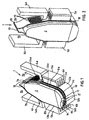
- Fig. 1 shows a print head attachment 1 incorporating the steps according to the invention.
- the print head attachment 1 comprises a baseplate 2, for example of ceramic material, the top part of which is provided with two oblique sides 7a, and beneath that two parallel sides 8a and 8b, and beneath the latter curved surfaces 9a, 9b, which at the bottom merge into a head surface 9c.
- Ink ducts 16a, 16b are milled in the sides or surfaces 7a, 8a, 9a, 9c, on the one hand, and 7b, 8b, 9b and 9c, on the other hand. These ducts am covered from the outside by a single foil 10, which is trained around the baseplate 2 in the manner shown in the drawings, and fixed thereon.
- This foil may be a ceramic foil, a metal foil or a plastic film.
- the foil 10 is provided with a relatively thick portion 11, e.g. o.1 mm thick, formed with through holes or nozzles 17 which are in line with the ends of the ducts 16a, 16b.
- Curved foil portions 12a, 12b are located on either side of the foil portion 11 and cover the ducts 16a, 16b in the transition zone 9a, 9b to the sides 8a, 8b.
- the foil 10 is then continued in relatively thin portions 13a, 13b, e.g. 0.02 mm thick, which form a flexible top boundary of the ducts 16a, 16b, which are subject to the action of the legs 6a, 6b of piezo-electric elements or actuators 5a, 5b.
- the foil 10 then continues upwardly with portions 14a, 14b, which can also be relatively thin and in which filter passages 15 are provided, each in register with one of the ducts 16a or 16b respectively.
- a plurality of filter passages can be provided for each duct, e.g. a longitudinal row or an array or even an arbitrary screen provided with holes which are much smaller than the width of the ducts.
- the filter passages can be made by a laser machining of the foil and have a diameter of 0.01 mm, for example, but other techniques can be used, such as etching, electroforming and sandblasting.
- the filter passages 15 form the downstream boundary of ink distribution chambers 3a, 3b, which are also bounded by walls 4a, 4b, which here are shown purely diagrammatically, it being understood that they effectively surround the distribution chambers 3a, 3b.
- the drawing does not show the way in which the ink distribution chambers are connected to an ink source.
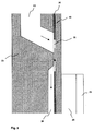
- Fig. 3 shows a printhead attachment 21 which comprises a baseplate 22, for example of ceramic material, provided with ink ducts 36 milled in a side of the surface of the baseplate, as well as one or more ink distribtion chambers 23, which discharge into the same surface of the baseplate.
- the filter means between the ink distribution chamber and the upstream end of the ink ducts come about by covering said surface of the baseplate with a foil 30, which comprises relatively large openings 35, for example round openings with a diameter of 1 mm.
- An opening 35 forms an overlap with the ink distribution chamber and the upstream end of one or more ink ducts.
- this foil which for example is constituted of metal or plastic, with a continuous foil 40, a narrow passage with a width equal to the thickness of the foil (for example 0.01 mm), arises between the ink distribution chamber and the connected ink ducts.
- the ink flows through the passage in a direction indicated by arrows in figure 3.
- the foils 30 and 40 are continued to form a flexible top boundary of the ink ducts, and are subjected to the action of the legs 26 of a piezo-electric element 25.
- An advantage of this embodiment is that the ink distribution chamber as well as the ink ducts can be incorporated in the same baseplate, without the need for physically separating them to insert the filter means.
- the resulting shape of the filter passages and surrounding cavities doesn't allow air bubbles to accumulate near or in the filter means.
- the narrow passages can be created by introducing relatively large openings, which are easy to produce, in the foil 30, since the width of the passage in the direction of the ink flow is defined only by the thickness of the foil.
- An important advantage of the large openings is that clogging of the filter passages is almost prevented, since in a direction perpendicular to the ink flow the width of the passages can be as large as the diameter of the opening 35.
- one thicker foil is used in stead of two separate foils 30 and 40.
- a narrow passage of the same shape can be formed between the ink distribution chamber and the ink ducts.
- one foil is used to cover the side of the baseplate.
Landscapes
- Particle Formation And Scattering Control In Inkjet Printers (AREA)
Abstract
Description
- The invention relates to a device for delivering ink, more particularly on a print head for an ink jet printer, provided with a series of ink delivery nozzles which can be actuated selectively in the printing of a sheet of paper or the like.
- The invention also relates to an ink jet printer provided with such a device.
- A known printer head is provided with a base body or base plate with two fiat sides and a head surface, a series of parallel ink ducts being provided in each side and merging near the corner to the head surface into ink tunnels which extend through the base body to the head surface. The ink ducts originate from an ink distribution chamber provided in the associated side and connected via an internal passage to the ink inlet provided in the body. To prevent any irregularities from occurring in the ink ducts and then obstructing the throughflow, a filter is provided in the distribution chamber at the downstream end of the passage between the inlet and the distribution chamber. This filter is placed in the distribution chamber from the exterior, after which a foil is placed over the ink ducts and over the distribution chamber.
- One disadvantage of this arrangement is that air bubbles liberated in the distribution chamber can readily enter the ink passages and in the long term may interfere with the ink delivery in the associated ink passages. If the filter is dogged, ink may be withdrawn from a neighbouring duct.
- The object of the invention is to provide an improvement In this respect. To this end, according to one aspect of the invention, there is provided a device for delivering ink to a sheet of paper or the like, comprising a body with sides and a head end at an angle to the sides and containing an inlet for the ink originating from a reservoir, with a number of ink delivery nozzles at the head end and a number of ink passages extending between the inlet and the ink delivery nozzles, along one or more of the sides with means located at the ink passages on that side for the selective propulsion of ink therethrough to the ink delivery nozzles, wherein filter means are provided between the reservoir and the ink passages and are disposed in a distribution chamber directly at the upstream end of the ink passages.
- Thus a (secondary) filter is created for each ink passage, so that when passing to the ink passages not only are any impurities removed from the ink but, in addition, any air bubbles in the ink are prevented from flowing in the ink passages. The possible mutual influence of the pressures in the ink passages is also greatly minimised by the closure provided by the filter in respect of the upstream inlets of the ink passages, and the filter therefore has an excellent restricting effect.
- It should be noted that US patent 4 364 067 discloses a print head having a substantially triangular base body or baseplate in cross-section, disposed with the apex towards the paper for printing and provided at the top with two ink inlets situated at the top ends of the oblique sides and communicating with an ink reservoir, and each leading by internal passages to an ink distribution chamber, to which there are connected a number of ducts disposed in the associated oblique side. These ducts converge with an arc in the plane of the associated oblique side towards a number of obliquely directed ink delivery nozzles. Grooves are formed in the upstream ends of the ducts by means of which the ink is filtered. A disadvantage of this construction is that making the grooves in the ducts requires considerable care.
- According to another feature of the invention, the distribution chamber is disposed on the outside of the body and the ink passages are separated from the distribution chamber by means of a layer of material which is disposed on the body and in which filter passages are provided which correspond to the ink passages. Thus use is made of the chosen position of the secondary filter in order to simplify the body since there is no need for any passages between the inlet and the distribution chamber. In fact, the filter passages then form the inlet to the body.
- In another development thereof, the ink propulsion means comprise selectively actuatable piezo-electric elements, wherein an ink-tight layer, such as a suitable foil, extends between the piezo-electric elements and the ducts, wherein the ink-tight layer is formed as a unit with the layer of material provided with filter passages. Thus the filter can be mounted in one operation with the ink-tight layer for the ink propulsion means.
- Preferably, the ink delivery nozzles are formed by the same ink-tight layer provided with a number of ink delivery passages in line with the ends of the ink passages and extending through the layer.
- Also, preferably, the body is provided with two opposite sides in which the ink passages provided with filter means are disposed in comparable manner. If the Ink passages over the path extending from the filter means to the ink delivery nozzles are formed as through ducts in the associated side and the adjoining head end of the body and are covered by the same ink-tight layer, one and the same ink-tight layer can be disposed (with a filter) around the body in order to perform a plurality of functions simultaneously.
- The invention will now be explained with reference to the exemplified embodiments illustrated in the accompanying drawings wherein:
- Fig. 1 is a bottom perspective view of one exemplified embodiment of the device according to the invention and
- Fig. 2 is a perspective view obliquely from above of the device shown in Fig. 1.
- Fig. 3 is a cross-section of another embodiment of the device according to the invention.
-
- Fig. 1 shows a print head attachment 1 incorporating the steps according to the invention. The print head attachment 1 comprises a
baseplate 2, for example of ceramic material, the top part of which is provided with twooblique sides 7a, and beneath that twoparallel sides 8a and 8b, and beneath the lattercurved surfaces head surface 9c.Ink ducts surfaces single foil 10, which is trained around thebaseplate 2 in the manner shown in the drawings, and fixed thereon. - This foil may be a ceramic foil, a metal foil or a plastic film.
- In the bottom part, the
foil 10 is provided with a relativelythick portion 11, e.g. o.1 mm thick, formed with through holes ornozzles 17 which are in line with the ends of theducts foil portions foil portion 11 and cover theducts transition zone sides 8a, 8b. - The
foil 10 is then continued in relativelythin portions ducts legs actuators foil 10 then continues upwardly withportions filter passages 15 are provided, each in register with one of theducts filter passages 15 form the downstream boundary ofink distribution chambers 3a, 3b, which are also bounded bywalls distribution chambers 3a, 3b. The drawing does not show the way in which the ink distribution chambers are connected to an ink source. - Fig. 3 shows a printhead attachment 21 which comprises a
baseplate 22, for example of ceramic material, provided withink ducts 36 milled in a side of the surface of the baseplate, as well as one or moreink distribtion chambers 23, which discharge into the same surface of the baseplate. - The filter means between the ink distribution chamber and the upstream end of the ink ducts come about by covering said surface of the baseplate with a
foil 30, which comprises relativelylarge openings 35, for example round openings with a diameter of 1 mm. An opening 35 forms an overlap with the ink distribution chamber and the upstream end of one or more ink ducts. By covering this foil, which for example is constituted of metal or plastic, with acontinuous foil 40, a narrow passage with a width equal to the thickness of the foil (for example 0.01 mm), arises between the ink distribution chamber and the connected ink ducts. - The ink flows through the passage in a direction indicated by arrows in figure 3. The
foils legs 26 of a piezo-electric element 25. - An advantage of this embodiment is that the ink distribution chamber as well as the ink ducts can be incorporated in the same baseplate, without the need for physically separating them to insert the filter means. The resulting shape of the filter passages and surrounding cavities doesn't allow air bubbles to accumulate near or in the filter means.
- Another advantage is that the narrow passages can be created by introducing relatively large openings, which are easy to produce, in the
foil 30, since the width of the passage in the direction of the ink flow is defined only by the thickness of the foil. An important advantage of the large openings is that clogging of the filter passages is almost prevented, since in a direction perpendicular to the ink flow the width of the passages can be as large as the diameter of theopening 35. - In another embodiment of a device according to the invention, one thicker foil is used in stead of two
separate foils - In a further embodiment also one foil is used to cover the side of the baseplate. By removing a thin slice of material of the baseplate (for example 0.01 mm thick) between the ink distribution chamber and the upstream ends of one or more ink ducts, again a narrow passage arises when the baseplate is covered by a continuous foil. An advantage of this embodiment is that there is no need for introducing a recess in the foil.
Claims (8)
- A device for delivering ink to a sheet of paper or the like, comprising a body with sides and a head end at an angle to the sides and containing an inlet for the ink originating from a reservoir, with a number of ink delivery nozzles at the head end and a number of ink passages extending between the inlet and the ink delivery nozzles, along one or more of the sides, with means located at the ink passages on that side for the selective propulsion of ink therethrough to the ink delivery nozzles, wherein filter means are provided between the reservoir and the ink passages and are disposed in a distribution chamber at the upstream end of the ink passages.
- A device according to claim 1, wherein the distribution chamber is disposed on the outside of the body and the ink passages are separated from the distribution chamber by means of a layer of material in which filter passages are provided which correspond to the ink passages.
- A device according to claim 2, wherein the ink propulsion means comprise selectively actuatable piezo-electric elements, wherein an ink-tight layer, such as a suitable foil, extends between the piezo-electric elements and the ducts, wherein the ink-tight layer is formed as a unit with the layer of material provided with filter passages.
- A device according to claim 3, wherein the ink delivery nozzles are formed by the same ink-tight layer provided with a number of ink delivery passages in line with the ends of the ink passages and extending through the layer.
- A device according to any one of the preceding claims, wherein the body is provided with two opposite sides in which the ink passages with filter means are disposed in comparable manner.
- A device according to claim 4 or 5, wherein the ink passages over the path extending from the filter means to the ink delivery nozzles are formed as through ducts in the associated side and the adjoining head end of the body and are covered by the same ink-tight layer.
- A device according to claim 1, wherein the body comprises the distribution chamber, and the ink passages are separated from the distribution chamber by means of filter passages situated between the baseplate and a layer of material disposed on a side of said body.
- A printer provided with a device according to any one of the preceding claims.
Applications Claiming Priority (2)
| Application Number | Priority Date | Filing Date | Title |
|---|---|---|---|
| NL1011127A NL1011127C2 (en) | 1999-01-25 | 1999-01-25 | Ink delivery device. |
| NL1011127 | 1999-01-25 |
Publications (2)
| Publication Number | Publication Date |
|---|---|
| EP1022145A1 true EP1022145A1 (en) | 2000-07-26 |
| EP1022145B1 EP1022145B1 (en) | 2007-01-17 |
Family
ID=19768536
Family Applications (1)
| Application Number | Title | Priority Date | Filing Date |
|---|---|---|---|
| EP00200126A Expired - Lifetime EP1022145B1 (en) | 1999-01-25 | 2000-01-14 | Ink jet array |
Country Status (5)
| Country | Link |
|---|---|
| US (1) | US6309061B1 (en) |
| EP (1) | EP1022145B1 (en) |
| JP (1) | JP2000272123A (en) |
| DE (1) | DE60032955T2 (en) |
| NL (1) | NL1011127C2 (en) |
Citations (7)
| Publication number | Priority date | Publication date | Assignee | Title |
|---|---|---|---|---|
| US3645448A (en) * | 1969-11-17 | 1972-02-29 | Mead Corp | Inlet plate for a coating head |
| US4364067A (en) | 1979-10-29 | 1982-12-14 | Kabushiki Kaisha Suwa Seikosha | Highly integrated ink jet head |
| JPS59167267A (en) * | 1983-03-15 | 1984-09-20 | Nec Corp | Multi-nozzle printing head |
| US4514743A (en) * | 1983-04-12 | 1985-04-30 | Nixdorf Computer Ag | Ink jet filtered-chamber print head |
| JPH01186331A (en) * | 1988-01-20 | 1989-07-25 | Ricoh Co Ltd | Liquid jet recording head |
| JPH0499634A (en) * | 1990-08-18 | 1992-03-31 | Seikosha Co Ltd | Ink jet head |
| EP0867289A1 (en) * | 1994-04-20 | 1998-09-30 | Seiko Epson Corporation | Inkjet recording apparatus |
Family Cites Families (3)
| Publication number | Priority date | Publication date | Assignee | Title |
|---|---|---|---|---|
| JPS60198255A (en) * | 1984-03-23 | 1985-10-07 | Canon Inc | liquid jet recording device |
| IT1183958B (en) * | 1985-09-17 | 1987-10-22 | Olivetti & Co Spa | PERFECTED INK JET PRINT HEAD |
| JP2639805B2 (en) * | 1987-04-17 | 1997-08-13 | 富士通株式会社 | Phase change ink ejection device |
-
1999
- 1999-01-25 NL NL1011127A patent/NL1011127C2/en not_active IP Right Cessation
-
2000
- 2000-01-12 JP JP2000003447A patent/JP2000272123A/en active Pending
- 2000-01-12 US US09/481,393 patent/US6309061B1/en not_active Expired - Lifetime
- 2000-01-14 EP EP00200126A patent/EP1022145B1/en not_active Expired - Lifetime
- 2000-01-14 DE DE60032955T patent/DE60032955T2/en not_active Expired - Lifetime
Patent Citations (7)
| Publication number | Priority date | Publication date | Assignee | Title |
|---|---|---|---|---|
| US3645448A (en) * | 1969-11-17 | 1972-02-29 | Mead Corp | Inlet plate for a coating head |
| US4364067A (en) | 1979-10-29 | 1982-12-14 | Kabushiki Kaisha Suwa Seikosha | Highly integrated ink jet head |
| JPS59167267A (en) * | 1983-03-15 | 1984-09-20 | Nec Corp | Multi-nozzle printing head |
| US4514743A (en) * | 1983-04-12 | 1985-04-30 | Nixdorf Computer Ag | Ink jet filtered-chamber print head |
| JPH01186331A (en) * | 1988-01-20 | 1989-07-25 | Ricoh Co Ltd | Liquid jet recording head |
| JPH0499634A (en) * | 1990-08-18 | 1992-03-31 | Seikosha Co Ltd | Ink jet head |
| EP0867289A1 (en) * | 1994-04-20 | 1998-09-30 | Seiko Epson Corporation | Inkjet recording apparatus |
Non-Patent Citations (3)
| Title |
|---|
| PATENT ABSTRACTS OF JAPAN vol. 009, no. 022 (M - 354) 30 January 1985 (1985-01-30) * |
| PATENT ABSTRACTS OF JAPAN vol. 013, no. 473 (M - 884) 26 October 1989 (1989-10-26) * |
| PATENT ABSTRACTS OF JAPAN vol. 016, no. 335 (M - 1283) 21 July 1992 (1992-07-21) * |
Also Published As
| Publication number | Publication date |
|---|---|
| DE60032955D1 (en) | 2007-03-08 |
| JP2000272123A (en) | 2000-10-03 |
| US6309061B1 (en) | 2001-10-30 |
| NL1011127C2 (en) | 2000-07-27 |
| EP1022145B1 (en) | 2007-01-17 |
| DE60032955T2 (en) | 2007-11-08 |
Similar Documents
| Publication | Publication Date | Title |
|---|---|---|
| US7753513B2 (en) | Ink-jet head, filter assembly used for manufacturing the ink-jet head, and method for manufacturing the ink-jet head using the filter assembly | |
| EP2602116A1 (en) | Ink jet print head | |
| JP4314981B2 (en) | Inkjet head | |
| JP4507170B2 (en) | Inkjet printer head | |
| EP1905593B1 (en) | Ink-jet head | |
| JP4235819B2 (en) | Inkjet recording head | |
| JP3922004B2 (en) | Inkjet printer head | |
| JP3885783B2 (en) | Inkjet head | |
| EP1022145A1 (en) | Ink jet array | |
| US7303270B2 (en) | Ink-jet head | |
| JP4983001B2 (en) | Inkjet head | |
| JP7188001B2 (en) | Liquid ejector | |
| JP4492524B2 (en) | Inkjet head | |
| EP1506866B1 (en) | Ink-jet head | |
| EP1022141B1 (en) | Ink jet array | |
| JP4662023B2 (en) | Inkjet head | |
| JP3841036B2 (en) | Inkjet head | |
| JP4643294B2 (en) | Head maintenance device | |
| JP2006088647A (en) | Inkjet recording head | |
| JP4387535B2 (en) | Inkjet array | |
| JP4917703B2 (en) | Inkjet printer head | |
| JP2008207542A (en) | Droplet discharge head | |
| JP2007229949A (en) | Ink jet head and manufacturing method thereof | |
| JP2005178129A (en) | Printer head, printer and printer head manufacturing method |
Legal Events
| Date | Code | Title | Description |
|---|---|---|---|
| PUAI | Public reference made under article 153(3) epc to a published international application that has entered the european phase |
Free format text: ORIGINAL CODE: 0009012 |
|
| AK | Designated contracting states |
Kind code of ref document: A1 Designated state(s): DE FR GB NL |
|
| AX | Request for extension of the european patent |
Free format text: AL;LT;LV;MK;RO;SI |
|
| 17P | Request for examination filed |
Effective date: 20010126 |
|
| AKX | Designation fees paid |
Free format text: DE FR GB NL |
|
| GRAP | Despatch of communication of intention to grant a patent |
Free format text: ORIGINAL CODE: EPIDOSNIGR1 |
|
| GRAS | Grant fee paid |
Free format text: ORIGINAL CODE: EPIDOSNIGR3 |
|
| GRAA | (expected) grant |
Free format text: ORIGINAL CODE: 0009210 |
|
| AK | Designated contracting states |
Kind code of ref document: B1 Designated state(s): DE FR GB NL |
|
| REG | Reference to a national code |
Ref country code: GB Ref legal event code: FG4D |
|
| REF | Corresponds to: |
Ref document number: 60032955 Country of ref document: DE Date of ref document: 20070308 Kind code of ref document: P |
|
| ET | Fr: translation filed | ||
| PLBE | No opposition filed within time limit |
Free format text: ORIGINAL CODE: 0009261 |
|
| STAA | Information on the status of an ep patent application or granted ep patent |
Free format text: STATUS: NO OPPOSITION FILED WITHIN TIME LIMIT |
|
| 26N | No opposition filed |
Effective date: 20071018 |
|
| REG | Reference to a national code |
Ref country code: FR Ref legal event code: PLFP Year of fee payment: 17 |
|
| PGFP | Annual fee paid to national office [announced via postgrant information from national office to epo] |
Ref country code: NL Payment date: 20160121 Year of fee payment: 17 |
|
| PGFP | Annual fee paid to national office [announced via postgrant information from national office to epo] |
Ref country code: DE Payment date: 20160120 Year of fee payment: 17 |
|
| PGFP | Annual fee paid to national office [announced via postgrant information from national office to epo] |
Ref country code: GB Payment date: 20160120 Year of fee payment: 17 Ref country code: FR Payment date: 20160121 Year of fee payment: 17 |
|
| REG | Reference to a national code |
Ref country code: DE Ref legal event code: R119 Ref document number: 60032955 Country of ref document: DE |
|
| REG | Reference to a national code |
Ref country code: NL Ref legal event code: MM Effective date: 20170201 |
|
| GBPC | Gb: european patent ceased through non-payment of renewal fee |
Effective date: 20170114 |
|
| REG | Reference to a national code |
Ref country code: FR Ref legal event code: ST Effective date: 20170929 |
|
| PG25 | Lapsed in a contracting state [announced via postgrant information from national office to epo] |
Ref country code: FR Free format text: LAPSE BECAUSE OF NON-PAYMENT OF DUE FEES Effective date: 20170131 |
|
| PG25 | Lapsed in a contracting state [announced via postgrant information from national office to epo] |
Ref country code: GB Free format text: LAPSE BECAUSE OF NON-PAYMENT OF DUE FEES Effective date: 20170114 Ref country code: NL Free format text: LAPSE BECAUSE OF NON-PAYMENT OF DUE FEES Effective date: 20170201 Ref country code: DE Free format text: LAPSE BECAUSE OF NON-PAYMENT OF DUE FEES Effective date: 20170801 |