EP1021639B1 - A cutting bit assembly for impinging an earth strata - Google Patents
A cutting bit assembly for impinging an earth strata Download PDFInfo
- Publication number
- EP1021639B1 EP1021639B1 EP97938375A EP97938375A EP1021639B1 EP 1021639 B1 EP1021639 B1 EP 1021639B1 EP 97938375 A EP97938375 A EP 97938375A EP 97938375 A EP97938375 A EP 97938375A EP 1021639 B1 EP1021639 B1 EP 1021639B1
- Authority
- EP
- European Patent Office
- Prior art keywords
- cutting bit
- chuck
- pin
- holder
- recess
- Prior art date
- Legal status (The legal status is an assumption and is not a legal conclusion. Google has not performed a legal analysis and makes no representation as to the accuracy of the status listed.)
- Expired - Lifetime
Links
- 230000005291 magnetic effect Effects 0.000 claims description 82
- 230000014759 maintenance of location Effects 0.000 claims description 34
- 230000000717 retained effect Effects 0.000 claims description 2
- 229910000831 Steel Inorganic materials 0.000 description 9
- 239000010959 steel Substances 0.000 description 9
- 230000005294 ferromagnetic effect Effects 0.000 description 3
- 229910001104 4140 steel Inorganic materials 0.000 description 2
- 230000015572 biosynthetic process Effects 0.000 description 2
- 239000003245 coal Substances 0.000 description 2
- 238000005755 formation reaction Methods 0.000 description 2
- 238000005065 mining Methods 0.000 description 2
- 238000003466 welding Methods 0.000 description 2
- 229910001350 4130 steel Inorganic materials 0.000 description 1
- 239000004593 Epoxy Substances 0.000 description 1
- VTLYFUHAOXGGBS-UHFFFAOYSA-N Fe3+ Chemical compound [Fe+3] VTLYFUHAOXGGBS-UHFFFAOYSA-N 0.000 description 1
- 238000010276 construction Methods 0.000 description 1
- 239000002826 coolant Substances 0.000 description 1
- 230000008878 coupling Effects 0.000 description 1
- 238000010168 coupling process Methods 0.000 description 1
- 238000005859 coupling reaction Methods 0.000 description 1
- 238000003780 insertion Methods 0.000 description 1
- 230000037431 insertion Effects 0.000 description 1
- JEIPFZHSYJVQDO-UHFFFAOYSA-N iron(III) oxide Inorganic materials O=[Fe]O[Fe]=O JEIPFZHSYJVQDO-UHFFFAOYSA-N 0.000 description 1
- 238000000034 method Methods 0.000 description 1
- 229910001172 neodymium magnet Inorganic materials 0.000 description 1
- 239000011435 rock Substances 0.000 description 1
Images


Classifications
-
- E—FIXED CONSTRUCTIONS
- E21—EARTH OR ROCK DRILLING; MINING
- E21B—EARTH OR ROCK DRILLING; OBTAINING OIL, GAS, WATER, SOLUBLE OR MELTABLE MATERIALS OR A SLURRY OF MINERALS FROM WELLS
- E21B10/00—Drill bits
- E21B10/60—Drill bits characterised by conduits or nozzles for drilling fluids
-
- E—FIXED CONSTRUCTIONS
- E21—EARTH OR ROCK DRILLING; MINING
- E21C—MINING OR QUARRYING
- E21C35/00—Details of, or accessories for, machines for slitting or completely freeing the mineral from the seam, not provided for in groups E21C25/00 - E21C33/00, E21C37/00 or E21C39/00
- E21C35/18—Mining picks; Holders therefor
- E21C35/183—Mining picks; Holders therefor with inserts or layers of wear-resisting material
- E21C35/1831—Fixing methods or devices
-
- E—FIXED CONSTRUCTIONS
- E21—EARTH OR ROCK DRILLING; MINING
- E21C—MINING OR QUARRYING
- E21C35/00—Details of, or accessories for, machines for slitting or completely freeing the mineral from the seam, not provided for in groups E21C25/00 - E21C33/00, E21C37/00 or E21C39/00
- E21C35/18—Mining picks; Holders therefor
- E21C35/19—Means for fixing picks or holders
-
- F—MECHANICAL ENGINEERING; LIGHTING; HEATING; WEAPONS; BLASTING
- F16—ENGINEERING ELEMENTS AND UNITS; GENERAL MEASURES FOR PRODUCING AND MAINTAINING EFFECTIVE FUNCTIONING OF MACHINES OR INSTALLATIONS; THERMAL INSULATION IN GENERAL
- F16B—DEVICES FOR FASTENING OR SECURING CONSTRUCTIONAL ELEMENTS OR MACHINE PARTS TOGETHER, e.g. NAILS, BOLTS, CIRCLIPS, CLAMPS, CLIPS OR WEDGES; JOINTS OR JOINTING
- F16B21/00—Means for preventing relative axial movement of a pin, spigot, shaft or the like and a member surrounding it; Stud-and-socket releasable fastenings
- F16B21/10—Means for preventing relative axial movement of a pin, spigot, shaft or the like and a member surrounding it; Stud-and-socket releasable fastenings by separate parts
- F16B21/12—Means for preventing relative axial movement of a pin, spigot, shaft or the like and a member surrounding it; Stud-and-socket releasable fastenings by separate parts with locking-pins or split-pins thrust into holes
Definitions
- Tools which impinge the earth strata include rotatable cutting bits (e.g., point attack mine tools, construction tools, and the like) which include a hard insert at the axially forward end. These rotatable cutting bits are rotatably mounted within the bore of a holder (or block) and held therein by a retainer.
- rotatable cutting bits e.g., point attack mine tools, construction tools, and the like
- These rotatable cutting bits are rotatably mounted within the bore of a holder (or block) and held therein by a retainer.
- a plurality of holders mount to a driven member (e.g., a drum or wheel) which is driven under the influence of a driver (e.g., a motor).
- a driven member e.g., a drum or wheel
- a driver e.g., a motor
- a road planing drum laced with road planing tools e.g., a road planing drum laced with road planing tools. It can be appreciated that, using present techniques, it is time-consuming for the operator to change an entire drum of cutting bits. It thus would be desirable to provide a cutting bit assembly that provides a secure connection between the cutting bit and the holder yet permits the relatively easy connection or removal of the cutting bit to the holder.
- Tools which impinge the earth strata further include a roof bit with a hard insert at the axially forward end (i.e., impingement end) thereof wherein the roof bit non-rotatably connects, either directly or through a chuck or other type of connector, to a driver member.
- Driving the driver member causes the roof bit to be driven, which typically is in a rotary fashion. In order to secure the driver member to the roof bit, it is important that there be a secure connection between the roof bit and the driver member.
- a steel retainer pin having a shank and a serrated head has been used to secure a roof bit to a chuck (or coupling).
- the roof bit body contains a hole which registers with a hole in the chuck.
- the shank of the retainer pin passes through the hole in the roof bit and into the hole in the chuck.
- the retainer pin is forced into the hole in the roof bit so that the serrated head engages the periphery of the roof bit body that defines the hole so as to secure the roof bit to the chuck.
- the invention is a cutting bit assembly which comprises a driven member and a cutting bit detachably connected to the driven member by a retainer.
- the retainer includes a magnetic pin that removably engages at least one of the cutting bit and the driven member.
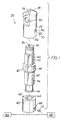
- FIGS. 1 and 2 illustrate a specific embodiment of a roof bit assembly generally designated as 20.
- Roof bit assembly 20 includes a cutting bit (or roof bit) 22 which has an axially forward end 24 and an axially rearward end 26.
- the cutting insert 28 is of the style shown and described in issued US-A-5 172 775, to Sheirer et al., for a Rotary Drill Bit Assembly (assigned to the assignee of the present patent application).
- Cutting bit 22 contains a cavity 30 therein which has an opening 32 at the rearward end 26 of the cutting bit 22.
- Cutting bit 22 further includes a bit wall 34 which contains a passage 36 that passes completely therethrough so as to communicate with the cavity 30.
- Roof bit assembly 20 further includes a chuck 40 which has an axially forward end 42 and an axially rearward end 44.
- a generally cylindrical passage 46 passes through the entire length of the chuck 40.
- the chuck 40 has an enlarged diameter portion 48 which separates the chuck 40 into an axially forward portion 50 and an axially rearward portion 52.
- the chuck 40 contains a generally cylindrical blind recess (or hole) 54 in the exterior surface of the axially forward portion 50 thereof.
- the chuck 40 further contains a generally cylindrical blind recess (or hole) 56 in the exterior surface of the axially rearward portion 52 thereof.
- Roof bit assembly 20 also includes a drill rod 60 which has an axially forward end 62 and an axially rearward end (not illustrated).
- Drill rod 60 presents a bore 64 which has an opening at the axially forward end thereof.
- the drill rod 60 also contains a hole 65, which as will become apparent registers with blind recess 56 upon assembly, adjacent to the axially forward end 62.
- the drill rod 60 operatively connects to a driver 66 and a pressurized source of coolant 68.
- a magnetic pin 70 passes through passage 36 and into blind recess (or hole) 54 so as to connect the cutting bit 22 to the chuck 40.
- Another magnetic pin 72 passes through hole 65 in the drill rod 60 and into blind recess 56 so as to connect the chuck 40 to the drill rod 60.
- the cutting bit 22, the chuck 40, and the drill rod 60 are each made from a ferromagnetic steel.
- Exemplary grades (AISI) of steel for these components include 15B35 steel for the cutting bit, 4140 steel for the chuck, and 4130 steel for the drill rod.
- AISI ferromagnetic steel
- the magnetic strength of the magnetic pin 70 i.e., the magnetic attraction between the magnetic pin 70 and the cutting bit 22 and chuck 40, is sufficiently great so that the magnetic pin 70 remains in place to securely connect the cutting bit 22 to the chuck 40 during the operation of the roof bit.
- the magnetic strength of the magnetic pin 72 i.e., the magnetic attraction between the magnetic pin 72 and the chuck 40 and the drill rod 60, is sufficiently great so that the magnetic pin 72 remains in place to securely connect the chuck 40 and the drill rod 60 during the operation of the roof bit.
- the operator can take a magnet, which has an attractive magnetic strength with respect to the magnetic pin 70 that is greater than the magnetic attraction between the magnetic pin and the cutting bit 22 and chuck 40, and position the magnet near the magnetic pin 70 so as to remove the magnetic pin 70 from the passage 36 and the recess 54.
- the operator could also use a puller or some type of gripper (or pliers) to grip or pull the magnetic pin out of engagement with the roof bit and the chuck.
- the magnetic pin could have a head or some other structure which would facilitate the operator to obtain a firm grip on the pin.
- the cutting bit can be removed from the chuck and a new cutting bit 22 can then be positioned on the chuck 40.
- the magnetic pin 70 is then passed through the passage 36 and into the recess 54 of the chuck so as to securely connect the new cutting bit 22 to the chuck 40.
- the magnetic pin 70 may be reused in conjunction with the new cutting bit.
- magnetic pin 72 can be magnetically or physically removed from engagement with the chuck 40 and the drill rod 60 so as to disconnect the same.
- Magnetic pin 72 can be physically inserted through hole 65 into engagement with blind recess 56 in the chuck 40 so as to secure the same together.
- the magnetic pins are easy to insert and remove which is in contrast to earlier retention arrangements.
- the magnetic pins do not break during the assembly or disassembly of the cutting bit from the chuck, or the chuck from the drill rod, as has been the case in the past.
- the magnetic pins are reusable and a portion is not left in the roof bit body (as with the serrated type retainer) making the roof bit bodies easier to recycle.
- a roof bit which was made of 15B35 steel, was secured to a chuck, which was made of 4140 steel, via a magnetic pin (such as is shown in FIGS. 1 and 2, except that there was only one magnetic pin to secure the roof bit to the chuck) for testing.
- the roof bit had a one inch diameter and except for the passage, was structurally similar to a Kennametal KCV4-1 inch style of roof bit.
- the magnetic pin was a 1/4 inch (6.35mm) diameter by 1/4 inch (6.35mm) long cylinder of a neodymium iron boron magnet sold under the trademark Duracore by Nortronics Company, Inc., of Minneapolis, Minnesota.
- the roof bit-chuck connection was tested at a rotational speed of about 1100 revolution per minute (rpm) without the magnetic pin being thrown out under the influence of centrifugal force.
- the typical rotational speed for the operation of a roof bit is about 600 rpm.
- the magnetic pin has sufficient magnetic attraction so as to resist the centrifugal forces acting thereon during rotation.
- the magnetic strength of the magnetic pin (70, 72) can be selected depending upon the strength required for the specific application. In this regard, a ferric iron magnet may be suitable for many applications.
- FIGS. 3 and 4 there is shown an embodiment of the invention in which there is a rotatable cutting bit 80 with a hard insert 82 at the axially forward end 84 thereof and an annular groove 86 near the axially rearward end 88 thereof.
- the cutting bit 80 further includes a head portion 90 and a shank 92.
- a holder 94 (or block) contains a bore 96 which has an opening at each of the forward face 102 and the rearward face 104 of the holder 94.
- Holder 94 contains a cylindrical recess 106 in the rearward face 104 thereof.
- An integral boss 108 extends out from the holder 94 so as to be proximate to recess 106.
- Boss 108 includes an arcuate indention 110 in the bottom surface thereof.
- the holder 94 is mounted (typically as by welding) to a rotatable drum 111 such as, for example, a road planing drum or a coal mining drum.
- the holder 94 rotatably retains the cutting bit 80 in the bore 96 thereof by means of a generally U-shaped retention clip 112.
- Clip 112 has a body portion 114 with a pair of arms 116, 118 that depend therefrom.
- Retention clip 112 has an interior surface which comprises an arcuate portion 115 and a pair of straight portions 117 and 119 which correspond to arms 116 and 118, respectively.
- Retention clip 112 has a top surface 121.
- the arms (116, 118) extend through the groove 86, and because the spacing between straight portions 117 and 119 of the retention clip 112 is slightly larger than the diameter of the groove 86, the arms 116, 118 do not expand when the retention clip 112 is first received in the groove 86.
- the curvature of the arcuate portion 115 is about equal to the curvature of the groove 86 so that the arcuate portion 115 of the interior surface of the retention clip 112 is in physical contact with the surface of the groove 86 when the retention clip 112 is received in the groove 86.
- the operator passes a cylindrical magnetic pin 122 into the recess 106 so as to engage the arcuate indention 110 of the boss 108 and physically contact the top surface 121 of the retention clip 112.
- the boss 108 which is an integral part of the holder 94, is made from the ferromagnetic steel (e.g., AISI 8740 steel) that comprises the holder 94.
- AISI 8740 steel ferromagnetic steel
- the operator removes the magnetic pin 122 from recess 106 so that the pin 122 is out of engagement with the holder 94 and the retention clip 112. This can be done by physically removing the magnetic pin 122 using pliers or another type of gripper. The operator could also place a magnet near the magnetic pin 122 so as to draw it out of engagement with the holder 94 and the retention clip 112. For the magnet to draw the magnetic pin out of engagement, the magnetic attraction between the magnet and the magnetic pin must be greater than the magnetic attraction that maintains the magnetic pin in position.
- the retention clip 112 may then be removed from the groove 86 and the cutting bit 80 removed from the bore 96 of the holder 94.
- a new cutting bit 80 may then be positioned within the bore 96 of the holder 94, the retention clip 112 positioned so as to engage the groove 86, and the magnetic pin 122 repositioned in the recess 106 so as to engage the holder 94 and the retention pin 112 thereby providing for the secure rotatable retention of the cutting bit 80 in the holder 94.
- the magnetic pin may be reused in conjunction with the new cutting bit.
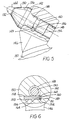
- FIGS. 5 and 6 there is shown a rotatable cutting bit 130 which has an axially forward end 132 and an axially rearward end 134.
- Cutting bit 130 has a head portion 136 and a shank portion 138.
- the shank portion 138 contains an annular groove 140 between the shoulder 142 and the rearward end 134 of the cutting bit 130.
- a hard insert 144 is at the axially forward end 132 of the cutting bit 130.
- a support (or block) 146 has a longitudinal bore 148 therein, and a transverse bore 149 which passes through a portion of the central bore 148.
- the transverse bore 149 includes a reduced diameter portion 151 and an enlarged diameter portion 153 with a shoulder 154 at the juncture thereof.
- the longitudinal axis of the bore 148 is generally coaxial with the central longitudinal axis of the cutting bit 130.
- the central axis of the transverse bore 149 is generally perpendicular to the central longitudinal axis of the longitudinal bore 148.
- Transverse bore 149 opens to each side surface 150, 152 of the support 146.
- Support 146 is connected (such as by welding or the like) to a rotatable drum 157.
- Cylindrical pin 156 is received within the transverse bore 149.
- Cylindrical pin 156 has an elongate body 158 and a protrusion 160 which extends from one end of the body 158.
- the diameter of the protrusion 160 is less than the diameter of the elongate body 158.
- the cylindrical pin 156 further includes a magnet 162 with a central aperture 164.
- the protrusion 160 passes through the aperture 164 so that there is a clearance fit therebetween.
- the magnetic attraction between the body 158 and the magnet 162 retains the magnet 162 on the body 158.
- the magnet 162 could be affixed to the protrusion 160 by epoxy or the like.
- the cylindrical pin 156 engages the groove 140 on the shank of the cutting bit and rotatably retains the cutting bit 130 within the bore 148 of the holder 146.
- the cylindrical pin 156 is positioned in the enlarged diameter portion 153 of the transverse bore 149 in such a fashion that the magnet 162 abuts against the shoulder 154.
- the support 146 is made of a ferromagnetic steel so that there is a magnetic attraction between the magnet 162 and the support 146. The magnetic attraction between the magnet 162 (of the cylindrical pin 156) and the holder 146 is great enough to retain the cylindrical pin 156 within the transverse bore 149 during operation.
- the cylindrical pin 156 rotatably retains the cutting bit 130 within the bore 148 of the holder 146 during the operation of the cutting bit-holder assembly.
- the operator may place a magnet in or near the enlarged diameter portion 153 of the transverse bore 149 and draws the cylindrical pin 156 out of the transverse bore 149.
- the magnetic attraction between the magnet and the cylindrical pin must be greater than the magnetic attraction that maintains the cylindrical pin in position.
- a pin or rod placed in the reduced diameter portion 151 of the transverse bore 149 may be used to push or punch the cylindrical pin 156 out of the transverse bore 149 via the enlarged diameter portion 153.
- the cutting bit 130 may then be removed from the longitudinal bore 148 of the holder 146.
- a new cutting bit 130 may be inserted into the bore 148 of the holder 146 and the cylindrical pin 156 reinserted into the transverse bore 149 so as to engage the groove 140 in the shank 138 of the cutting bit 130.
- the cutting bit 130 is now rotatably retained within the longitudinal bore 148 of the block 146.
- the cylindrical pin 156 may be reused in conjunction with the new cutting bit 130.
Landscapes
- Engineering & Computer Science (AREA)
- Mining & Mineral Resources (AREA)
- Geology (AREA)
- Life Sciences & Earth Sciences (AREA)
- Mechanical Engineering (AREA)
- General Life Sciences & Earth Sciences (AREA)
- Geochemistry & Mineralogy (AREA)
- General Engineering & Computer Science (AREA)
- Physics & Mathematics (AREA)
- Environmental & Geological Engineering (AREA)
- Fluid Mechanics (AREA)
- Drilling Tools (AREA)
- Earth Drilling (AREA)
- Processing Of Stones Or Stones Resemblance Materials (AREA)
Description
Claims (12)
- A cutting bit assembly (20) comprising:
a driven member (66; 111; 157) and a cutting bit (22; 80; 130) detachably connected to the driven member by a retainer,
characterized in that
the retainer includes a magnetic pin (70, 72; 122; 156) that removably engages at least one of the cutting bit (22; 80; 130) and the driven member (66; 111; 157). - The cutting bit assembly of claim 1 wherein the magnetic pin (70, 72) engages the cutting bit (22) and the driven member.
- The cutting bit assembly of claim 1 wherein the driven member (157) includes a holder (146) with a longitudinal bore (148) and a transverse bore (149), the cutting bit (130) having a groove (140), the cutting bit (130) being received within the longitudinal bore (148), and the magnetic pin (156) passing through the transverse bore (149) into engagement with the groove (140) so as to rotatably connect the cutting bit (130) to the holder (146).
- The cutting bit assembly of claim 1 wherein the driven member (111) includes a holder (94) with a bore (96) and a recess (106), the cutting bit (80) is received within the bore (96), the cutting bit (80) includes a groove (86), the retainer further including a retention clip (112) that engages the groove (86), and the magnetic pin (122) engages the retention clip (112) and the recess (106).
- The cutting bit assembly of claim 1 wherein the driven member (66) includes a chuck (40) having a recess (54), the cutting bit (22) includes a passage (36) therein, and the magnetic pin (72) passing through the passage (36) into engagement with the recess (54) so as to secure the cutting bit (22) to the chuck (40).
- The cutting bit assembly of claim 5 further including a drill rod (60), the drill rod containing a hole (65) therein, the chuck (40) containing another recess (56), and another magnetic pin (72) passing through the hole (65) in the drill rod and into engagement with the other recess (56) in the chuck so as to secure the chuck to the drill rod.
- The cutting bit assembly of claim 1 wherein the assembly is rotatable,the cutting bit (22) having an axially forward end (24) and an axially rearward end (26), at least one cutting insert (28) at the axially forward end (24) of the cutting bit (22);the cutting bit (22) containing a cavity (30) therein, the cavity (30) having an opening at the rearward end (26) of the cutting bit (22);the cutting bit (22) having a passage (36) therethrough so as to communicate with the cavity (30);the cutting bit assembly further comprises:a chuck (40) having an axially forward end (32) and an axially rearward end (44), the chuck (40) containing a recess (54) adjacent to the axially forward end (32) thereof;upon assembling the cutting bit (22) and the chuck (40), the axially forward end (42) of the chuck being received in the cavity (30) so that the passage (36) and the recess (54) are in alignment; andthe pin (70) being magnetically held in the recess (54) so as to non-rotatably secure the cutting bit (22) to the chuck (40).
- The rotatable cutting bit assembly of claim 7 wherein the magnetic attraction between the magnetic pin (70) and the cutting bit (22) and the chuck (40) is sufficiently great so that the magnetic pin (70) maintains its position relative to the chuck (40) and the cutting bit (22) during the operation of the cutting bit assembly.
- The rotatable cutting bit assembly of claim 7 further including a drill rod (60) which contains a hole (65) therein, and the chuck containing a second recess (56) adjacent to the axially rearward end (44) thereof, upon assembling the drill rod (60) and the chuck (40), the axially rearward end (44) of the chuck being received in the drill rod (60) so that the hole (65) in the drill rod and the second recess (56) in the chuck (40) are in alignment, and a second magnetic pin (72) being magnetically held in the hole (65) and the second recess (56) so as to non-rotatably secure the drill rod (60) to the chuck (40).
- The rotatable cutting bit assembly of claim 9 wherein the magnetic attraction between the second magnetic pin (72) and the drill rod (60) and the chuck (40) is sufficiently great so that the second magnetic pin (72) maintains its position relative to the chuck (40) and the drill rod (60) during the operation of the cutting bit assembly.
- The cutting bit assembly of claim 1 whereinthe cutting bit (130) has an axially forward end (132) and an axially rearward end (134);the cutting bit having an axially forward head portion (136) and an axially rearward shank portion (138), a hard insert (144) being at the axially forward end (132) of the cutting bit (130), and the shank (138) containing a groove (140) therein;the cutting bit assembly further comprises:a holder (146) having a longitudinal bore (148) and a transverse bore (149) intersecting the longitudinal bore (148); anda cylindrical pin (156) being received in the transverse bore (149) thereby engaging the groove (140) in the shank (138) of the cutting bit (130) so as to rotatably retain the cutting bit within the longitudinal bore (148) of the holder (146), and the cylindrical pin (156) being magnetically retained within the transverse bore (149).
- The cutting bit assembly of claim 1 whereinthe cutting bit (80) has a axially forward end (84) and an axially rearward end (88);the cutting bit (80) having an axially forward head portion (90) and an axially rearward shank portion (92), a hard insert (82) being at the axially forward end (84) of the cutting bit (80), and the shank (92) containing an annular recess (86) near the axially rearward end (88) thereof;the cutting bit assembly further comprises:a holder (94) having an axially forward face (102) and an axially rearward face (104), the holder (94) containing a longitudinal bore (96) having a rear opening at the axially rearward face (104) of the holder (94), and the holder further including a boss (108) projecting from the axially rearward face (104) thereof near the rear opening of the longitudinal bore, and the holder (94) further containing a blind bore (106) adjacent to the boss (108);when the cutter bit (80) and the holder (94) are assembled, the axially rearward end (88) of the cutter bit (80) extends past the axially rearward face (104) of the holder so as to expose the annular recess (86);a retention pin (112) being received in the annular recess (86); anda magnetic pin (122) being received by the blind bore (106) so as to engage the boss (108) and the retention pin (112) so as to maintain the retention pin (112) in position thereby rotatably retaining the cutting bit (80) within the longitudinal bore (96) of the holder (94).
Applications Claiming Priority (3)
| Application Number | Priority Date | Filing Date | Title |
|---|---|---|---|
| US08/720,904 US5833017A (en) | 1996-10-10 | 1996-10-10 | Cutting bit assembly for impinging an earth strata |
| US720904 | 1996-10-10 | ||
| PCT/US1997/014482 WO1998015714A1 (en) | 1996-10-10 | 1997-08-18 | A cutting bit assembly for impinging an earth strata |
Publications (2)
| Publication Number | Publication Date |
|---|---|
| EP1021639A1 EP1021639A1 (en) | 2000-07-26 |
| EP1021639B1 true EP1021639B1 (en) | 2001-11-21 |
Family
ID=24895736
Family Applications (1)
| Application Number | Title | Priority Date | Filing Date |
|---|---|---|---|
| EP97938375A Expired - Lifetime EP1021639B1 (en) | 1996-10-10 | 1997-08-18 | A cutting bit assembly for impinging an earth strata |
Country Status (10)
| Country | Link |
|---|---|
| US (1) | US5833017A (en) |
| EP (1) | EP1021639B1 (en) |
| JP (1) | JP2001501692A (en) |
| CN (1) | CN1234093A (en) |
| AU (1) | AU715972B2 (en) |
| CA (1) | CA2267306A1 (en) |
| DE (1) | DE69709793T2 (en) |
| PL (1) | PL186811B1 (en) |
| WO (1) | WO1998015714A1 (en) |
| ZA (1) | ZA977876B (en) |
Families Citing this family (27)
| Publication number | Priority date | Publication date | Assignee | Title |
|---|---|---|---|---|
| DE19725052C2 (en) * | 1997-06-13 | 1999-10-28 | Tracto Technik | Drill |
| US6886645B2 (en) | 2001-09-17 | 2005-05-03 | Kennametal Inc. | Liquid seal for wet roof bit |
| AU2003200561B9 (en) * | 2003-02-19 | 2009-07-02 | Sandvik Intellectual Property Ab | Drill bit |
| FR2858834B1 (en) * | 2003-08-14 | 2005-11-11 | Andre Jevanoff | IMPROVING PIN FIXING DEVICES |
| US7070011B2 (en) * | 2003-11-17 | 2006-07-04 | Baker Hughes Incorporated | Steel body rotary drill bits including support elements affixed to the bit body at least partially defining cutter pocket recesses |
| US7207400B2 (en) * | 2004-04-07 | 2007-04-24 | Kennametal Inc. | Coupler and roof drill bit assembly using such coupler |
| JP2006022593A (en) * | 2004-07-09 | 2006-01-26 | Giken Seisakusho Co Ltd | Excavation claw, holder, and excavation means |
| DE102004046719A1 (en) * | 2004-09-27 | 2006-04-06 | Gerd Elfgen | Chisel of a milling device |
| US7389833B2 (en) * | 2005-06-10 | 2008-06-24 | Keystone Drill Services, Inc. | Multi-sectional percussive drill bit assembly |
| AU2009204165B2 (en) * | 2008-01-08 | 2015-04-16 | Esco Group Llc | Tip for an earth working roll |
| US8534766B2 (en) * | 2008-04-22 | 2013-09-17 | Kennametal Inc. | Indexable cutting tool system |
| US8528990B2 (en) | 2009-01-22 | 2013-09-10 | Keystone Engineering & Manufacturing Corporation | Cutter with diamond bit tip |
| US20100181820A1 (en) * | 2009-01-22 | 2010-07-22 | Latham Winchester E | Wear insert and retainer |
| EP2499323A1 (en) * | 2009-02-27 | 2012-09-19 | Newtech Drilling Products, LLC. | Drill bit for earth boring |
| US8302708B1 (en) * | 2009-05-12 | 2012-11-06 | Dover Bmcs Acquisition Corporation | Rotational drill wrenches and drilling apparatuses including the same |
| US8881847B2 (en) | 2010-01-29 | 2014-11-11 | Kennametal Inc. | Dust collecting device for a roof tool |
| US8807248B2 (en) | 2011-03-23 | 2014-08-19 | Kennametal Inc. | Cutting insert for a roof drill bit |
| US9303460B2 (en) | 2012-02-03 | 2016-04-05 | Baker Hughes Incorporated | Cutting element retention for high exposure cutting elements on earth-boring tools |
| CN103170195B (en) * | 2013-03-26 | 2015-03-11 | 盐城福泰环保设备有限公司 | Filter bag frame for bag type dust collector |
| CN104963249A (en) * | 2015-07-02 | 2015-10-07 | 常州市瑞泰工程机械有限公司 | Rabble blade for excavating railway ballast |
| US10914050B2 (en) | 2018-11-07 | 2021-02-09 | Caterpillar Inc. | Adapter board with splined bushing |
| US11268507B2 (en) | 2019-05-21 | 2022-03-08 | Gardner Denver Petroleum Pumps, Llc | Fluid end of a hydraulic fluid pump and method of assembling the same |
| WO2022191888A1 (en) * | 2021-03-12 | 2022-09-15 | Nam Duy Nguyen | Fixed cutter rock bit with rotating cutter inserts |
| CN113463481A (en) * | 2021-05-14 | 2021-10-01 | 安徽优特公路养护科技有限公司 | Pavement drilling machine |
| US12601259B2 (en) * | 2021-07-15 | 2026-04-14 | Bit Service Company Ltd | Rebuildable hard surface cutting tip for mining bit |
| US11905947B2 (en) | 2021-10-29 | 2024-02-20 | Gd Energy Products, Llc | Fluid end of a hydraulic fluid pump and method of assembling the same |
| CN119957225B (en) * | 2025-04-11 | 2025-06-17 | 太原理工大学 | Open-pit miner |
Family Cites Families (23)
| Publication number | Priority date | Publication date | Assignee | Title |
|---|---|---|---|---|
| US2810567A (en) * | 1956-02-01 | 1957-10-22 | Gen Electric | Cutter tool assembly providing a floating fit between tool and holder |
| US3554306A (en) * | 1968-11-29 | 1971-01-12 | Carmet Co | Polygonal drill rod assembly |
| US3837195A (en) * | 1973-02-08 | 1974-09-24 | E Pelto | Magnetic pin lock |
| US3970407A (en) * | 1974-11-25 | 1976-07-20 | Uffman Leroy E | Rotary cutter |
| US4125167A (en) * | 1977-06-06 | 1978-11-14 | Smith International, Inc. | Big hole bit |
| US4190128A (en) * | 1978-12-21 | 1980-02-26 | Fansteel Inc. | Roof drill bit with hexagonal body portion |
| US4226285A (en) * | 1979-02-12 | 1980-10-07 | Moseley Jr Meekie D | Magnetic junk retriever |
| US4337980A (en) * | 1979-05-21 | 1982-07-06 | The Cincinnati Mine Machinery Company | Wedge arrangements and related means for mounting means, base members, and bits, and combinations thereof, for mining, road working, or earth moving machinery |
| US4222204A (en) * | 1979-06-18 | 1980-09-16 | Benner Robert L | Holder for an abrasive plate |
| US4296822A (en) * | 1979-11-26 | 1981-10-27 | Omega Tools International | Multipurpose fluid flow assisted downhole tool |
| US4368789A (en) * | 1980-11-03 | 1983-01-18 | Orr . . . Screw Machine Products, Inc. | Drilling apparatus |
| US4667447A (en) * | 1983-08-31 | 1987-05-26 | Minnesota Mining And Manufacturing Company | Coated abrasive sheet material magnetically attached to a support surface on an abrading tool |
| US4658875A (en) * | 1986-03-24 | 1987-04-21 | Bosko Grabovac | Knife holder |
| US4807404A (en) * | 1988-02-26 | 1989-02-28 | Lewis Virgil P | Sharpening device with replaceable sharpening elements |
| JPH01281817A (en) * | 1988-04-28 | 1989-11-13 | Yamaha Motor Co Ltd | Disk file, fitting plate and grinder |
| US4995768A (en) * | 1989-07-31 | 1991-02-26 | Ralph Craft | Rapid change drill holder assembly |
| US5172775A (en) * | 1991-03-06 | 1992-12-22 | Kennametal Inc. | Rotary drill bit insert |
| US5184925A (en) * | 1992-01-10 | 1993-02-09 | Kennametal Inc. | Insert and insert support bar |
| US5271253A (en) * | 1992-03-16 | 1993-12-21 | Mas-Hamilton Group | Electronic combination lock with magnetic anti-attack interlock |
| US5399051A (en) * | 1993-08-02 | 1995-03-21 | Aken; Douglas G. | Interchangeable head boring or driving apparatus |
| US5470180A (en) * | 1994-05-02 | 1995-11-28 | Jore; Matthew B. | Reversible drill/driver tool |
| US5400861A (en) * | 1994-05-05 | 1995-03-28 | Kennametal, Inc. | Rotatable cutting bit assembly |
| US5605382A (en) * | 1995-08-02 | 1997-02-25 | Kennametal Inc. | Cutting tool retention system |
-
1996
- 1996-10-10 US US08/720,904 patent/US5833017A/en not_active Expired - Lifetime
-
1997
- 1997-08-18 EP EP97938375A patent/EP1021639B1/en not_active Expired - Lifetime
- 1997-08-18 DE DE69709793T patent/DE69709793T2/en not_active Expired - Fee Related
- 1997-08-18 CN CN97198699A patent/CN1234093A/en active Pending
- 1997-08-18 PL PL97333175A patent/PL186811B1/en not_active IP Right Cessation
- 1997-08-18 AU AU40717/97A patent/AU715972B2/en not_active Ceased
- 1997-08-18 JP JP10517495A patent/JP2001501692A/en not_active Ceased
- 1997-08-18 CA CA002267306A patent/CA2267306A1/en not_active Abandoned
- 1997-08-18 WO PCT/US1997/014482 patent/WO1998015714A1/en not_active Ceased
- 1997-09-02 ZA ZA9707876A patent/ZA977876B/en unknown
Also Published As
| Publication number | Publication date |
|---|---|
| JP2001501692A (en) | 2001-02-06 |
| AU4071797A (en) | 1998-05-05 |
| WO1998015714A1 (en) | 1998-04-16 |
| PL333175A1 (en) | 1999-11-22 |
| CA2267306A1 (en) | 1998-04-16 |
| CN1234093A (en) | 1999-11-03 |
| DE69709793T2 (en) | 2002-07-04 |
| AU715972B2 (en) | 2000-02-10 |
| DE69709793D1 (en) | 2002-02-21 |
| PL186811B1 (en) | 2004-02-27 |
| US5833017A (en) | 1998-11-10 |
| ZA977876B (en) | 1998-03-02 |
| EP1021639A1 (en) | 2000-07-26 |
Similar Documents
| Publication | Publication Date | Title |
|---|---|---|
| AU715972B2 (en) | A cutting bit assembly for impinging an earth strata | |
| US7950745B2 (en) | Streamlining bit assemblies for road milling, mining and trenching equipment | |
| US6244665B1 (en) | Cutting toolholder with recessed groove for cutting tool removal | |
| US5220967A (en) | Drill and self-centering cutter insert therefor | |
| US5261499A (en) | Two-piece rotatable cutting bit | |
| US6331035B1 (en) | Cutting tool holder assembly with press fit | |
| EP1127213B1 (en) | Cutting bit support member with a flange provided with an undercut for removal | |
| US4944560A (en) | Miner cutting bit holding apparatus | |
| US20060125306A1 (en) | Extraction device and wear ring for a rotatable tool | |
| US8506019B2 (en) | Block and sleeve with rotation-inhibiting feature | |
| US20110204701A1 (en) | Sleeve with widening taper at rearward end of bore | |
| US7380889B2 (en) | Tool retainer | |
| US7520570B2 (en) | Tool extraction system for rotary cutter device | |
| US6311790B1 (en) | Removable boring head with tapered shank connector | |
| US6021856A (en) | Bit retention system | |
| EP0997610A1 (en) | Ejectable holder for a cutting bit and cutting bit assembly | |
| WO1999006194A2 (en) | Rotary spade drill arrangement | |
| CN111550243A (en) | Split type cutting pick, cutting head and mining mechanical equipment | |
| EP1083292A1 (en) | Interchangeable bit system for directional boring | |
| GB2195682A (en) | Mineral cutting means | |
| CN106414897A (en) | Plow bit assembly | |
| CA2146483C (en) | Rotary earth drill bit socket shield |
Legal Events
| Date | Code | Title | Description |
|---|---|---|---|
| PUAI | Public reference made under article 153(3) epc to a published international application that has entered the european phase |
Free format text: ORIGINAL CODE: 0009012 |
|
| 17P | Request for examination filed |
Effective date: 19990325 |
|
| AK | Designated contracting states |
Kind code of ref document: A1 Designated state(s): DE FR GB |
|
| 17Q | First examination report despatched |
Effective date: 20001002 |
|
| GRAG | Despatch of communication of intention to grant |
Free format text: ORIGINAL CODE: EPIDOS AGRA |
|
| GRAG | Despatch of communication of intention to grant |
Free format text: ORIGINAL CODE: EPIDOS AGRA |
|
| GRAH | Despatch of communication of intention to grant a patent |
Free format text: ORIGINAL CODE: EPIDOS IGRA |
|
| GRAH | Despatch of communication of intention to grant a patent |
Free format text: ORIGINAL CODE: EPIDOS IGRA |
|
| GRAA | (expected) grant |
Free format text: ORIGINAL CODE: 0009210 |
|
| AK | Designated contracting states |
Kind code of ref document: B1 Designated state(s): DE FR GB |
|
| REG | Reference to a national code |
Ref country code: GB Ref legal event code: IF02 |
|
| REF | Corresponds to: |
Ref document number: 69709793 Country of ref document: DE Date of ref document: 20020221 |
|
| ET | Fr: translation filed | ||
| PLBE | No opposition filed within time limit |
Free format text: ORIGINAL CODE: 0009261 |
|
| STAA | Information on the status of an ep patent application or granted ep patent |
Free format text: STATUS: NO OPPOSITION FILED WITHIN TIME LIMIT |
|
| 26N | No opposition filed | ||
| PGFP | Annual fee paid to national office [announced via postgrant information from national office to epo] |
Ref country code: GB Payment date: 20030702 Year of fee payment: 7 |
|
| PGFP | Annual fee paid to national office [announced via postgrant information from national office to epo] |
Ref country code: FR Payment date: 20030804 Year of fee payment: 7 |
|
| PGFP | Annual fee paid to national office [announced via postgrant information from national office to epo] |
Ref country code: DE Payment date: 20030829 Year of fee payment: 7 |
|
| PG25 | Lapsed in a contracting state [announced via postgrant information from national office to epo] |
Ref country code: GB Free format text: LAPSE BECAUSE OF NON-PAYMENT OF DUE FEES Effective date: 20040818 |
|
| PG25 | Lapsed in a contracting state [announced via postgrant information from national office to epo] |
Ref country code: DE Free format text: LAPSE BECAUSE OF NON-PAYMENT OF DUE FEES Effective date: 20050301 |
|
| GBPC | Gb: european patent ceased through non-payment of renewal fee |
Effective date: 20040818 |
|
| PG25 | Lapsed in a contracting state [announced via postgrant information from national office to epo] |
Ref country code: FR Free format text: LAPSE BECAUSE OF NON-PAYMENT OF DUE FEES Effective date: 20050429 |
|
| REG | Reference to a national code |
Ref country code: FR Ref legal event code: ST |