EP1021030A2 - Internal drum imaging system - Google Patents
Internal drum imaging system Download PDFInfo
- Publication number
- EP1021030A2 EP1021030A2 EP00200075A EP00200075A EP1021030A2 EP 1021030 A2 EP1021030 A2 EP 1021030A2 EP 00200075 A EP00200075 A EP 00200075A EP 00200075 A EP00200075 A EP 00200075A EP 1021030 A2 EP1021030 A2 EP 1021030A2
- Authority
- EP
- European Patent Office
- Prior art keywords
- internal drum
- imaging
- base portion
- imaging system
- casting
- Prior art date
- Legal status (The legal status is an assumption and is not a legal conclusion. Google has not performed a legal analysis and makes no representation as to the accuracy of the status listed.)
- Withdrawn
Links
- 238000003384 imaging method Methods 0.000 title claims abstract description 86
- 238000005266 casting Methods 0.000 claims abstract description 15
- 230000005484 gravity Effects 0.000 claims abstract description 9
- 230000003287 optical effect Effects 0.000 claims description 18
- 238000000034 method Methods 0.000 claims description 9
- 238000004519 manufacturing process Methods 0.000 claims description 8
- 230000008878 coupling Effects 0.000 claims 1
- 238000010168 coupling process Methods 0.000 claims 1
- 238000005859 coupling reaction Methods 0.000 claims 1
- XAGFODPZIPBFFR-UHFFFAOYSA-N aluminium Chemical compound [Al] XAGFODPZIPBFFR-UHFFFAOYSA-N 0.000 abstract 1
- 229910052782 aluminium Inorganic materials 0.000 abstract 1
- 239000004411 aluminium Substances 0.000 abstract 1
- 239000000463 material Substances 0.000 description 10
- 230000005855 radiation Effects 0.000 description 4
- 238000003860 storage Methods 0.000 description 4
- 229910000838 Al alloy Inorganic materials 0.000 description 3
- 230000008901 benefit Effects 0.000 description 3
- 230000035939 shock Effects 0.000 description 3
- 239000003562 lightweight material Substances 0.000 description 2
- 238000012986 modification Methods 0.000 description 2
- 230000004048 modification Effects 0.000 description 2
- 230000009467 reduction Effects 0.000 description 2
- 238000003754 machining Methods 0.000 description 1
- 238000004806 packaging method and process Methods 0.000 description 1
- 230000004044 response Effects 0.000 description 1
- 239000007787 solid Substances 0.000 description 1
Images



Classifications
-
- H—ELECTRICITY
- H04—ELECTRIC COMMUNICATION TECHNIQUE
- H04N—PICTORIAL COMMUNICATION, e.g. TELEVISION
- H04N1/00—Scanning, transmission or reproduction of documents or the like, e.g. facsimile transmission; Details thereof
- H04N1/04—Scanning arrangements, i.e. arrangements for the displacement of active reading or reproducing elements relative to the original or reproducing medium, or vice versa
- H04N1/06—Scanning arrangements, i.e. arrangements for the displacement of active reading or reproducing elements relative to the original or reproducing medium, or vice versa using cylindrical picture-bearing surfaces, i.e. scanning a main-scanning line substantially perpendicular to the axis and lying in a curved cylindrical surface
- H04N1/0607—Scanning a concave surface, e.g. with internal drum type scanners
- H04N1/0621—Scanning a concave surface, e.g. with internal drum type scanners using a picture-bearing surface stationary in the main-scanning direction
- H04N1/0635—Scanning a concave surface, e.g. with internal drum type scanners using a picture-bearing surface stationary in the main-scanning direction using oscillating or rotating mirrors
-
- B—PERFORMING OPERATIONS; TRANSPORTING
- B41—PRINTING; LINING MACHINES; TYPEWRITERS; STAMPS
- B41B—MACHINES OR ACCESSORIES FOR MAKING, SETTING, OR DISTRIBUTING TYPE; TYPE; PHOTOGRAPHIC OR PHOTOELECTRIC COMPOSING DEVICES
- B41B19/00—Photoelectronic composing machines
-
- B—PERFORMING OPERATIONS; TRANSPORTING
- B41—PRINTING; LINING MACHINES; TYPEWRITERS; STAMPS
- B41B—MACHINES OR ACCESSORIES FOR MAKING, SETTING, OR DISTRIBUTING TYPE; TYPE; PHOTOGRAPHIC OR PHOTOELECTRIC COMPOSING DEVICES
- B41B21/00—Common details of photographic composing machines of the kinds covered in groups B41B17/00 and B41B19/00
-
- G—PHYSICS
- G03—PHOTOGRAPHY; CINEMATOGRAPHY; ANALOGOUS TECHNIQUES USING WAVES OTHER THAN OPTICAL WAVES; ELECTROGRAPHY; HOLOGRAPHY
- G03F—PHOTOMECHANICAL PRODUCTION OF TEXTURED OR PATTERNED SURFACES, e.g. FOR PRINTING, FOR PROCESSING OF SEMICONDUCTOR DEVICES; MATERIALS THEREFOR; ORIGINALS THEREFOR; APPARATUS SPECIALLY ADAPTED THEREFOR
- G03F7/00—Photomechanical, e.g. photolithographic, production of textured or patterned surfaces, e.g. printing surfaces; Materials therefor, e.g. comprising photoresists; Apparatus specially adapted therefor
- G03F7/20—Exposure; Apparatus therefor
- G03F7/24—Curved surfaces
-
- H—ELECTRICITY
- H04—ELECTRIC COMMUNICATION TECHNIQUE
- H04N—PICTORIAL COMMUNICATION, e.g. TELEVISION
- H04N1/00—Scanning, transmission or reproduction of documents or the like, e.g. facsimile transmission; Details thereof
- H04N1/04—Scanning arrangements, i.e. arrangements for the displacement of active reading or reproducing elements relative to the original or reproducing medium, or vice versa
- H04N1/06—Scanning arrangements, i.e. arrangements for the displacement of active reading or reproducing elements relative to the original or reproducing medium, or vice versa using cylindrical picture-bearing surfaces, i.e. scanning a main-scanning line substantially perpendicular to the axis and lying in a curved cylindrical surface
- H04N1/0607—Scanning a concave surface, e.g. with internal drum type scanners
-
- H—ELECTRICITY
- H04—ELECTRIC COMMUNICATION TECHNIQUE
- H04N—PICTORIAL COMMUNICATION, e.g. TELEVISION
- H04N1/00—Scanning, transmission or reproduction of documents or the like, e.g. facsimile transmission; Details thereof
- H04N1/04—Scanning arrangements, i.e. arrangements for the displacement of active reading or reproducing elements relative to the original or reproducing medium, or vice versa
- H04N1/06—Scanning arrangements, i.e. arrangements for the displacement of active reading or reproducing elements relative to the original or reproducing medium, or vice versa using cylindrical picture-bearing surfaces, i.e. scanning a main-scanning line substantially perpendicular to the axis and lying in a curved cylindrical surface
- H04N1/0671—Scanning arrangements, i.e. arrangements for the displacement of active reading or reproducing elements relative to the original or reproducing medium, or vice versa using cylindrical picture-bearing surfaces, i.e. scanning a main-scanning line substantially perpendicular to the axis and lying in a curved cylindrical surface with sub-scanning by translational movement of the main-scanning components
-
- H—ELECTRICITY
- H04—ELECTRIC COMMUNICATION TECHNIQUE
- H04N—PICTORIAL COMMUNICATION, e.g. TELEVISION
- H04N2201/00—Indexing scheme relating to scanning, transmission or reproduction of documents or the like, and to details thereof
- H04N2201/04—Scanning arrangements
- H04N2201/0402—Arrangements not specific to a particular one of the scanning methods covered by groups H04N1/04 - H04N1/207
- H04N2201/0446—Constructional details not otherwise provided for, e.g. mounting of scanning components
-
- Y—GENERAL TAGGING OF NEW TECHNOLOGICAL DEVELOPMENTS; GENERAL TAGGING OF CROSS-SECTIONAL TECHNOLOGIES SPANNING OVER SEVERAL SECTIONS OF THE IPC; TECHNICAL SUBJECTS COVERED BY FORMER USPC CROSS-REFERENCE ART COLLECTIONS [XRACs] AND DIGESTS
- Y10—TECHNICAL SUBJECTS COVERED BY FORMER USPC
- Y10T—TECHNICAL SUBJECTS COVERED BY FORMER US CLASSIFICATION
- Y10T74/00—Machine element or mechanism
- Y10T74/18—Mechanical movements
- Y10T74/18568—Reciprocating or oscillating to or from alternating rotary
Definitions
- the present invention is in the field of imaging systems. More particularly, the present invention provides an imaging system including a one-piece internal drum casting having reduced weight and increased stiffness. In addition, the present invention provides an improved method and apparatus for mounting an internal drum to a frame structure.
- a movable optical carriage is used to displace a laser system or other imaging source in a slow scan direction along an internal drum to expose a supply of recording media supported on the drum.
- the imaging source includes a beam deflection assembly, having a deflector element (e.g., a mirror) and a spin motor for rotating the deflector element, for deflecting an imaging beam generated by a radiation source across the recording media.
- the base portion is in the form of a partial cylinder and includes a machined imaging surface for supporting and positioning a supply of recording media during imaging.
- the upper structure is mounted on the base portion and includes a rail system for supporting and guiding a movable optical carriage along the length of the internal drum.
- the base portion and the upper structure of the internal drum are separately cast from a lightweight material such as an aluminium alloy, and are separately machined and finished according to design requirements. Since the base portion and the upper structure have separate components, means for attaching the upper structure to the base portion under exacting tolerances must be provided. Thus, the separate manufacture and subsequent attachment of the upper structure to the base portion greatly impacts the expense and time required to produce and assemble a two-piece internal drum.
- the imaging engine (i.e., the internal drum, optical carriage, electronics, cabling, etc.) of an internal drum imaging system is typically mounted on a frame structure using a plurality of vibration isolating mounts.
- the vibration isolating mounts which are commonly located under the internal drum, support and isolate the imaging engine against shock and vibration from external sources during the operation, transportation, and storage of the imaging system.
- the vibration isolating mounts effectively isolate the imaging engine against most external sources, damage to the outer covers or "skins" of the imaging system, to the imaging engine itself, or to other components of the imaging system, often occurs due to excessive sway of the imaging engine within the frame structure. Such excessive sway of the imaging engine may occur, for example, in response to a large sudden jolt to the imaging system during shipping.
- the present invention provides an internal drum imaging system including a one-piece internal drum casting having reduced weight, increased stiffness, and reduced manufacturing cost.
- the present invention provides an improved method and apparatus for mounting an internal drum to a frame structure to substantially reduce any sway of the internal drum within or relative to the frame structure during the operation, transportation, and storage of the imaging system.
- the internal drum of the present invention is cast as a single unit from an aluminium alloy or other suitable, lightweight material.
- an aluminium alloy or other suitable, lightweight material By using a set of strategically positioned and geometrically optimised ribs, supports, and other structures, the amount of material used in the fabrication of the casting is minimised while maintaining or increasing the stiffness, strength, and structural integrity of the internal drum.
- the internal drum is mounted to the frame structure of the imaging system using a plurality of mounts positioned in a plane substantially along the centre of gravity of the internal drum.
- FIG. 1 An example of an internal drum imaging system 10 is illustrated in FIG. 1.
- the imaging system 10 includes an imagesetter configured to image digital data onto a supply of film, plates, or other recording media.
- imagesetter configured to image digital data onto a supply of film, plates, or other recording media.
- the present invention may be used in conjunction with a wide variety of other types of internal drum imaging systems, including platesetters and the like, without departing from the scope of the present invention as set forth in the claims.
- the imaging system 10 generally includes a front end computer or workstation 12 for the design and layout of pages to be printed, a raster image processor (RIP) 14 for rasterizing the page data, and an imagesetter 16.
- the imagesetter 16 records the digital data provided by the RIP 14 onto a supply of photosensitive, radiation sensitive, thermally sensitive, or other type of suitable recording media 18.
- the imagesetter 16 includes an internal drum 20 (Fig. 1) having a cylindrical imaging surface 22 for supporting and positioning the recording media 18 during imaging.
- the imagesetter 16 further includes a scanning system 24, carried along a rail system 27 (Fig. 2) by a movable optical carriage 26, for recording digital data onto the recording media 18 using an imaging beam 28.
- the scanning system 24 is displaced by the movable optical carriage 26 in a slow scan direction (directional arrow A) along the internal drum 20 (Fig. 1) to expose the recording media 18 in a line-by-line manner.
- the optical carriage 26 is preferably displaced by an onboard drive system (not shown), although an external drive system may also be used.
- the scanning system 24 typically includes a laser system 30 for generating the imaging beam 28.
- the laser system 30 includes a light or radiation source 32 for producing the imaging beam 28, and an optical system 34 positioned between the radiation source 32 and the imaging surface 22 for focusing the imaging beam 28 onto the recording media 18.
- the imaging beam 28 exits the optical system 34 through a spot focusing lens 36.
- the scanning system 24 further includes a beam deflection assembly 38 for deflecting the imaging beam 28 across the recording media 18 in a radial fast scan direction (see FIG. 1) to record a scan line on the recording media 18.
- the beam deflection assembly 38 includes a deflector element 40 (e.g., a mirror) and a spin motor 42 for rotating the deflector element 40. As the deflector element 40 is rotated by the spin motor 42, the imaging beam 28 is scanned across the recording media 18 as shown in FIG. 1, thereby imaging a scan line on the recording media 18.
- FIG. 3 there is illustrated a general perspective view of the movable optical carriage 26 supported on an upper structure 50 of a two-piece internal drum 52.
- the upper structure 50 is mounted to a base portion 54, and includes a rail system 56 for movably supporting and guiding the movable optical carriage 26 and attached scanning system (not shown) along the length of the internal drum 52.
- the base portion 54 includes a cylindrical imaging surface 22 for supporting and positioning a supply of recording media during imaging.
- FIG. 4 A more detailed view of a two-piece internal drum 60 is illustrated in FIG. 4.
- the internal drum 60 is disclosed, for example, in U.S. Patent No. 5,598,739.
- the internal drum 60 includes a base portion 62 and an upper structure 64.
- a mounting system 66 is used to mount the upper structure 64 onto the base portion 62.
- a rail system 68 is provided to support and guide the movable optical carriage 26 and attached scanning system 24 along the length of the internal drum 60.
- the base portion 62 includes a cylindrical imaging surface 22 for supporting and positioning a supply of recording media 18 during imaging.
- the base portion 62 of the internal drum 60 is mounted to a frame structure 70 using a plurality of vibration isolating mounts 72.
- the vibration isolating mounts 72 support and isolate the internal drum 60 against shock and vibration from external sources during the operation, transportation, and storage of the imaging system.
- the frame structure 70 typically includes a plurality of vertical and horizontal frame members to which various interior and exterior components (e.g., skins, access doors, etc.) of the imaging system are attached. However, for clarity, only a portion of the frame structure 70 is illustrated in phantom in FIG. 4.
- the internal drum 60 is mounted to the frame structure 70 by the plurality of vibration isolating mounts 72 at locations well below the centre of gravity of the internal drum 60.
- the internal drum 60 may sway excessively relative to the frame structure 70, potentially damaging components of the imaging system.
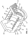
- an internal drum casting hereinafter "internal drum” 80, having, inter alia , reduced weight, increased stiffness, and reduced manufacturing cost.
- the internal drum 80 is provided with a plurality of mounts 82 for mounting the internal drum 80 to a frame structure 84 (FIG. 6) in a manner that substantially reduces any sway of the internal drum 80 within or relative to the frame structure 84.
- the internal drum 80 includes a base portion 86 and an upper structure 88 that are integrally formed in a single casting process from an aluminium alloy or other suitable material.
- This design provides several benefits over previously available two-piece internal drums (e.g., see FIG. 4). For example, by forming the internal drum 80 as a single unit, the amount of machining, finishing work, assembly time, etc., required to produce an internal drum ready for imaging, compared to that required for a two-piece internal drum, is greatly reduced. This reduces the manufacturing time and production cost of the internal drum 80.
- the one-piece design also increases the overall stiffness of the internal drum 80, thereby improving imaging quality.
- the amount of material required to produce the internal drum 80 has been minimised wherever possible to reduce material costs and the weight of the internal drum 80. This is achieved using a unique design methodology wherein a set of strategically positioned and geometrically optimised ribs, supports, and other structures are used in lieu of the more solid and heavy portions of previously available internal drums.
- the amount of material required to produce the internal drum 80, and the weight of the internal drum 80 have also been substantially reduced by mounting the internal drum 80 to the frame structure 84 (Fig. 6) of the imaging system using a plurality of mounts 82 positioned in a plane substantially along the centre of gravity of the internal drum 80.
- the base portion 86 of the internal drum 80 generally has a cylindrical configuration, and includes a cylindrical imaging surface 90 for supporting and positioning a supply of recording media during imaging.
- a plurality of ribs 92 are used to support, strengthen, and stiffen the imaging surface 90.
- the ribs 92 preferably encircle the entire underside of the imaging surface 90, and have a curvature corresponding to the curvature of the imaging surface 90.
- each rib 92 is minimised as much as possible. Additionally, the ribs 92 preferably taper away from the imaging surface 90 to further reduce material requirements and weight.
- the base portion 86 of the internal drum 80 further includes opposing longitudinal members 94 that extend longitudinally along the internal drum 80 between a pair of end supports 96.
- the imaging surface 90 extends between the pair of end supports 96, and is connected to the longitudinal members 94 by a plurality of supports 98, thereby forming a lightweight, strong, honeycomb-type structure.
- the upper structure 88 of the internal drum 80 includes a pair of cross members 100. As illustrated in FIG. 6, the cross members 100 support a rail system 102. The rail system 102 is used to support and guide a movable optical carriage 104 and attached scanning system 106 along the length of the internal drum 80. The material requirements and weight of the cross members 100 are minimised, while maintaining the strength of the cross members 100, by forming the cross members 100 using a plurality of vertical and angled support/brace members 108 (Fig. 5), again forming a lightweight, strong, honeycomb-type structure.
- a plurality of legs 110 of the frame assembly 84 are received within the mounts 82.
- a vibration isolator 112 is positioned between each leg 110 of the frame assembly 84 and a corresponding one of the mounts 82.
- the vibration isolators 112 support and isolate the internal drum 80 against shock and vibration from external sources during the operation, transportation, and storage of the imaging system.
- the mounts 82 are positioned in a horizontal plane 114 substantially along the centre of gravity of the internal drum 80 to minimise the sway of the internal drum 80 within or relative to the frame structure.
- the base portion 86 of the internal drum 80 requires much less material than the base portion 62 of the internal drum 60.
- the reduction in material, which results in a corresponding reduction in the weight of the internal drum 80, is provided, in part, by positioning the mounts 82 in a plane 114 substantially along the centre of gravity of the internal drum 80. By positioning the mounts 82 in this manner, the large, heavy base portion 62 of the internal drum 60 is no longer necessary.
- FIGS. 4 and 6 A further advantage of the one-piece internal drum 80 of the present invention should be readily apparent from a comparison of FIGS. 4 and 6. Specifically, referring first to FIG. 4, a two-piece internal drum 60 requires the use of a mounting system 66 to mount the upper structure 64 onto the base portion 62. Unfortunately, this limits the surface area of the cylindrical imaging surface 22 and the available wrap angle of the imaging beam 28 in the fast scan direction, thereby limiting the imaging speed of the imaging system. When using the one-piece internal drum 80 of the present invention, however, the cylindrical imaging surface 90 may have a substantially larger surface area as indicated in phantom (reference number 116) in FIG. 6. Thus, a substantially larger wrap angle (e.g., 270 degrees) is available during imaging in the internal drum 80, thereby increasing the imaging speed of the imaging system.
- a substantially larger wrap angle e.g., 270 degrees
Landscapes
- Engineering & Computer Science (AREA)
- Multimedia (AREA)
- Signal Processing (AREA)
- Physics & Mathematics (AREA)
- General Physics & Mathematics (AREA)
- Exposure And Positioning Against Photoresist Photosensitive Materials (AREA)
- Printers Or Recording Devices Using Electromagnetic And Radiation Means (AREA)
- Laser Beam Printer (AREA)
- Photoreceptors In Electrophotography (AREA)
- Electronic Switches (AREA)
- Rolling Contact Bearings (AREA)
- Facsimile Scanning Arrangements (AREA)
Abstract
Description
Claims (12)
- An imaging system (10) characterised by:a one-piece internal drum casting (80) including a base portion (86) and an upper structure (88);a cylindrical imaging surface (90) on the base portion (86) of the internal drum casting (80);a frame structure (84); anda mounting system (110, 82, 112) for mounting the internal drum casting (80) to the frame structure (84), the mounting system being in a plane (114) substantially along a centre of gravity of the internal drum casting (80).
- The imaging system (10) according to claim 1, further characterised by:a rail system (102) coupled to the upper structure (88) of the internal drum casting (80);a movable optical carriage (104) supported and guided by the rail system (102); anda scanning system (106) on the movable optical carriage (104) for recording imaging data onto a supply of recording media positioned on the imaging surface (90).
- The imaging system (10) according to any one of the previous claims, wherein the mounting system is further characterised by:at least one mount (82); anda vibration isolator (112) for coupling each mount (82) to the frame structure (84).
- The imaging system (10) according to any one of the previous claims, wherein the internal drum casting (80) includes a plurality of mounts (82) in the plane (114) substantially along the centre of gravity of the internal drum casting (80).
- The imaging system (10) according to any one of the previous claims, wherein the base portion (86) of the internal drum casting (80) is further characterised by a plurality of ribs (92), each of the ribs extending entirely across an underside of the imaging surface (90).
- The imaging system (10) according to claim 5, wherein each of the ribs (92) is tapered.
- A method for manufacturing an internal drum imaging system (10), characterised by:producing a one-piece internal drum (80), having a base portion (86) and an upper structure (88), using a single casting;forming an imaging surface (90) on the base portion of the internal drum; andmounting a movable optical carriage (104) to the upper structure (88) of the internal drum (80).
- The method according to claim 7, further characterised by minimising the weight of the internal drum (80) by forming the base portion (86) and the upper structure (88) of the internal drum using a honeycomb-type structure.
- The method according to any one of claims 7 to 8, further characterised by forming a plurality of ribs (92) on the base portion (86) of the internal drum (80), each of the ribs extending entirely across an underside of the imaging surface (90).
- The method according to claim 9, further characterised by tapering each of the ribs (92).
- The method according to any one of claims 7 to 10, further characterised by mounting the internal drum (80) to a frame structure (84).
- The method according to claim 11, wherein the step of mounting the internal drum to a frame structure is further characterised by providing the internal drum (80) with at least one mount (82), wherein each mount is positioned in a plane (114) substantially along a centre of gravity of the internal drum.
Applications Claiming Priority (2)
| Application Number | Priority Date | Filing Date | Title |
|---|---|---|---|
| US09/229,058 US6184520B1 (en) | 1999-01-12 | 1999-01-12 | Internal drum imaging system |
| US229058 | 1999-01-12 |
Publications (2)
| Publication Number | Publication Date |
|---|---|
| EP1021030A2 true EP1021030A2 (en) | 2000-07-19 |
| EP1021030A3 EP1021030A3 (en) | 2002-01-16 |
Family
ID=22859689
Family Applications (1)
| Application Number | Title | Priority Date | Filing Date |
|---|---|---|---|
| EP00200075A Withdrawn EP1021030A3 (en) | 1999-01-12 | 2000-01-10 | Internal drum imaging system |
Country Status (3)
| Country | Link |
|---|---|
| US (1) | US6184520B1 (en) |
| EP (1) | EP1021030A3 (en) |
| JP (1) | JP2000203089A (en) |
Cited By (2)
| Publication number | Priority date | Publication date | Assignee | Title |
|---|---|---|---|---|
| EP1453295A3 (en) * | 2003-02-28 | 2005-08-24 | Eastman Kodak Company | Vibration isolation system for internal drum scanner |
| EP1231518A3 (en) * | 2001-02-07 | 2006-05-03 | Dainippon Screen Mfg. Co., Ltd. | Image recording apparatus |
Families Citing this family (2)
| Publication number | Priority date | Publication date | Assignee | Title |
|---|---|---|---|---|
| US6772688B2 (en) | 2002-04-05 | 2004-08-10 | Agfa Corporation | Imaging system with automated plate locating mechanism and method for loading printing plate |
| US6729234B2 (en) | 2002-04-05 | 2004-05-04 | Agfa Corporation | Actuation system in an imaging system |
Family Cites Families (7)
| Publication number | Priority date | Publication date | Assignee | Title |
|---|---|---|---|---|
| DE2814612C3 (en) * | 1978-04-05 | 1981-10-15 | Dr. Johannes Heidenhain Gmbh, 8225 Traunreut | Device for setting or measuring angles |
| US5598739A (en) | 1994-01-14 | 1997-02-04 | Miles Inc. | Self-propelled linear motion drive apparatus |
| GB9607450D0 (en) * | 1996-04-10 | 1996-06-12 | Synectix Ltd | Internal drum plate setters |
| US5841567A (en) * | 1996-07-02 | 1998-11-24 | Barco Gerber Systems | Method and apparatus for imaging at a plurality of wavelengths |
| IL118808A0 (en) * | 1996-07-07 | 1996-10-31 | Scitex Corp Ltd | Internal rotating drum plotter |
| US7297219B1 (en) * | 1997-04-18 | 2007-11-20 | Gerber Systems Corporation | Drum assembly for an internal drum imaging device |
| JP2905764B2 (en) * | 1997-11-20 | 1999-06-14 | 株式会社金田機械製作所 | Printing plate exposure equipment using image transformation |
-
1999
- 1999-01-12 US US09/229,058 patent/US6184520B1/en not_active Expired - Fee Related
- 1999-12-27 JP JP37023299A patent/JP2000203089A/en active Pending
-
2000
- 2000-01-10 EP EP00200075A patent/EP1021030A3/en not_active Withdrawn
Cited By (2)
| Publication number | Priority date | Publication date | Assignee | Title |
|---|---|---|---|---|
| EP1231518A3 (en) * | 2001-02-07 | 2006-05-03 | Dainippon Screen Mfg. Co., Ltd. | Image recording apparatus |
| EP1453295A3 (en) * | 2003-02-28 | 2005-08-24 | Eastman Kodak Company | Vibration isolation system for internal drum scanner |
Also Published As
| Publication number | Publication date |
|---|---|
| US6184520B1 (en) | 2001-02-06 |
| EP1021030A3 (en) | 2002-01-16 |
| JP2000203089A (en) | 2000-07-25 |
Similar Documents
| Publication | Publication Date | Title |
|---|---|---|
| US5923473A (en) | Multi-size spot beam imaging system and method | |
| US6184520B1 (en) | Internal drum imaging system | |
| US6250221B1 (en) | Imaging system having external drum and method for producing drum | |
| US5877884A (en) | Light scanning device | |
| EP0373262B1 (en) | Image-reproducing apparatus | |
| JP2001281587A (en) | Holding structure of light source part for optical scanner | |
| US6483530B2 (en) | Cast honeycomb structure with integral damping for ROS platform | |
| JPH06109998A (en) | Light beam recording device | |
| US6081364A (en) | Laser light source for emitting a plurality of laser beams, method adjusting focusing of the laser light source, and scanning optical system | |
| JPH10213768A (en) | Optical scanner | |
| US6052142A (en) | Precision assembly technique using alignment fixture and the resulting assembly | |
| US5173798A (en) | Beam scanning apparatus with sensor for detecting beam position | |
| JP3485760B2 (en) | Scanner lock mechanism | |
| JP2001235699A (en) | Optical scanning device and image forming apparatus using the same | |
| JPH1172728A (en) | Multi-beam deflection scanner | |
| EP0982142B1 (en) | Method and apparatus to provide a loading force for print-head adjustment using magnets | |
| US5212523A (en) | Image read device with reduced mirror vibration | |
| US20060126146A1 (en) | Light beam deflector | |
| US6422100B1 (en) | Independently-tensioned multiple-cable translation system | |
| JP2001027736A (en) | Scanning optical device | |
| JP3542464B2 (en) | Deflection scanning device and image forming apparatus equipped with the same | |
| US5959657A (en) | Method and apparatus for shielding light in an internal drum imaging system | |
| JPH1010448A (en) | Optical scanning device | |
| US6735003B1 (en) | Method and apparatus for reducing artifacts in an imaging system | |
| US20040169719A1 (en) | Vibration isolation system |
Legal Events
| Date | Code | Title | Description |
|---|---|---|---|
| PUAI | Public reference made under article 153(3) epc to a published international application that has entered the european phase |
Free format text: ORIGINAL CODE: 0009012 |
|
| AK | Designated contracting states |
Kind code of ref document: A2 Designated state(s): DE FR GB |
|
| AX | Request for extension of the european patent |
Free format text: AL;LT;LV;MK;RO;SI |
|
| PUAL | Search report despatched |
Free format text: ORIGINAL CODE: 0009013 |
|
| AK | Designated contracting states |
Kind code of ref document: A3 Designated state(s): DE FR GB |
|
| AX | Request for extension of the european patent |
Free format text: AL;LT;LV;MK;RO;SI |
|
| 17P | Request for examination filed |
Effective date: 20020716 |
|
| AKX | Designation fees paid |
Free format text: DE FR GB |
|
| 17Q | First examination report despatched |
Effective date: 20021203 |
|
| STAA | Information on the status of an ep patent application or granted ep patent |
Free format text: STATUS: THE APPLICATION IS DEEMED TO BE WITHDRAWN |
|
| 18D | Application deemed to be withdrawn |
Effective date: 20040615 |