EP1020944A2 - Lithium secondary battery, and process for producing the same - Google Patents
Lithium secondary battery, and process for producing the same Download PDFInfo
- Publication number
- EP1020944A2 EP1020944A2 EP00100127A EP00100127A EP1020944A2 EP 1020944 A2 EP1020944 A2 EP 1020944A2 EP 00100127 A EP00100127 A EP 00100127A EP 00100127 A EP00100127 A EP 00100127A EP 1020944 A2 EP1020944 A2 EP 1020944A2
- Authority
- EP
- European Patent Office
- Prior art keywords
- negative electrode
- particles
- carbonaceous material
- lithium
- battery
- Prior art date
- Legal status (The legal status is an assumption and is not a legal conclusion. Google has not performed a legal analysis and makes no representation as to the accuracy of the status listed.)
- Granted
Links
Images


Classifications
-
- H—ELECTRICITY
- H01—ELECTRIC ELEMENTS
- H01M—PROCESSES OR MEANS, e.g. BATTERIES, FOR THE DIRECT CONVERSION OF CHEMICAL ENERGY INTO ELECTRICAL ENERGY
- H01M4/00—Electrodes
- H01M4/02—Electrodes composed of, or comprising, active material
- H01M4/36—Selection of substances as active materials, active masses, active liquids
- H01M4/38—Selection of substances as active materials, active masses, active liquids of elements or alloys
-
- H—ELECTRICITY
- H01—ELECTRIC ELEMENTS
- H01M—PROCESSES OR MEANS, e.g. BATTERIES, FOR THE DIRECT CONVERSION OF CHEMICAL ENERGY INTO ELECTRICAL ENERGY
- H01M10/00—Secondary cells; Manufacture thereof
- H01M10/05—Accumulators with non-aqueous electrolyte
- H01M10/058—Construction or manufacture
-
- H—ELECTRICITY
- H01—ELECTRIC ELEMENTS
- H01M—PROCESSES OR MEANS, e.g. BATTERIES, FOR THE DIRECT CONVERSION OF CHEMICAL ENERGY INTO ELECTRICAL ENERGY
- H01M10/00—Secondary cells; Manufacture thereof
- H01M10/05—Accumulators with non-aqueous electrolyte
- H01M10/052—Li-accumulators
-
- H—ELECTRICITY
- H01—ELECTRIC ELEMENTS
- H01M—PROCESSES OR MEANS, e.g. BATTERIES, FOR THE DIRECT CONVERSION OF CHEMICAL ENERGY INTO ELECTRICAL ENERGY
- H01M10/00—Secondary cells; Manufacture thereof
- H01M10/05—Accumulators with non-aqueous electrolyte
- H01M10/052—Li-accumulators
- H01M10/0525—Rocking-chair batteries, i.e. batteries with lithium insertion or intercalation in both electrodes; Lithium-ion batteries
-
- H—ELECTRICITY
- H01—ELECTRIC ELEMENTS
- H01M—PROCESSES OR MEANS, e.g. BATTERIES, FOR THE DIRECT CONVERSION OF CHEMICAL ENERGY INTO ELECTRICAL ENERGY
- H01M4/00—Electrodes
- H01M4/02—Electrodes composed of, or comprising, active material
- H01M4/13—Electrodes for accumulators with non-aqueous electrolyte, e.g. for lithium-accumulators; Processes of manufacture thereof
-
- H—ELECTRICITY
- H01—ELECTRIC ELEMENTS
- H01M—PROCESSES OR MEANS, e.g. BATTERIES, FOR THE DIRECT CONVERSION OF CHEMICAL ENERGY INTO ELECTRICAL ENERGY
- H01M4/00—Electrodes
- H01M4/02—Electrodes composed of, or comprising, active material
- H01M4/13—Electrodes for accumulators with non-aqueous electrolyte, e.g. for lithium-accumulators; Processes of manufacture thereof
- H01M4/133—Electrodes based on carbonaceous material, e.g. graphite-intercalation compounds or CFx
-
- H—ELECTRICITY
- H01—ELECTRIC ELEMENTS
- H01M—PROCESSES OR MEANS, e.g. BATTERIES, FOR THE DIRECT CONVERSION OF CHEMICAL ENERGY INTO ELECTRICAL ENERGY
- H01M4/00—Electrodes
- H01M4/02—Electrodes composed of, or comprising, active material
- H01M4/36—Selection of substances as active materials, active masses, active liquids
-
- H—ELECTRICITY
- H01—ELECTRIC ELEMENTS
- H01M—PROCESSES OR MEANS, e.g. BATTERIES, FOR THE DIRECT CONVERSION OF CHEMICAL ENERGY INTO ELECTRICAL ENERGY
- H01M4/00—Electrodes
- H01M4/02—Electrodes composed of, or comprising, active material
- H01M4/36—Selection of substances as active materials, active masses, active liquids
- H01M4/362—Composites
-
- H—ELECTRICITY
- H01—ELECTRIC ELEMENTS
- H01M—PROCESSES OR MEANS, e.g. BATTERIES, FOR THE DIRECT CONVERSION OF CHEMICAL ENERGY INTO ELECTRICAL ENERGY
- H01M4/00—Electrodes
- H01M4/02—Electrodes composed of, or comprising, active material
- H01M4/36—Selection of substances as active materials, active masses, active liquids
- H01M4/362—Composites
- H01M4/364—Composites as mixtures
-
- H—ELECTRICITY
- H01—ELECTRIC ELEMENTS
- H01M—PROCESSES OR MEANS, e.g. BATTERIES, FOR THE DIRECT CONVERSION OF CHEMICAL ENERGY INTO ELECTRICAL ENERGY
- H01M4/00—Electrodes
- H01M4/02—Electrodes composed of, or comprising, active material
- H01M4/36—Selection of substances as active materials, active masses, active liquids
- H01M4/38—Selection of substances as active materials, active masses, active liquids of elements or alloys
- H01M4/386—Silicon or alloys based on silicon
-
- H—ELECTRICITY
- H01—ELECTRIC ELEMENTS
- H01M—PROCESSES OR MEANS, e.g. BATTERIES, FOR THE DIRECT CONVERSION OF CHEMICAL ENERGY INTO ELECTRICAL ENERGY
- H01M4/00—Electrodes
- H01M4/02—Electrodes composed of, or comprising, active material
- H01M4/36—Selection of substances as active materials, active masses, active liquids
- H01M4/58—Selection of substances as active materials, active masses, active liquids of inorganic compounds other than oxides or hydroxides, e.g. sulfides, selenides, tellurides, halogenides or LiCoFy; of polyanionic structures, e.g. phosphates, silicates or borates
- H01M4/583—Carbonaceous material, e.g. graphite-intercalation compounds or CFx
-
- H—ELECTRICITY
- H01—ELECTRIC ELEMENTS
- H01M—PROCESSES OR MEANS, e.g. BATTERIES, FOR THE DIRECT CONVERSION OF CHEMICAL ENERGY INTO ELECTRICAL ENERGY
- H01M4/00—Electrodes
- H01M4/02—Electrodes composed of, or comprising, active material
- H01M4/36—Selection of substances as active materials, active masses, active liquids
- H01M4/58—Selection of substances as active materials, active masses, active liquids of inorganic compounds other than oxides or hydroxides, e.g. sulfides, selenides, tellurides, halogenides or LiCoFy; of polyanionic structures, e.g. phosphates, silicates or borates
- H01M4/583—Carbonaceous material, e.g. graphite-intercalation compounds or CFx
- H01M4/587—Carbonaceous material, e.g. graphite-intercalation compounds or CFx for inserting or intercalating light metals
-
- H—ELECTRICITY
- H01—ELECTRIC ELEMENTS
- H01M—PROCESSES OR MEANS, e.g. BATTERIES, FOR THE DIRECT CONVERSION OF CHEMICAL ENERGY INTO ELECTRICAL ENERGY
- H01M10/00—Secondary cells; Manufacture thereof
- H01M10/05—Accumulators with non-aqueous electrolyte
- H01M10/056—Accumulators with non-aqueous electrolyte characterised by the materials used as electrolytes, e.g. mixed inorganic/organic electrolytes
- H01M10/0564—Accumulators with non-aqueous electrolyte characterised by the materials used as electrolytes, e.g. mixed inorganic/organic electrolytes the electrolyte being constituted of organic materials only
- H01M10/0565—Polymeric materials, e.g. gel-type or solid-type
-
- H—ELECTRICITY
- H01—ELECTRIC ELEMENTS
- H01M—PROCESSES OR MEANS, e.g. BATTERIES, FOR THE DIRECT CONVERSION OF CHEMICAL ENERGY INTO ELECTRICAL ENERGY
- H01M4/00—Electrodes
- H01M4/02—Electrodes composed of, or comprising, active material
- H01M2004/026—Electrodes composed of, or comprising, active material characterised by the polarity
- H01M2004/027—Negative electrodes
-
- H—ELECTRICITY
- H01—ELECTRIC ELEMENTS
- H01M—PROCESSES OR MEANS, e.g. BATTERIES, FOR THE DIRECT CONVERSION OF CHEMICAL ENERGY INTO ELECTRICAL ENERGY
- H01M4/00—Electrodes
- H01M4/02—Electrodes composed of, or comprising, active material
- H01M4/36—Selection of substances as active materials, active masses, active liquids
- H01M4/38—Selection of substances as active materials, active masses, active liquids of elements or alloys
- H01M4/40—Alloys based on alkali metals
- H01M4/405—Alloys based on lithium
-
- H—ELECTRICITY
- H01—ELECTRIC ELEMENTS
- H01M—PROCESSES OR MEANS, e.g. BATTERIES, FOR THE DIRECT CONVERSION OF CHEMICAL ENERGY INTO ELECTRICAL ENERGY
- H01M50/00—Constructional details or processes of manufacture of the non-active parts of electrochemical cells other than fuel cells, e.g. hybrid cells
- H01M50/30—Arrangements for facilitating escape of gases
-
- Y—GENERAL TAGGING OF NEW TECHNOLOGICAL DEVELOPMENTS; GENERAL TAGGING OF CROSS-SECTIONAL TECHNOLOGIES SPANNING OVER SEVERAL SECTIONS OF THE IPC; TECHNICAL SUBJECTS COVERED BY FORMER USPC CROSS-REFERENCE ART COLLECTIONS [XRACs] AND DIGESTS
- Y02—TECHNOLOGIES OR APPLICATIONS FOR MITIGATION OR ADAPTATION AGAINST CLIMATE CHANGE
- Y02E—REDUCTION OF GREENHOUSE GAS [GHG] EMISSIONS, RELATED TO ENERGY GENERATION, TRANSMISSION OR DISTRIBUTION
- Y02E60/00—Enabling technologies; Technologies with a potential or indirect contribution to GHG emissions mitigation
- Y02E60/10—Energy storage using batteries
Definitions
- the present invention relates to a secondary battery using a non-aqueous electrolytic solution, and particularly to a lithium secondary battery having distinguished charging/discharging characteristics such as a higher voltage, a higher energy density, a higher charging/discharging capacity and a longer cycle life as well as a higher safety.
- a lithium secondary battery is now regarded as a promising candidate.
- Lithium secondary battery has a high voltage and a high energy density and also a light weight, as compared with a nickel-cadmium battery, a lead storage battery and a nickel-hydrogen battery.
- a lithium secondary battery using lithium metal as a negative electrode-active material has problems of short battery life and poor safety because lithium tends to deposit on the negative electrode surface as dendrites, resulting in occurrence of an internal short-circuit to the positive electrode and inactivation toward the electrolytic solution.
- lithium secondary batteries using lithium alloys such as Li-Pb, Li-Al, etc. as negative electrode-active materials have been developed.
- lithium alloys such as Li-Pb, Li-Al, etc.
- these lithium secondary batteries still suffer from problems of dendrite deposition and pulverization, so that no satisfactory battery life has been obtained yet.
- a lithium secondary battery using graphite as a negative electrode-active material has been developed and is now in practical use, where the graphite can store/discharge lithium ions by reaction of diffusing lithium ions into between the c planes of graphite or releasing therefrom, while it is more stable than the chemically active metallic lithium and is free from deposition of lithium dendrites, resulting in prolonged cycle life and increased safety.
- the discharge capacity is 370 Ah/kg at most.
- the negative electrode-active materials of higher capacity include Al, Pb, etc., i.e. elements capable of forming intermetallic compounds with Li, but suffer from a rapid cycle deterioration when used alone or in combination with electroconductive particles as a negative electrode-active material, and thus have not been practically used as a negative electrode-active material.
- Japanese Patent Nos. 2948205 and 2948206 disclose negative electrode materials containing 30 to 90% by weight of silicon. But since silicon is simply mixed with a carbonaceous material and sintered at 600 to 1400°C under non-oxidative atmosphere, uniformity of the quality of the negative electrode materials and improvement of the quality thereof cannot be expected.
- An object of the present invention is to provide a lithium secondary battery with a higher capacity and a longer cycle life and a process for producing the same.
- a lithium secondary battery which comprises a positive electrode, a negative electrode containing a lithium ion-storable/dischargeable negative electrode-active material and a lithium ion conductive, non-aqueous electrolytic solution or polymer electrolyte, the negative electrode-active material containing a carbonaceous material and particles comprising at least one of elements capable of forming a compound with lithium, the elements having a melting point of at least 900°C and a thermal expansion coefficient of not more than 9 ppm/K at room temperature (25°C), the particles being embedded in a plurality of layers of the carbonaceous materials, and the particles together with a carbonaceous material being subjected to a mechanical treatment to make size reduction in advance; a method for using the same in an electric car as a battery assembly; and a process for producing the same.
- Element capable of forming a compound with lithium is at least one element selected from Si, Ge and Pt, preferably from Si and Ge.
- the term "mechanically treating” means repeating crushing and pressure welding, more concretely, conducting crushing, etc. using a conventional ball mill, a planet type ball mill, an attritor, etc.
- particles of an element such as Si, Ge, or the like and a carbonaceous material (A) are placed in a ball mill, and mechanical treatment is conducted until initial mean particle size of Si or Ge particles becomes preferably 1/2 or less, more preferably 1/5 or less, most preferably 1/10 or less.
- the mechanical treatment such as crushing is conducted until the particle size becomes preferably 20 ⁇ m or less, more preferably 5 ⁇ m or less, most preferably 1 ⁇ m or less.
- heat treatment can be conducted or not conducted.
- the carbonaceous material (B) used in the step (b) there can be use a carbon precursor such as tar.
- the carbonization (or carbonization heat treatment) in the step (c) can be carried out at preferably 800 to 1500°C, more preferably 900 to 1300°C.
- the carbon precursor becomes the carbonaceous material (B) by the above-mentioned carbonization heat treatment.
- An electric car with a high voltage and good mileage per one charging can be provided by mounting a battery assembly consisting of the present lithium secondary batteries on the electric car.
- the present lithium secondary battery can be used also as a battery for hybrid cars.
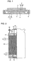
- Fig. 1 shows the basic structure of a coin type lithium secondary battery according to one embodiment of the present invention.
- a positive electrode 2 comprising a positive electrode current collector 2a and a positive electrode mix 2b is mounted on a positive electrode can 1 by welding, whereas a negative electrode 4 comprising a negative electrode current collector 4a and a negative electrode mix 4b is mounted on a negative electrode can 3 by welding.
- Both the positive electrode and the negative electrode are impregnated with an electrolytic solution containing an electrolyte (e.g. LiPF 6 ) dissolved in a solvent mixture of e.g.
- an electrolyte e.g. LiPF 6
- EC ethylene carbonate
- DMC dimethyl carbonate
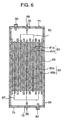
- Fig. 2 shows the basic structure of a cylindrical lithium secondary battery.
- An electrode assembly comprises a positive electrode 13 comprising a positive electrode current collector 11 coated with a positive electrode mix 12, a negative electrode 16 comprising a negative electrode current collector 14 coated with a negative electrode mix 15, and a separator 17.
- the positive electrode 13, the separator 17, the negative electrode 16 and the separator 17 are laminated in this order and coiled as shown in Fig. 3.
- a positive electrode tab 18 and a negative electrode tab 19 are connected to the positive electrode 13 and the negative electrode 18 of the electrode assembly, respectively.
- the electrode assembly is encased in a battery can 20, where the negative electrode tab 19 is connected to the battery can 20, whereas the positive electrode tab 18 is connected to a battery lid 21.
- the battery lid 21 is fixed to the battery can 20 through an insulating gasket 22 to tightly seal the electrode assembly and the inside of the battery can 20.
- an insulating plate 23 is also provided.
- An electrolytic solution containing Li ions is contained in the tightly sealed battery can. No positive electrode mix is applied to both edge parts of the positive electrode to expose a metallic foil. The positive electrode tab is connected to one of the edge parts.
- Figs. 4A and Fig. 4B show a top view and a cross-sectional view of a square type lithium secondary battery according to the present invention, respectively.
- a square type lithium secondary battery comprises an electrode assembly comprising positive electrode 31 and negative electrode 32 as alternately laminated in a separator 33 and inserted into a battery can 34 made from, e.g. aluminum.
- Positive electrode leads 35 and negative electrode leads 37 welded to the tops of the respective corresponding electrodes are connected to a positive electrode terminal 38 and a negative electrode terminal 39, respectively.
- the positive electrode terminal 38 and the negative electrode terminal 39 are inserted into a battery lid 41 through packings 40.
- An external cable and the battery can be connected to each other by nuts 50 provided at the positive electrode terminal 38 and the negative electrode terminal 39, respectively.
- the battery lid 41 is provided with a safety valve for discharging a gas accumulated in the battery when the pressure in the battery elevates, and an electrolyte solution inlet.
- the safety valve comprises a gas discharge outlet port 42, an O-ring 43 and a sealing bolt 44.
- the electrolytic solution inlet comprises an inlet port 45, an O-ring 46 and a sealing bolt 47. After laser welding of the battery can 34 to the battery lid 41, an electrolytic solution is introduced therein through the inlet port 45 and then the inlet port 45 is tightly closed by the sealing bolt 47, thereby completing the square type lithium secondary battery.
- Fig. 5 shows a battery assembly of said square type lithium secondary batteries as connected to one another in series.
- a battery assembly of 8 batteries as connected to one another in series is made up by arranging the batteries in a row so that their sides can be counterposed to one another, while keeping the battery lids 41 of the square type lithium secondary batteries 51 upward.
- Two spacers 52 are inserted between the adjacent counterposed sides of batteries 51 along the height direction.
- Stainless steel metal plates 53 and fixing parts 58 fixed to the front and the back, and the sides of the battery assembly, respectively, are set and secured by bolts 59 so as to apply an inward pressure to the batteries 51.
- a rib-formed projection 60 is formed on each of the stainless steel metal plates 53.
- Positive electrode terminals and negative electrode terminals on the respective square type batteries 51 are connected by electric cables so as to bring all the batteries into series connection with further connection to a positive electrode terminal 54 and a negative electrode terminal 55 of the battery assembly, respectively.
- the positive electrode terminals and the negative electrode terminals of the respective batteries 51 are connected to a control circuit substrate 56 through a positive electrode voltage input cable and a negative electrode voltage input cable, respectively, and the voltage and the currents of the respective batteries are measured for charge/discharge control of the battery assembly.
- the control circuit substrate 56 is provided with a microcomputer so as to have a function of stopping the charging/discharging of the battery assembly when one of the voltage and the current of at least one of batteries 51 comes off a given range.
- a thermocouple 57 is provided on the side of battery at the 4th position from the back end to input its temperature signal to the control circuit substrate 56 so as to stop charging/discharging when the battery temperature exceeds a given temperature.
- This embodiment is directed to an electrode assembly of a lamination type of strip electrodes, but the same battery assembly as in this embodiment can be made up from a flat, ellipsoidal coil type.
- the negative electrode-active material must contain particles comprising at least one of elements capable of forming a compound with lithium.
- the element capable of forming a compound with lithium is at least one element selected from Si, Ge and Pt, preferably Si and Ge from the viewpoints of easy handling of powder, a lower production cost, etc.
- the particles can be composed of a simple substance of the element or alloy or intermetallic compound containing the element, or a mixture of particles composed only of simple substances of the elements, so long as they can interstitially diffuse/release lithium ions in an electrochemical manner.
- the average particle size of the particles comprising at least one of elements capable of forming a compound with lithium contained in the negative electrode-active material exceeds 20 ⁇ m, the cycle life of the lithium secondary battery will be considerably shortened.
- the average particle size is smaller, the characteristics of the negative electrode-active material will be improved, but too smaller average particle size gives rise to vigorous oxidation in the atmospheric air, making the operation in the negative electrode preparation step unfavorable.
- the average particle size is preferably in a range of 0.1 to 20 ⁇ m, more preferably in a range of 0.5 to 5 ⁇ m.
- the particles comprising at least one of elements capable of forming a compound with lithium are embedded in or enclosed by the carbonaceous material, where there are particles completely covered with the carbonaceous material on their surfaces and particles partially exposed to the outside from the surrounding carbonaceous material. Though the particles completely covered with the carbonaceous material on the surfaces are preferably, those partially exposed to the outside from the surrounding carbonaceous material can be used as well.
- One particle of the negative electrode-active material contains one or a plurality of the particles comprising the element as embedded in the carbonaceous material. Even the presence of a large number of the particles comprising the element does not cause any problem in the characteristics, so long as they are embedded in the carbonaceous material.
- the foregoing conditions of the negative electrode-active material can be determined by observing the cross-section of the negative electrode-active material by a scanning electron microscope (SEM).
- Particle sizes of particles comprising at least one of elements capable of forming a compound with lithium can be determined a particle size distribution of the particles as observed in the cross-section of the negative electrode-active material, where number of the particles as determined is 500 to 1,500 for each cross-section of negative electrode-active materials. If the presence of carbonaceous material around the particles can be confirmed in the cross-sectional observation of the negative electrode-active material, it can be concluded that said particles are embedded in the carbonaceous material.
- Content ratio by weight of the particles to the negative electrode-active material containing the particles as embedded in the carbonaceous material is preferably 0.01 to 0.8, more preferably 0.03 to 0.7, most preferably 0.05 to 0.5, particularly preferably 0.05 to 0.3.
- Carbonaceous material (A) containing the particles as embedded therein must contain a crystalline carbon region.
- the carbonaceous material (A) is amorphous carbon, it is inferior to the crystalline carbon in the charging/discharging characteristics.
- the carbonaceous material (A) has a smaller d (002) interplanar spacing than that of carbonaceous material (B). This means that the carbonaceous material (A) has a higher degree of crystallinity than that of carbonaceous material (B).
- the d (002) interplanar spacing of carbonaceous material (A) is preferably 0.335 nm to 0.345 nm, more preferably 0.335 nm to 0.340 nm, particularly preferably 0.335 nm to 0.338 nm.
- X-ray diffraction method using X-rays based on CuK ⁇ beam at a tube voltage of 50 kV and a tube current of 250 mA with steps of 0.002 to 0.01 deg. is used for the determination.
- Diffraction curves corresponding to diffraction for the d(002) plane interplanar spacing are smoothed, while eliminating the background, thereby obtaining a substantial d(002) diffraction calibration curve. Peak of the calibration curve can be represented by 2 ⁇ , where ⁇ is a diffraction angle of the (002) plane.
- the carbonaceous material (B) is harder than the carbonaceous material (A).
- the carbonaceous material (B) is harder than the carbonaceous material (A).
- it seems necessary to maintain the shape of the negative electrode-active material by selecting a larder carbonaceous material (B) for the external material and to lessen the strains due to expansion/contraction of particles comprising at least one of elements capable of forming a compound with lithium by selecting a softer carbonaceous material (A) as the internal material.
- Hardness of carbonaceous materials is determined by a micro-Vickers hardness tester having a nano-indentation function. At first, a carbonaceous material for embedding particles comprising at least one of elements capable of forming a compound with lithium is embedded in a resin, and then a smooth cross-section is made to expose by mechanical grinding. Then, a desired position of carbonaceous material is tested by the micro-Vickers hardness tester with a pyramid indenter under a load of 0.5 to 5 g.
- a hardness ratio of the external carbonaceous material to the carbonaceous material near the particles comprising at least one of elements capable of forming a compound with lithium can vary in an appropriate range, depending upon combinations of carbonaceous material (A) with carbonaceous material (B).
- the hardness ratio of (B) to (A) is preferably not less than 1.1, more preferably not less than 1.1, most preferably 1.2 to 10.0, particularly 1.5 to 5.0.
- Degree of crystallinity of carbonaceous material can be evaluated by Raman spectral distribution using an argon laser with a wavelength of 0.5145 nm. Peaks at about 1580 cm -1 correspond to a crystal structure of lamination-formed c planes, while peaks at about 1360 cm -1 correspond to a disturbed amorphous structure. The peaks at about 1580 cm -1 refer to peaks in a range of 1570 to 1620 cm -1 , whereas the peaks at about 1360 cm -1 refer to peaks in a range of 1350 to 1370 cm -1 .
- the degree of crystallinity of carbonaceous material (B) can be determined by measuring an argon laser Raman spectrum before and after the coating treatment with the carbonaceous material (B). When R value is higher after the coating treatment with the carbonaceous material (B) than the R value before the coating treatment, the carbonaceous material (B) is composed of amorphous carbon.
- Carbonaceous material can be formed by carbonizing a carbon precursor as well.
- Carbon precursor for use in the present invention includes, for example, easily graphitizable precursors such as petroleum pitch, coal pitch, etc., and non-graphitizable precursors such as isotropic pitch, polyacrylonitrile, phenol resin, furan resin, etc., but the easily graphitizable precursors are preferable for formation of carbonaceous material (A).
- Carbonization temperature of carbon precursor is 800° to 1,500°C, preferably 900° to 1,200°C, because the particles comprising at least one of elements capable of forming a compound with lithium will be formed into carbides or melted at higher temperatures. Carbonization is carried out preferably in such an atmosphere as an inert gas or a nitrogen gas.
- Carbonaceous particles can be formed into carbonaceous material in such a state as to bond the particles comprising at least one of elements capable of forming a compound with lithium by mechanical pressure welding.
- crystalline carbon and amorphous carbon can be used, but crystalline carbon is preferable.
- the apparatus for this purpose includes, for example, a planetary type ball will capable of giving mechanical pressure welding when balls collide with one another or with the vessel wall, an apparatus capable of giving mechanical pressure welding between the vessel and the pressure welding spatula provided at a given distance, etc.
- the carbonaceous particles and particles comprising at least one of elements capable of forming a compound with lithium can be subjected to repetitions of mechanical pressure welding, thereby embedding the latter particles into the resulting carbonaceous material.
- the carbonaceous material formed on the particles comprising at least one of elements capable of forming a compound with lithium by said mechanical pressure welding has an increased specific surface area, but maintains the physical properties of the original carbonaceous particles to some extent. Particularly in case of carbonaceous particles with smaller particle sizes and larger specific surface area, no negative electrode-active material having desired physical properties can be obtained and thus the carbonaceous particles must have a specific surface area of preferably not more than 100 m 2 /g, more preferably 0.5 to 50 m 2 /g.
- said carbonaceous particles has a d (002) interplanar spacing of preferably 0.335 nm to 0.345 nm, more preferably 0.335 nm to 0.340 nm, most preferably 0.335 nm to 0.337 nm.
- Heat treatment is not always necessary after the mechanical pressure welding, but it is preferable to conduct heat treatment at 200° to 1,200°C, particularly 900° to 1,100°C.
- Heat treatment atmosphere can be an inert gas, a nitrogen gas or in vacuum, so long as it can prevent any oxidation.
- easily graphitizable precursor or non-graphitizable precursor can be used for the formation of carbonaceous material (B).
- easily graphitizable precursor is preferable.
- the negative electrode-active material must have a specific surface area of preferably 1 to 100 m 2 /g, more preferably 2 to 50 m 2 /g.
- the carbonaceous material must have a d002 interplanar spacing of preferably 0.335 nm to 0.345 nm, more preferably 0.335 nm to 0.340 nm, most preferably 0.335 nm to 0.337 nm.
- Positive electrode-active material for use in the present invention includes composite oxides such as lithium cobalt oxide (Li x CoO 2 ), lithium nickel oxide (Li x NiO 2 ), Lithium manganese oxide (Li x Mn 2 O 4 , Li x MnO 3 ), lithium nickel cobalt oxide (Li x Ni y Co (1-y) O 2 ), etc., where o ⁇ x ⁇ 1.2 and o ⁇ y ⁇ 1. In other words, they are stoichiometric compositions, but may be oxides slightly deviated from the stoichiometric compositions. These materials have an average particle size of preferably 3 to 40 ⁇ m.
- Electrolytic solution for use in the present invention includes a solution of a lithium salt as an electrolyte in an organic solvent.
- the organic solvent includes, for example, butylene carbonate, propylene carbonate, diethyl carbonate, ethyl methyl carbonate, ethylene carbonate, dimethyl carbonate, methyl carbonate, 1,2-dimethoxyethane, 1,2-diethoxyethane, ethoxymethoxyethane, ⁇ -butyrolactone, ⁇ -valerolactone, dipropyl carbonate, tetrahydrofuran, 2-methyltetrahydrofuran, dioxane, dimethyl sulfoxide, sulfolane, methylsulfolane, acetonitrile, methyl acetate, methyl formate, etc., or solvent mixtures of at least two thereof.
- Electrolyte for use in the present invention include lithium salts such as lithium hexafluorophosphate (LiPF 6 ), lithium borofluoride (LiBF 4 ), lithium perchlorate (LiClO 4 ), lithium bis(trifluoromethylsulfonyl)imide (LiN(CF 2 SO 2 ) 2 ), arsenic lithium hexafluoride (LiAsF 6 ), lithium trifluorometasulfonate (LiCF 2 SO 3 ), etc.
- lithium salts such as lithium hexafluorophosphate (LiPF 6 ), lithium borofluoride (LiBF 4 ), lithium perchlorate (LiClO 4 ), lithium bis(trifluoromethylsulfonyl)imide (LiN(CF 2 SO 2 ) 2 ), arsenic lithium hexafluoride (LiAsF 6 ), lithium trifluorometasulfonate (LiCF
- lithium hexafluorophosphate LiPF 6
- lithium borofluoride LiBF 4
- lithium perchlorate LiClO 4
- lithium bis(trifluoromethylsulfonyl)imide LiN(CF 2 SO 2 ) 2
- Concentration of dissolved electrolyte in organic solvent is preferably 0.5 to 2.0 moles/l.
- Electroconductive material for the positive electrode and the negative electrode for use in the present invention includes graphite, amorphous carbon an carbon mixture thereof, and has an average particle size of preferably not more than 30 ⁇ m and a specific surface area of preferably 1 to 300 m 2 /g. Carbon short fibers, 5 to 10 ⁇ m in diameter and 10 to 30 ⁇ m long, can be preferably used as well.
- metallic particles with less reactivity toward the electrolytic solution can be used as an electroconductive material as well.
- Ni, Co, Fe, Cu, Ti, Cr and alloys containing these can be used for the negative electrode
- Ni, Co, Fe, Ti, Cr, Al and alloys containing these can be used for the positive electrode.
- These metallic particles are hard to undergo deformation of particles by a press and the coatability will be poorer with increasing particle sizes. Thus, they must have an average particle size of preferably not more than 30 ⁇ m.
- Binder plays a role in connecting an electroconductive material to a current collector.
- Binder for use in the present invention includes such resins as poly(vinylidene fluoride) (PVDF), ethylenepropylenediene copolymer (EPDM), polytetrafluoroethylene (PTFE), polyethylene, polypropylene, polystyrene, polyvinylpyridine, chlorosulfonated polyethylene, latex, etc.
- PVDF poly(vinylidene fluoride)
- EPDM ethylenepropylenediene copolymer
- PTFE polytetrafluoroethylene
- polyethylene polypropylene
- polystyrene polyvinylpyridine
- chlorosulfonated polyethylene latex, etc.
- an amount of the binder is preferably 2 to 20% by weight.
- the amount of the binder for the positive electrode is more preferably 2 to 10% by weight, whereas that for the negative electrode is more preferably 5 to 15% by weight.
- Current collector for use in the negative electrode includes foils and sponge metals of Cu, Ni or stainless steel, whereas that for use in the positive electrode includes foils and sponge metals of Al, Ni or stainless steel.
- a combination of a negative electrode current collector of Cu with a positive electrode current collector of Al is preferable. It is preferable from the viewpoint of high strength that these foils are rolled ones, but electrolytic foils can be used as well.
- the foils have a thickness of preferably not more than 100 ⁇ m, particularly preferably 8 to 40 ⁇ m.
- Separator for use in the present invention includes sheet separators and polymer electrolyte both having a low resistance to the ion conductivity of electrolytic solution, no reactivity toward the electrolytic solution and a distinguished solution retainability.
- the sheet separators for use in the present invention include, for example, porous films of polypropylene, polyethylene, polyolefin, polyester, polytetrafluoroethylene, polyflon, etc. and non-woven fabrics comprising glass fibers and the foregoing polymers. Particularly preferable are porous films of polypropylene, polyethylene and polyolefin.
- Polymer electrolytes for use in the present invention include composites comprising a polymer matrix selected from polyethylene oxide, polypropylene oxide, poly(vinylidene fluoride), polyacrylamide, etc. and said electrolyte as dissolved in the polymer matrix, gel cross-linked matrix further containing a solvent, polymer electrolytes grafted with ionically dissociated groups of low molecular weight polyethylene oxide, crown ether, etc. on the polymer main chain and gel state polymer electrolytes comprising a high molecular weight polymer containing said electrolyte therein.
- the present lithium secondary battery comprises an electrode assembly formed by lamination from a positive electrode comprising a positive electrode-active material, a positive electrode electroconductive material, a binder and a positive electrode current collector, a negative electrode comprising a negative electrode-active material, a binder, a negative electrode current collector or further a negative electrode electroconductive material, and a separator inserted between the positive electrode and the negative electrode; an electrolytic solution; and a battery container for tightly enclosing the electrode assembly and the electrolytic solution, as connected to the electrode assembly.
- the electrode assembly can be in a lamination structure of the positive electrode, the separator and the negative electrode, with tabs stuck out from the respective electrodes, or a laminate-coiled structure of the respective electrodes in a tab-connected strip form, or a laminate-wound and subsequently flattened structure of the respective electrodes in a tab-fixed strip form.
- any structure can be used, so long as the battery has an electrode assembly with a separator inserted between the counterposed positive and negative electrodes.
- the present lithium secondary battery based on a non-aqueous electrolytic solution has a higher capacity and a longer life than those of the conventional lithium secondary battery.
- the present lithium secondary battery can be used for various portable electronic appliances, particularly notebook-type personal computers, notebook-type word processors, palm-top (pocket) personal computers, portable telephones, PHS, portable facsimiles, portable printers, headphone stereos, video cameras, portable television receivers, portable CD players, portable MD players, electric shavers, electronic notebooks, transceivers, electric tools, radios, tape recorders, digital cameras, portable copiers, portable video games, etc., or further can be used as secondary batteries for electric cars, hybrid cars, automatic ventors, electric carts, road levelling battery systems, household batteries, spread-type power storing systems (encased in installation-type electric appliances), emergency power supply system, etc.
- Silicon particles having an average particle size of 10 ⁇ m and graphite particles having an average particle size of 20 ⁇ m were joined together in a ratio of 50:50 by weight and subjected to a ball mill treatment based on repetitions of mechanical pressure welding using a planetary ball mill for 24 hours.
- Ball mill vessel and balls were made from stainless steel, and the powder preparation and the ball mill treatment were carried out an Ar atmosphere.
- the composite material, petroleum pitch and tetrahydrofuran were mixed together in a ratio of 100:70:500 by weight are stirred under reflux for one hour. Tetrahydrofuran was removed therefrom in a rotary evaporator, followed by vacuum drying at 150°C for 3 hours, whereby Si-C composite power/pitch composite material was obtained. Then, the composite material was disintegrated to 200-mesh and under in a cutter mill, heated up to 250°C in air at a rate of 3°C/min and kept at that temperature for one hour. Then, the resulting product was heated up to 1,000°C in a nitrogen gas stream at a rate of 20°C/h and kept at that temperature for one hour, thereby carbonizing the petroleum pitch.
- the resulting product was disintegrated to 200-mesh and under in a cutter mill, whereby silicon-carbon composite powder was obtained.
- X-ray diffraction analysis of the Si-C powder revealed that peaks showing diffractions of carbon and silicon were observed. Diffraction peaks were at d (002) interplanar spacings of 0.3358 nm and 0.3378 nm. It was found that the R value was 0.7 and the specific surface area was 29 m 2 /g.
- the Si-C composite powder was kneaded with a solution of PVDF in N-methylpyrrolidone in a ratio of silicon-carbon composite powder: PVDFF 85:15 by weight and the resulting slurry was applied to a 20 ⁇ m-thick Cu foil, followed by drying at 120°C for one hour, press molding into an electrode by a roller press and ultimately blanking to 20 mm in diameter as a negative electrode.
- Powder of lithium cobalt oxide LiCoO 2 having an average particle size of 10 ⁇ m was used as a positive electrode-active material.
- a ratio of the positive electrode mix to the negative electrode mix by weight was made to be 15 owing to the large negative electrode capacity.
- a coin type battery, as shown in Fig. 1 was made with the negative electrode and the positive electrode to evaluate its characteristics.
- a positive electrode 2 comprising a positive electrode current collector 2a and a positive electrode mix 2b was mounted on a stainless steel positive electrode can 1 by spot welding
- a negative electrode 4 comprising a negative electrode current collector 4a and a negative electrode mix 4b was mounted on a stainless steel negative electrode can 3 by spot welding.
- Both the positive electrode and the negative electrode were impregnated with an electrolytic solution containing 1 mole/l of LiPF 6 dissolved in a 1:2 (by weight) solvent mixture of ethylene carbonate (EC) and dimethyl carbonate (DMC), and then the positive electrode and the negative electrode were counterposed to each other, while interposing a polyethylene separator 5 therebetween, and the positive electrode can and the negative electrode can were fixed to each other by pressure welding through an insulating gasket 6.
- the resulting battery was subjected to a charging/discharging cycle test by charging with a charge current of 1 mA at a charge end voltage of 4.2 V and discharging with a discharge current of 1 mA at a discharge end voltage of 2.7 V.
- the initial discharge capacity of the battery was 10.2 mAh and the irreversible capacity ratio was 12%.
- a discharge capacity maintenance ratio of the 100th cycle to the 1st cycle was found to be 94%.
- a coin type battery was produced, using LiMn 2 O 4 having an average particle size of 10 ⁇ m as a positive electrode material in the same manner as in Example 1.
- the battery was subjected to a charging/discharging cycle test by charging with a charge current of 1 mA at a charge end voltage of 4.3 V and discharging with a discharge current of 1 mA at a discharge end voltage of 2.8 V.
- a charging/discharging cycle test by charging with a charge current of 1 mA at a charge end voltage of 4.3 V and discharging with a discharge current of 1 mA at a discharge end voltage of 2.8 V.
- the initial charge capacity of the battery was 4.5 mAh and a ratio of the irreversible capacity was 10%.
- a discharge capacity maintenance ratio of the 100th cycle to the 1st cycle was found to be 97%.
- Ge particles having an average particle size of 1 ⁇ m, coal pitch and tetrahydrofuran were mixed together in a ratio of 100:100:500 by weight and stirred under reflux for one hour. Tetrahydrofuran was removed therefrom in a rotary evaporator, followed by vacuum drying at 150°C for 3 hours, thereby obtaining a Ge-C composite powder/pitch composite material.
- the composite material was pulverized to 200-mesh and under in a cutter mill, heated up to 250°C in air at a rate of 3°C/min and maintained at that temperature for one hour.
- the resulting product was heated up to 1,200°C in a nitrogen gas stream at a rate of 20°C/hr and maintained at that temperature for one hour, thereby carbonizing the pitch.
- the carbonized product was pulverized to 200-mesh and under in a cutter mill, thereby obtaining a composite material.
- Analysis of the resulting composite material by wide angle X-ray diffraction revealed that peaks showing diffractions of C and Ge were observed.
- the d (002) interplanar spacing of C was found to be 0.3410 nm.
- Average particle size of Ge determined by cross-sectional observation was found to be 3.1 ⁇ m, and the R value was found to be 1.0.
- Said composite material and phenol resin were mixed together in a ratio of 100:100 by weight, followed by vacuum drying at 120°C for 3 hours, thereby obtaining a composite material/resin composite material.
- the resulting composite material was disintegrated to 200-mesh and under in a cutter mill, heated up to 250°C in air at a rate of 3°C/min. and maintained at that temperature for one hour. Then, the resulting product was heated up to 1,000°C in a nitrogen gas stream at a rate of 20°C/hr and maintained at that temperature for one hour, thereby carbonizing the resin. The carbonized product was disintegrated to 200-mesh and under in a cutter mill, thereby obtaining Ge-C composite powder. Analysis of the composite powder by X-ray diffraction revealed that peaks showing diffractions of C and Ge were observed. The d (002) interplanar spacing of C was found to be 0.3450 nm with an R value of 1.5 and a specific surface area of 8 m 2 /g.
- a battery was produced, using the Ge-C composite powder as a negative electrode-active material in the same manner as in Example 1, but an electrolytic solution containing 1.5 moles/l of LiPF 6 dissolved in a 2:3 (by weight) solvent mixture of PC and DM was used for the electrolytic solution.
- the resulting lithium secondary battery was subjected to a charging/discharging cycle test by charging with a charge current of 2 mA at a charge end voltage of 4.2 V and discharging with a discharge current of 2 mA at a discharge end voltage of 2.7 V.
- a discharge capacity maintenance ratio of the 100th cycle to the 1st cycle was found to be 92%.
- Si particles having an average particle size of 10 ⁇ m and graphite particles having an average particle size of 20 ⁇ m were mixed together in a ratio of 80:20 by weight and subjected to a ball mill treatment for 96 hours, where the ball mill vessel and balls were made from stainless steel and the powder preparation and the ball mill treatment were carried out in an Ar atmosphere. Analysis of the resulting Si-C composite powder by wide angle X-ray diffraction revealed that peaks showing diffractions of C and Si were observed.
- the d (002) interplanar spacing of C was found to be 0.3361 nm and the average particle size of Si determined by cross-sectional observation was found to be 0.9 ⁇ m, with an R value of 0.9 and a specific surface area of Si-C composite powder being 280 m 2 /g.
- a battery was produced, using the Si-C composite powder as a negative electrode-active material in the same manner as in Example 1, but an electrolytic solution containing 1.5 moles/l of LiPF 6 in a 1:2 (by weight) solvent mixture of EC and DMC was used for the electrolytic solution.
- the battery was subjected to a charging/discharging cycle test by charging with a charge current of 2 mA at a charge end voltage of 4.2 V and discharging with a discharge current of 2 mA at a discharge end voltage of 2.7 V.
- a charging/discharging cycle test by charging with a charge current of 2 mA at a charge end voltage of 4.2 V and discharging with a discharge current of 2 mA at a discharge end voltage of 2.7 V.
- the initial discharge capacity of the battery was 13.6 mAh and the irreversible capacity was 53%.
- a discharge capacity maintenance ratio of the 100th cycle to the 1st cycle was found to be 23%.
- a cylindrical lithium secondary battery was produced as a lithium secondary battery according to the present invention, and its basic structure is shown in Fig. 2.
- An electrode assembly comprised a positive electrode 13 comprising a positive electrode current collector 11 coated with a positive electrode mix 12, a negative electrode 16 comprising a negative electrode current collector 14 coated with a negative electrode mix 15 and a separator 17.
- the positive electrode 13, the separator 17, the negative electrode 16 and the separator 17 were laminated in this order and coiled as shown in Fig. 3.
- a positive electrode tab 18 and a negative electrode tab 19 were connected to the positive electrode and the negative electrode 16 of the electrode assembly, respectively.
- the electrode assembly was encased in a battery can 20, where the negative electrode tab 19 was connected to the battery can 20, whereas the positive electrode tab 18 was connected to a battery lid 21.
- the battery lid 21 was fixed to the battery can 20 through an insulating gasket 22 to tightly seal the electrode assembly and the inside of the battery can 20.
- an insulating plate 23 was also provided.
- An electrolytic solution containing Li ions was contained in the tightly sealed battery can.
- SUS 304, SUS 316, mild steel with an anticorrosive coating, etc. could be used.
- Lithium cobalt oxide LiCoO 2 having an average particle size of 10 ⁇ m as a positive electrode-active material, scale-form graphite having an average particle size of 5 ⁇ m as a positive electrode electroconductive material, PVDF as a binder and a 20 ⁇ m-thick Al foil as a positive electrode current collector were used.
- a mixture of LiCoO 2 , scale-form graphite and PVDF in a ratio of 88:7:5 by weight was mixed with N-methylpyrrolidone to prepare a slurry of positive electrode mix. The slurry was applied to both sides of the Al foil, followed by vacuum drying at 120°C for one hour and successive press molding into an electrode piece by a roller press.
- Negative electrode-active material was prepared in the following manner. Si particles having an average particle size of 10 ⁇ m and graphite particles having an average particle size of 20 ⁇ m were joined together in a ratio of 80:20 by weight and subjected to a ball mill treatment for 48 hours, where the ball mill vessels and balls were made from stainless steel and the powder preparation and ball mill treatment were carried out in an Ar atmosphere. Analysis of the resulting composite material by wide angle X-ray diffraction revealed than the d (002) interplanar spacing of C was 0.3356 nm. Then, the composite material, petroleum pitch and tetrahydrofuran were mixed together in a ratio of 100:200:700 by weight and stirred under reflux for one hour. Tetrahydrofuran was removed therefrom in a rotary evaporator, followed by vacuum drying at 150°C for 3 hours, thereby obtaining a composite material/pitch composite material.
- the composite material was pulverized to 200-mesh and under in a cutter mill, heated up to 250°C in air at a rate of 3°C/min. and maintained at that temperature for one hour.
- the product was heated up to 1,000°C in a nitrogen gas stream at a rate of 20°C/h and maintained at that temperature for one hour, thereby carbonizing the pitch.
- the carbonized product was disintegrated to 200-mesh and under in a cutter mill, thereby obtaining a Si-C composite powder.
- the Si-C composite powder was used as a negative electrode-active material.
- the negative electrode-active material, scale-form graphite having an average particle size of 10 ⁇ m as a negative electrode electroconductive material, PVDF as a binder and a 20 ⁇ m-thick Cu foil as a negative electrode current collector were used.
- the negative electrode-active material, the scale-form graphite and PVDF were mixed together in a ratio of 60:30:10 by weight together with N-methylpyrrolidone to prepare a slurry of negative electrode mix.
- the slurry was applied to both sides of the Cu foil, followed by vacuum drying at 120°C for one hour and subsequent press molding into an electrode piece by a roller press. Then A negative electrode, 40 mm wide and 290 mm long, was cut of the electrode piece, thereby preparing the negative electrode.
- a ratio of the applied negative electrode mix to the applied positive electrode mix was 1:10 by weight.
- the Cu foil was exposed in 10 mm-long, negative electrode mix-uncoated regions at both edges of the negative electrode, as in the case of the positive electrode.
- a Ni negative electrode tab was pressure welded to one end of the negative electrode by ultrasonic welding.
- a porous polypropylene film 25 ⁇ m thick and 44 mm wide, was used as a separator.
- electrolytic solution a solution containing 1 mole/l of LiPF 6 dissolved in a 1:2 (by weight) solvent mixture of EC and DMC was used.
- the lithium secondary battery thus produced was subjected to repetitions of charging/discharging with a charge/discharge current of 300 mA at a charge end voltage of 4.2 V and a discharge end voltage of 2.8 V.
- a maximum discharge capacity was found to be 1357 mAh and a discharge capacity maintenance ratio of the 200th cycle to the maximum discharge capacity was found to be 86%.
- scale-form graphite having an average particle size of 20 ⁇ m was used for the negative electrode-active material.
- a negative electrode was prepared by adjusting a ratio of the negative electrode-active material to PVDF to 90:10 by weight, and a lithium secondary battery was produced in the same manner as in Example 4, where a ratio of the negative electrode mix to the positive electrode mix was 1:2 by weight.
- the lithium secondary battery was subjected to repetitions of charging/discharging with a charge/discharge current of 300 mA at a charge end voltage of 4.2 V and a discharge end voltage of 2.8 V. As a result, a maximum discharge capacity was found to be 734 mAh. A discharge capacity maintenance ratio of the 200th cycle to the maximum discharge capacity was found to be 85%.
- a square type battery was produced as a lithium secondary battery according to the present invention.
- a mixture of lithium cobalt oxide LiCoO 2 having an average particle size of 10 ⁇ m, scale-form graphite and PVDF in a ratio of 90:6:4 by weight was mixed with N-methylpyrrolidone and thoroughly kneaded to prepare a slurry.
- the slurry was applied to both sides of a 20 ⁇ m-thick Al foil by a doctor blade method and dried at 100°C for 2 hours.
- the positive electrode was in a strip form, 70 mm x 120 mm.
- a negative electrode-active material was prepared in the following manner. Si particles having an average particle size of 1 ⁇ m and graphite particles having an average particle size of 1 ⁇ m were joined together in a ratio of 30:70 by weight and subjected to a ball mill treatment for 24 hours, where the ball mill vessel and balls were made from stainless steel, and the powder preparation and the ball mill treatment were carried out in an Ar atmosphere.
- the resulting composite material, petroleum pitch and tetrahydrofuran were mixed together in a ratio of 100:50:500 by weight and stirred under reflux for one hour. Tetrahydrofuran was removed therefrom in a rotary evaporator, followed by vacuum drying at 150°C for 3 hours, thereby obtaining a Si-C composite powder/pitch composite material.
- the composite material was disintegrated to 200-mesh and under by a cutter mill, then heated up to 250°C in air at a rate of 3°C/min and maintained at that temperature for one hour. Then, the product was heated up to 1,100°C in a nitrogen gas stream at a rate of 20°C/h and maintained at that temperature for one hour, thereby carbonizing the pitch. The carbonized product was disintegrated to 200-mesh and under by a cutter mill, thereby obtaining a Si-C composite powder.
- the negative electrode-active material, PVDF as a binder and a 20 ⁇ m-thick Cu foil as a negative electrode current collector were used.
- the negative electrode-active material and PVDF were mixed together in a ratio of 90:10 by weight together with N-methylpyrrolidone to prepare a slurry of negative electrode mix.
- the slurry was applied to both sides of the Cu foil by a doctor blade method and dried at 100°C for 2 hours.
- the negative electrode was in a strip form, 70 mm x 120 mm.
- Figs. 4A and 4B are the top view and the cross-sectional view of a square form lithium secondary battery, respectively.
- the square form lithium secondary battery had such outside dimensions as 100 mm high, 130 mm wide and 30 mm deep.
- An electrode assembly comprising positive electrodes 31 and negative electrodes 32 as alternately laminated in a bag-formed polyethylene separator 33 was inserted into an Al battery can 34, where a ratio of positive electrode mix to negative electrode mix was 5:1 by weight.
- Positive electrode leads 35 and negative electrode leads 37 welded to the tops of the respective corresponding electrodes were connected to a positive electrode terminal 38 and a negative electrode terminal 39, respectively.
- the positive electrode terminal 38 and the negative electrode terminal 39 were inserted into a battery lid 41 through polypropylene packings 40.
- An external cable and the battery can could be connected to each other by nuts 50 provided at the positive electrode terminal 38 and the negative electrode terminal 39, respectively.
- the battery lid 41 was provided with a safety valve for discharging a gas accumulated in the battery when the pressure in the battery reaches 4-7 atmospheres and an electrolytic solution inlet.
- the safety valve comprised a gas discharge outlet port 42, an O-ring 43 and a sealing bolt 44.
- the electrolytic solution inlet comprised an inlet port 45, an O-ring 46 and a sealing bolt 47. After laser welding of the battery can 34 to the battery lid 41, an electrolytic solution was introduced therein through the inlet port 45 and then the inlet port 45 was tightly closed by the sealing bolt 47, thereby completing the square type lithium secondary battery.
- the electrolytic solution used was a solution containing 1 mole/l of LiPF 6 dissolved in a 1:2 (by weight) solvent mixture of EC and DMC.
- the battery had an average discharge voltage of 3.4 V and a rated capacity of 38 Ah with 130 Wh.
- the square type lithium secondary batteries 51 were arranged in a row so that their 100 mm x 130 mm sides could be counterposed to one another while keeping the battery lids 41 upward to make up a battery assembly of 8 batteries as conned to one another in series, as shown in Fig. 5.
- a rib-formed projection 60 was formed on each of the stainless steel metal plates 53.
- Positive electrode terminals and negative electrode terminals on the respective square type batteries 51 were connected by electric cables so as to bring all the batteries into series connection with further connection to a positive electrode terminal 54 and a negative electrode terminal 55 of the battery assembly, respectively. Furthermore, the positive electrode terminals and the negative electrode terminals of the respective batteries 51 were connected to a control circuit substrate 56 through a positive electrode voltage input cable and a negative electrode voltage input cable, respectively, and the voltage and the currents of the respective batteries were measured for charge/discharge control of the battery assembly.
- the control circuit substrate 56 was provided with a microcomputer so as to have a function of stopping the charging/discharging of the battery assembly when one of the voltage and the current of at least one of batteries 51 comes off a given range.
- thermocouple 57 was provided on the side of battery at the 4th position from the back end to input its temperature signal to the control circuit substrate 56 so as to stop charging/discharging when the battery temperature exceeds a given temperature.
- the battery assembly had an average discharge voltage of 27.2 V and a rated capacity of 38 Ah with 1,030 Wh.
- This example shows that the electrode assembly was of a lamination type of strip electrodes, but the same battery assembly as in this example can be made up from a flat, ellipsoidal coil type.
- the square type battery had an average discharge voltage of 3.7 V and a rated capacity of 27 Ah with 100 Wh.
- the battery assembly had an average discharge voltage of 29.6 V with a rated capacity of 27 Ah with 800 Wh.
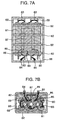
- Fig. 6 shows a cross-sectional view of a cylindrical type lithium secondary battery according to the present invention.
- the outside dimensions of the battery were 200 mm high and 60 mm in diameter.
- An electrode assembly was in a coiled structure comprising a positive electrode 61 comprising a positive electrode current collector 61a and a positive electrode mix 61b, a negative electrode 62 comprising a negative electrode current collector 62a and a negative electrode mix 62b, the positive electrode 61 and the negative electrode 62 being coiled through a separator 63 therebetween.
- Positive electrode leads 65 and negative electrode leads 67 welded to the top of the respective corresponding electrodes were provided at positions opposite to each other at a rate of 10 band-formed leads per electrode.
- the positive electrode leads 65 and the negative electrode leads 67 as a whole were welded to a positive electrode terminal 68 and a negative electrode terminal 69, respectively.
- the positive electrode terminal 68 and the negative electrode terminal 69 were fixed to a battery lid 71 in an insulated state by polypropylene packings. After laser welding of a tubular Al battery can 64 to the battery lid 71, the battery inside was evacuated in vacuum, while keeping a safety valve 80 having both functions of releasing the inside pressure and sealing the inlet for an electrolytic solution off the battery lid 71, and then the electrolytic solution was quickly introduced into the battery.
- the safety valve 80 was fixed to the battery lid 71 to tightly close the battery.
- the safety valve can release the gas when the inside pressure of the battery reaches 3 - 7 atmospheres.
- the cylindrical type battery had an average discharge voltage of 3.4 V and a rated capacity of 38 Ah with 130 Wh.
- Figs. 7A and 7B show the top view and the cross-sectional view of a battery assembly of the cylindrical type lithium secondary batteries.
- the battery assembly was in such a structure that total 8 cylindrical type batteries were arranged so that 4 thereof could take the upper position and the remaining 4 could take the lower position.
- Polytetrafluoroethylene fixing parts 82 were arranged as shown in Figs. 7a and 7b to fix 8 batteries 81.
- the positive electrode terminals 68 and the negative electrode terminals 69 of cylindrical type batteries 81 were connected by electric cables 83 so as to bring all the batteries into series connection with further connection to a positive electrode terminal 84 and a negative electrode terminal 85 of the battery assembly, respectively.
- the direction of the positive electrode terminals and the negative electrode terminals of the respective batteries 81 were alternated.
- the positive electrode terminals 68 and the negative electrode terminals 69 of the respective batteries 81 were connected to a control circuit substrate 87 through voltage input cables 86, respectively, to measure voltages of the respective batteries for charge/discharge control of the battery assembly.
- a thermocouple 89 was fixed to the inside surface of the battery arranged at the upper position to input its temperature signal to the control circuit substrate 87.
- the control circuit substrate 87 was provided with a microcomputer so as to have a function of stopping the charging/discharging of the battery assembly when the voltage of the batteries as a whole and the inside temperature of the battery assembly come off a given range.
- the battery assembly had an average discharge voltage of 27.2 V and a rated capacity of 38 Ah with 1,030 Wh.
- numeral 80 denotes a safty valve, 85 negative electrode terminal, 84 positive electrode terminal and 88 a container.
- Example 12 sets of battery assemblies having the same specification as in Example 6 were produced and arranged in series connection to provide a battery assembly module.
- the battery assembly module was mounted on an electric car.
- the battery assembly module was provided on the bottom of the electric car body.
- an output from the battery assembly module was adjusted to transmit power to a converter.
- the motor and wheels were driven to drive the electric car.
- the capacity reduction ratio of the battery assemblies was 2-5% after 100 runs of driving.
- Si particles having an average particle size of 10 ⁇ m and graphite particles having an average particle size of 20 ⁇ m were joined together in a ratio of 50:50 by weight and subjected to repetitions of mechanical pressure welding in a planetary ball mill for 24 hours, where the ball mill vessel and balls were made from stainless steel, and the powder preparation and the ball mill treatment were carried out in an Ar atmosphere.
- LiCoO 2 powder having an average particle size to 10 ⁇ m was used for a positive electrode-active material.
- the LiCoO 2 powder, graphite and PVDF were mixed together in a ratio of 90:6:4 by weight to form a slurry.
- PVDF was used in solution in N-methylpyrrolidone as in the case of the negative electrode.
- the slurry was thoroughly kneaded and applied to a 20 ⁇ m-thick Al foil, followed by drying at 120°C for one hour, press molding into an electrode piece by a roller press and ultimate blanking of the electrode piece into a positive electrode, 20 mm in diameter.
- a ratio of the positive electrode mix to the negative electrode mix was 15 owing to the larger negative electrode capacity.
- the negative electrode and the positive electrode so prepared were built into a coin type battery as shown in Fig. 1 to evaluate their characteristics.
- a positive electrode 21 comprising a positive electrode current collector 2a and a positive electrode mix 2b was mounted on a stainless steel positive electrode can 1 by spot welding
- a negative electrode 4 comprising a negative electrode current collector 4a and a negative electrode mix 4b was mounted on a stainless steel negative electrode can 3 by spot welding.
- Both the positive electrode and the negative electrode were impregnated with an electrolytic solution containing 1 mole/l of LiPF 6 in a 1:2 (by weight) solvent mixture of ethylene carbonate (EC) and dimethyl carbonate (DMC) and counterposed to each other through a polyethylene separator 5 therebetween.
- the positive electrode and the negative electrode can were pressure welded to each other through an insulating gasket 6.
- the resulting battery was subjected to a charging/discharging cycle test by charging with a charge current of 1 mA at a charge end voltage of 4.2 V and discharging with a discharge current of 1 mA at a discharge end voltage of 2.7 V.
- the initial discharge capacity of the battery was 12.5 mAh and the irreversible capacity ratio was 24%.
- a discharge capacity maintenance ratio of the 100th cycle to the 1st cycle was found to be 85%.
- Si particles having an average particle size of 1 ⁇ m and graphite particles having an average particle size of 20 ⁇ m were joined together in a ratio of 80:20 by weight and subjected to a ball mill treatment in a planetary ball mill for 48 hours, and then admixed with the same amount of the treated particles and further subjected to the ball mill treatment for 12 hours, where the ball mill vessel and balls were made from stainless steel and the powder preparation and the ball mill treatment were carried out in an Ar atmosphere.
- a battery using the Si-C composite powder as a negative electrode-active material was produced in the same manner as in Example 8, where LiCoO 2 having an average particle size of 10 ⁇ m was used for the negative electrode-active material, but a solution containing 1 mole/l of LiCPO 4 in a 1:2 (by weight) solvent mixture of EC and DMC was used as an electrolytic solution.
- the lithium secondary battery so produced was subjected to a charging/discharging cycle test by charging with a charge current of 1 mA at a charge end voltage of 4.2 V and discharging with a discharge current of 1 mA at a discharge end voltage of 2.7 V.
- the initial discharge capacity of the battery was found to be 11.0 mAh and the irreversible capacity ratio was found to be 20%.
- a discharge capacity maintenance ratio of the 100th cycle to the 1st cycle was found to be 88%.
- the Si-C composite powder prepared in Example 8, coal pitch and tetrahydrofuran were mixed together in a ratio of 100:30:300 by weight and stirred under reflux for one hour. Tetrahydrofuran was removed therefrom in a rotary evaporator, followed by vacuum drying at 150°C for 3 hours, thereby obtaining a Si-C composite powder/pitch composite material. Then, the composite material was disintegrated to 200-mesh and under in a cutter mill, heated up to 250°C in air at a rate of 3°C/min and maintained at that temperature for one hour. Then, the product was heated up to 1,000°C in a nitrogen gas stream at a rate of 20°C/h and maintained at that temperature, thereby carbonizing the pitch.
- the carbonized product was disintegrated to 200-mesh and under in a cutter mill, thereby obtaining a Si-C composite powder.
- Analysis of the resulting Si-C composite powder by X-ray diffraction revealed that peaks showing diffractions of C and Si were observed.
- the d (002) interplanar spacing of C was found to be 0.3359 nm and 0.3365 nm as two peaks. No silicon carbide diffraction peaks were observed.
- the R value was found to be 0.6 and the Si-C composite powder had a specific surface area of 35 m 2 /g.
- a battery using the Si-C composite powder as a negative electrode-active material was produced in the same manner as in Example 8, but LiNi 0.8 Co 0.2 O 2 having an average particle size of 10 ⁇ m was used as a positive electrode-active material, and a solution containing 1 mole/l of LiPF 6 in a 3:6:1 (by weight) solvent mixture of EC, DMC and DEC was used as an electrolytic solution.
- the battery so produced was subjected to a charging/discharging cycle test by charging with a charge current of 1 mA at a charge end voltage of 4.15 V and discharging with a discharge current of 1 mA at a discharge end voltage of 2.8 V.
- the initial discharge capacity of the battery was 10.2 mAh and the irreversible capacity ratio was 19%.
- a discharge capacity maintenance ratio of the 100th cycle to the 1st cycle was found to be 92%.
- the Si-C composite powder prepared in Example 10 graphite powder having an average particle size of 15 ⁇ m and PVDF were mixed together in a ratio of 30:70:10 by weight to prepare a slurry. After thorough kneading of the slurry, a negative electrode was prepared, using the slurry in the same manner as in Example 1, and a coin type battery was produced in the same manner as in Example 8, where LiMn 2 O 4 having an average particle size of 10 ⁇ m was used as a positive electrode-active material.
- the lithium secondary battery so produced was subjected to a charging/discharging test by charging with a charge current of 1 mA at a charge end voltage of 4.3 V and discharging with a discharge current of 1 mA at a discharge end voltage of 2.8 V.
- the initial discharge capacity of the battery was 34.8 mAh and the irreversible capacity ratio was 12%.
- a discharge capacity maintenance ratio of the 100th cycle to the first cycle was found to be 96%.
- Ge particles having an average particle size of 20 ⁇ m and graphite particles having an average particle size of 10 ⁇ m were joined together in a ratio of 70:30 by weight and subjected to a ball mill treatment for 6 hours, where the ball mill vessel and balls were made from stainless steel and the powder preparation and the ball mill treatment were carried out in an Ar atmosphere. Furthermore, the product was heated at 900°C in an Ar atmosphere for 5 hours. Analysis of the resulting Ge-C composite powder by wide angle X-ray diffraction revealed that peaks showing diffractions of C and Ge were observed. The d (002) interplanar spacing of C was found to be 0.3355 nm and Lc was found to be 55 nm. No germanium carbide diffraction peaks were observed.
- the R value was found to be 0.2.
- the Ge particles were embedded in the carbonaceous material and had an average particle size of 2.3 ⁇ m.
- the Ge-C composite powder had a specific surface area of 49 m 2 /g.
- a battery using the Ge-C composite powder as a negative electrode-active material was produced in the same manner as in Example 8, where LiNiO 2 having an average particle size of 15 ⁇ m was used as a positive electrode-active material and EPDM was used as a binder to prepare a slurry together with xylylene, followed by drying based on vacuum degassing at room temperature.
- a solution containing 1 mole/l of lithium borofluoride LiBF 4 dissolved in a 1:2 (by weight) solvent mixture of EC and EMC was used as an electrolytic solution.
- the lithium secondary battery so produced was subjected to a charging/discharging cycle test by charging with a charge current of 0.5mA at a charge end voltage of 4.2 V and discharging with a discharge current of 0.5 mA at a discharge end voltage of 2.7 V.
- the initial discharge capacity of the battery was 10.5 mAh and the irreversible capacity ratio was 22%.
- a discharge capacity maintenance ratio of the 100th cycle to the 1st cycle was found to be 86%.
- Ge particles having an average particle size of 10 ⁇ m and graphite particles having an average particle size of 10 ⁇ m were joined together in a ratio of 20:80 by weight and subjected to a ball mill treatment for 72 hours, where the ball mill vessel and balls were made from stainless steel, and the powder preparation and the ball mill treatment were carried out in an Ar atmosphere. Furthermore, the product was heated at 1,000°C in an Ar atmosphere for one hour. The resulting Ge-C composite powder, coal pitch and tetrahydrofuran were mixed together in a ratio of 100:50:500 by weight and stirred under reflux for one hour.
- Tetrahydrofuran was removed therefrom in a rotary evaporator, followed by vacuum drying at 150°C for 3 hours, thereby obtaining a Ge-C composite powder/pitch composite material.
- the composite material was disintegrated to 200-mesh and under in a cutter mill, heated up to 250°C in air at a rate of 3°C/min and maintained at that temperature for one hour. Then, the product was heated up to 1,200°C in a nitrogen gas stream at a rate of 20°C/h and maintained at that temperature, thereby carbonizing the coal pitch.
- the carbonized product was disintegrated to 200-mesh and under in a cutter mill, thereby obtaining a Ge-C composite powder.
- a battery using the Ge-C composite powder as a negative electrode-active material was produced in the same manner as in Example 1, where a solution containing 1.5 moles/l of LiPF 6 dissolved in a 2:3 (by weight) solvent mixture of PC and DMC was used as an electrolytic solution.
- the lithium secondary battery so produced was subjected to a charging/discharging cycle test by charging with a charge current of 2 mA at a charge end voltage of 4.2 V and discharging with a discharge current of 2mA at a discharge end voltage of 2.7 V.
- the initial charge capacity of the battery was 6.0 mAh and the irreversible capacity ratio was 15%.
- a discharge capacity maintenance ratio of the 100th cycle to the 1st cycle was found to be 93%.
- Si particles having an average particle size of 10 ⁇ m and graphite particles having an average particle size of 20 ⁇ m were joined together in a ratio of 20:80 by weight and subjected to a ball mill treatment for 48 hours, where the ball mill vessel and balls were made from stainless steel and the powder preparation and the ball mill treatment were carried out in an Ar atmosphere.
- the resulting Si-C composite powder, petroleum pitch and tetrahydrofuran were mixed together in a ratio of 100:70:700 by weight and stirred under reflux for one hour. Tetrahydrofuran was removed therefrom in a rotary evaporator, followed by vacuum drying at 150°C for 3 hours, thereby obtaining a Si-C composite powder/pitch composite material.
- the composite material was disintegrated to 200-mesh and under in a cutter mill, heated up to 350°C in air at a rate of 3°C/min and maintained at that temperature for one hour. Then, the product was heated up to 1,100°C in a nitrogen gas stream at a rate of 20°C/h and maintained at that temperature, thereby carbonizing the petroleum pitch. The carbonized product was disintegrated to 200-mesh and under in a cutter mill, thereby obtaining a Si-C composite powder. Analysis of the resulting Si-C composite powder by wide angle X-ray diffraction revealed that peaks showing diffractions of C, Si and silicon carbide were observed.
- the d (002) interplanar spacing of C was found to be 0.3361 nm and 0.3378 nm as two peaks, but the d (002) interplanar spacing determined from the peak showing a maximum intensity was found to be 0.3361 nm.
- a diffraction peak intensity ratio of silicon carbide at the position of 2 ⁇ about 35 deg to the background was found to be 0.1.
- the average particle size of Si particles determined by cross-sectional observation was found to be 2.2 ⁇ m and the R value was found to be 1.3.
- the Si-C composite powder had a specific surface area of 20 m 2 /g.
- a battery using the Si-C composite powder as a negative electrode-active material was produced in the same manner as in Example 1, where a solution containing 1.5 moles/l of LiPF 6 dissolved in a 1:2 (by weight) solvent mixture of EC and DMC was used as an electrolytic solution.
- the lithium secondary battery so produced was subjected to a charging/discharging cycle test by charging with a charge current of 2 mA at a charge end voltage of 4.2 V and discharging with a discharge current of 2 mA at a discharge end voltage of 2.7 V.
- a discharge capacity maintenance ratio of the 100th cycle to the 1st cycle was found to be 95%.
- Si particles having an average particle size of 1 ⁇ m, petroleum pitch and tetrahydrofuran were mixed together in a ratio of 100:70:700 by weight and stirred under reflux for one hour. Tetrahydrofuran was removed in rotary evaporator, followed by vacuum drying at 150°C to 3 hours, obtaining a Si/pitch composite material.
- the composite material was disintegrated to 200-mesh and under in a cutter mill, heated to 250°C in air at a rate of 3°C/min and maintained at that temperature for one hour. Then, the product was heated up to 1,100°C in a nitrogen gas stream at a rate of 20°C/h and maintained at that temperature, thereby carbonizing the pitch.
- the carbonized product was disintegrated to 200-mesh and under in a cutter mill, thereby obtaining a Si-C composite powder.
- Analysis of the resulting Si-C composite powder by wide angle X-ray diffraction revealed that peaks showing diffractions of C, Si and silicon carbide were observed, where the diffraction peak intensity of the silicon carbide was weak.
- the d (002) interplanar spacing of C was found to be 0.3369 nm and Lc was found to be 15 nm.
- the R value was found to be 1.4.
- the Si-C composite powder had a specific surface area of 7 m 2 /g.
- a battery using the Si-C composite powder as a negative electrode-active material was produced in the same manner as in Example 1, where a solution containing 1.0 mole/l of LiPF 6 dissolved in a 1:2 (by weight) solvent mixture of EC and DMC was used as an electrolytic solution.
- the lithium secondary battery so produced was subjected to a charging/discharging cycle test by charging with a charge current of 1 mA at a charge end voltage of 4.2 V and discharging with a discharge current of 1 mA at a discharge end voltage of 2.7 V.
- the initial discharge capacity of the battery was 15.3 mAh and the irreversible capacity ratio was 23%.
- a discharge capacity maintenance ratio of the 100th cycle to the 1st cycle was found to be 81%.
- Si particles having an average particle size of 3 ⁇ m and graphite particles having an average particle size of 20 ⁇ m were joined together in a ratio of 30:70 by weight and subjected to a ball mill treatment for 72 hours, where the ball mill vessel and balls were made from stainless steel, and the powder preparation and the ball mill treatment were carried out in an Ar atmosphere.
- the resulting Si-C composite powder, coal pitch and tetrahydrofuran were mixed together in a ratio of 100:50:500 by weight and stirred under reflux for one hour. Tetrahydrofuran was removed therefrom in a rotary evaporator, followed by vacuum drying at 150°C for 3 hours, thereby obtaining a Si-C composite powder/pitch composite material.
- the composite material was disintegrated to 200-mesh and under in a cutter mill, heated up to 250°C in air at a rate of 3°C/min and maintained at that temperature for one hour. Then, the product was heated up to 1,800°C in a nitrogen gas stream at a rate of 20°C/h and maintained at that temperature for one hour, thereby carbonizing the pitch. The carbonized product was disintegrated to 200-mesh and under in a cutter mill, thereby obtaining a Si-C composite powder. Analysis of the resulting Si-C composite powder by wide angle X-ray diffraction revealed that peaks showing diffractions of C, Si and silicon carbide were observed, where the diffraction peak intensity of silicon carbide was weak.
- the d (002) interplanar spacing of C was found to be 0.3359 nm.
- the R value was found to be 0.6.
- the Si-C composite powder had a specific surface area of 36 m 2 /g.
- a battery using the Si-C composite powder as a negative electrode-active material was produced in the same manner as in Example 8, where a solution containing 1.0 mole/l of LiPF 6 dissolved in a 1:2 (by weight) solvent mixture of EC and DMC was used as an electrolytic solution.
- the lithium secondary battery so produced was subjected to a charging/discharging cycle test by charging with a charge current of 1 mA at a charge end voltage of 4.2 V and discharging with a discharge current of 1 mA at a discharge end voltage of 2.7 V.
- the initial discharge capacity of the battery was 1.6 mAh and the irreversible capacity ratio was 3.8%.
- a discharge capacity maintenance ratio of the 100th cycle to the 1st cycle was found to be 98%.
- Si particles having an average particle size of 1 ⁇ m, petroleum pitch and tetrahydrofuran were mixed together in a ratio of 100:50:500 by weight and stirred under reflux for one hour. Tetrahydrofuran was removed therefrom in a rotary evaporator, followed by vacuum drying at 150°C for 3 hours, thereby obtaining a Si/pitch composite material.
- the composite material was disintegrated to 200-mesh and under in a cutter mill, heated up to 250°C in air at a rate of 3°C/min and maintained at that temperature for one hour. Then, the product was heated up to 700°C in a nitrogen gas stream at a rate of 20°C/h and maintained at that temperature for one hour, thereby carbonizing the pitch.
- the carbonized product was disintegrated to 200-mesh and under in a cutter mill, thereby obtaining a Si-C composite powder.
- Analysis of the resulting Si-C composite powder by wide angle X-ray diffraction revealed that peaks showing diffractions of C, Si and silicon carbide were observed, where the diffraction peak intensity of silicon carbide was weak.
- the d (002) interplanar spacing of C was found to be 0.359 nm.
- the R value was found to be 1.7.
- the Si-C composite powder had a specific surface area of 7 m 2 /g.
- a battery using the Si-C composite powder as a negative electrode-active material was produced in the same manner as in Example 8, where a solution containing 1.0 mole/l of LiPF 6 dissolved in a 1:2 (by weight) solvent mixture of EC and DMC was used as an electrolytic solution.
- the lithium secondary battery so produced was subjected to a charging/discharging cycle test by charging with a charge current of 1 mA at a charge end voltage of 4.2 V and discharging with a discharge current of 1 mA at a discharge end voltage of 2.7 V.
- the initial discharge capacity of the battery was 16.2 mAh and the irreversible capacity ratio was 25%.
- a discharge capacity maintenance ratio of the 100th cycle to the 1st cycle was found to be 2%.
- a lithium secondary battery having distinguished cycle characteristics as not obtainable from by a negative electrode-active material containing single particles comprising at least one of elements capable of forming a compound with Li and a high capacity as not obtainable from a carbonaceous material can be provided in the present invention by using a negative electrode-active material containing particles comprising a carbonaceous material and at least one of elements capable of forming a compound with Li, the carbonaceous material has a d (002) interplanar spacing by X-ray diffraction of 0.3350 nm - 0.3450 nm, the particles being embedded in a plurality of layers of the carbonaceous material.
Landscapes
- Chemical & Material Sciences (AREA)
- Chemical Kinetics & Catalysis (AREA)
- Electrochemistry (AREA)
- General Chemical & Material Sciences (AREA)
- Engineering & Computer Science (AREA)
- Composite Materials (AREA)
- Materials Engineering (AREA)
- Inorganic Chemistry (AREA)
- Manufacturing & Machinery (AREA)
- Secondary Cells (AREA)
- Battery Electrode And Active Subsutance (AREA)
Abstract
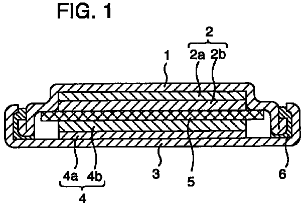
Description
Claims (12)
- A lithium secondary battery, which comprises a positive electrode (2, 13, 31, 61), a negative electrode (4, 16, 32, 62) containing a lithium ion-storable/dischargeable negative electrode-active material and lithium ion conductive, non-aqueous electrolytic solution or polymer electrolyte, the negative electrode-active material containing a carbonaceous material and particles comprising at least one of elements capable of forming a compound with lithium, the elements having a melting point of at least 900°C and a thermal expansion coefficient of not more than 9 ppm/K at room temperature, the particles being embedded in a plurality of layers of the carbonaceous materials, and the particles together with a carbonaceous material being subjected to a mechanical treatment to make size reduction of the initial particle sizes in advance.
- A lithium secondary battery according to Claim 1, wherein the elements capable of forming a compound with lithium are at least one element selected from silicon and germanium.
- A lithium secondary battery according to Claim 1, wherein the carbonaceous material for a plurality of layers comprises a carbonaceous material (A) and a carbonaceous material (B), the carbonaceous material (A) being enclosed by the carbonaceous material (B).
- A lithium secondary battery according to Claim 3, wherein the carbonaceous material (A) is composed of crystalline carbon and the carbonaceous material (B) is composed of amorphous carbon.
- A lithium secondary battery according to Claim 3, wherein the carbonaceous material (B) is harder than the carbonaceous material (A).
- A lithium secondary battery according to Claim 1, wherein at least one of the elements capable of forming a compound with lithium is contained in an amount of less than 30% by weight on the basis of sum total of the negative electrode-active material.
- A method for using a lithium secondary battery according to Claim 1 in an electric car as a battery assembly.
- A process for producing a lithium secondary battery, which comprises:(a) a step of mechanically treating a carbonaceous material (A) and at least one of elements capable of forming a compound with lithium and having a melting point of at least 900°C and a thermal expansion coefficient of not more than 9 ppm/K at room temperature,(b) a step of mixing the particles resulting from the step (a) and a precursor of a carbonaceous material (B),(c) a step of carbonizing the particles resulting from the step (b), thereby forming a negative electrode-active material, and(d) a step of arranging a positive electrode (2, 13, 31, 61), a negative electrode (4, 16, 32, 62) containing said negative electrode-active material and a lithium ion conductive, non-aqueous electrolytic solution or polymer electrolyte into a container.
- A process according to Claim 8, wherein at least one of the elements capable of forming a compound with lithium is at least one element selected from silicon and germanium.
- A process according to Claim 8, wherein heat treatment is carried out after the step (a).
- A process according to Claim 8, wherein the step (a) comprise pulverization with a ball mill.
- A process according to Claim 8, wherein the step (a) comprises mechanical pressure welding.
Applications Claiming Priority (2)
| Application Number | Priority Date | Filing Date | Title |
|---|---|---|---|
| JP738099 | 1999-01-14 | ||
| JP738099 | 1999-01-14 |
Publications (3)
| Publication Number | Publication Date |
|---|---|
| EP1020944A2 true EP1020944A2 (en) | 2000-07-19 |
| EP1020944A3 EP1020944A3 (en) | 2003-12-17 |
| EP1020944B1 EP1020944B1 (en) | 2011-12-07 |
Family
ID=11664345
Family Applications (1)
| Application Number | Title | Priority Date | Filing Date |
|---|---|---|---|
| EP00100127A Expired - Lifetime EP1020944B1 (en) | 1999-01-14 | 2000-01-07 | Lithium secondary battery, and process for producing the same |
Country Status (3)
| Country | Link |
|---|---|
| US (2) | US6524749B1 (en) |
| EP (1) | EP1020944B1 (en) |
| KR (1) | KR100683549B1 (en) |
Cited By (7)
| Publication number | Priority date | Publication date | Assignee | Title |
|---|---|---|---|---|
| EP1225647A3 (en) * | 2001-01-17 | 2005-05-11 | Nisshinbo Industries, Inc. | Active electrode compositions for secondary lithium batteries and carbonaceous material powder mixture for electrical double-layer capacitors |
| EP1205989A3 (en) * | 2000-11-14 | 2005-11-09 | Mitsui Mining Co., Ltd. | Composite material for anode of lithium secondary battery, and lithium secondary battery |
| KR100908573B1 (en) * | 2009-02-03 | 2009-07-22 | 안혁 | Pole plate processing unit of lithium ion polymer battery for hybrid vehicle |
| EP1702375A4 (en) * | 2003-12-19 | 2009-11-04 | Conocophillips Co | CARBON COATED SILICON PARTICULATE POWDER AS ANODE FOR LITHIUM ION BATTERIES AND PROCESS FOR PRODUCING THE SAME |
| US7785661B2 (en) | 2003-12-19 | 2010-08-31 | Conocophillips Company | Methods of preparing composite carbon-graphite-silicon particles and using same |
| US9444094B2 (en) | 2013-04-25 | 2016-09-13 | Toyota Motor Engineering & Manufacturing North America, Inc. | Preparation of high energy-density electrode materials for rechargeable magnesium batteries |
| CN104662703B (en) * | 2012-09-26 | 2018-03-30 | 三洋电机株式会社 | Sealed batteries and electric vehicles |
Families Citing this family (42)
| Publication number | Priority date | Publication date | Assignee | Title |
|---|---|---|---|---|
| WO2002065561A1 (en) * | 2001-02-14 | 2002-08-22 | Sony Corporation | Non-aqueous electrolytic battery |
| JP2003017038A (en) * | 2001-06-28 | 2003-01-17 | Sanyo Electric Co Ltd | Anode for lithium battery and lithium battery |
| US7393476B2 (en) * | 2001-11-22 | 2008-07-01 | Gs Yuasa Corporation | Positive electrode active material for lithium secondary cell and lithium secondary cell |
| CN100414743C (en) | 2002-05-08 | 2008-08-27 | 株式会社杰士汤浅 | A non-aqueous electrolyte secondary battery |
| US20040137327A1 (en) * | 2003-01-13 | 2004-07-15 | Gross Karl J. | Synthesis of carbon/silicon composites |
| KR100570637B1 (en) * | 2003-05-21 | 2006-04-12 | 삼성에스디아이 주식회사 | Anode Active Material for Lithium Secondary Battery and Manufacturing Method Thereof |
| JP2005108515A (en) * | 2003-09-29 | 2005-04-21 | Sanyo Electric Co Ltd | Nonaqueous electrolyte battery |
| KR100601562B1 (en) * | 2004-07-29 | 2006-07-19 | 삼성에스디아이 주식회사 | Electrode Assembly and Lithium Secondary Battery Using the Same |
| JP4550519B2 (en) * | 2004-08-10 | 2010-09-22 | セイコーインスツル株式会社 | Electrochemical cell and method for producing the same |
| JP4213687B2 (en) * | 2005-07-07 | 2009-01-21 | 株式会社東芝 | Nonaqueous electrolyte battery and battery pack |
| ATE556461T1 (en) * | 2006-02-17 | 2012-05-15 | Emw Energy Co Ltd | CYLINDRICAL ZINC-AIR CELL AND PRODUCTION METHOD THEREOF |
| JP5147206B2 (en) * | 2006-08-11 | 2013-02-20 | 三洋電機株式会社 | Nonaqueous electrolyte secondary battery |
| KR100938059B1 (en) * | 2007-10-23 | 2010-01-21 | 삼성에스디아이 주식회사 | Anode for lithium secondary battery and lithium secondary battery using same |
| JP5111421B2 (en) * | 2009-03-27 | 2013-01-09 | 株式会社日立製作所 | Positive electrode material for lithium secondary battery, lithium secondary battery, and secondary battery module using the same |
| US8268467B2 (en) * | 2009-03-30 | 2012-09-18 | Lenovo (Singapore) Pte. Ltd. | Battery safety features |
| KR101155909B1 (en) * | 2010-01-07 | 2012-06-20 | 삼성에스디아이 주식회사 | Negative active material for rechargeable lithium battery, method of preparing same, and rechargeable lithium battery including same |
| US20110183185A1 (en) * | 2010-01-22 | 2011-07-28 | Lanyang Energy Technology Co., Ltd. | High power lithium-ion battery |
| US9786947B2 (en) | 2011-02-07 | 2017-10-10 | Sila Nanotechnologies Inc. | Stabilization of Li-ion battery anodes |
| CN103515657B (en) * | 2012-06-25 | 2017-06-27 | 苏州宝时得电动工具有限公司 | Battery |
| US20150072261A1 (en) * | 2013-09-06 | 2015-03-12 | Matthew Mench | High power high efficiency flow type battery |
| WO2016187143A1 (en) | 2015-05-15 | 2016-11-24 | Composite Materials Technology, Inc. | Improved high capacity rechargeable batteries |
| CN108475761B (en) * | 2015-12-28 | 2023-10-27 | 庄信万丰股份有限公司 | Silicon-based materials and methods of making and using the same |
| CN107528090A (en) * | 2016-06-20 | 2017-12-29 | 兴能高科技股份有限公司 | Secondary lithium battery structure |
| US10797314B2 (en) | 2016-07-29 | 2020-10-06 | Blue Current, Inc. | Compliant solid-state ionically conductive composite materials and method for making same |
| KR20190077321A (en) | 2016-09-01 | 2019-07-03 | 컴포짓 매터리얼스 테크놀로지, 아이엔씨. | Nano-scale / nano-structured Si coating on valve metal substrate for LIB anode |
| CN110300950B (en) | 2017-02-06 | 2023-06-16 | 平蛙实验室股份公司 | Optical Coupling in Touch Sensing Systems |
| US20180254518A1 (en) | 2017-03-03 | 2018-09-06 | Blue Current, Inc. | Polymerized in-situ hybrid solid ion-conductive compositions |
| US10457781B2 (en) | 2017-03-03 | 2019-10-29 | Blue Current, Inc. | Polymerized in-situ hybrid solid ion-conductive compositions |
| CN111052058B (en) | 2017-09-01 | 2023-10-20 | 平蛙实验室股份公司 | Improved optics |
| US11567610B2 (en) | 2018-03-05 | 2023-01-31 | Flatfrog Laboratories Ab | Detection line broadening |
| CN111344884B (en) | 2018-03-30 | 2023-09-29 | 松下控股株式会社 | Negative electrode for non-aqueous electrolyte secondary battery and non-aqueous electrolyte secondary battery |
| CN112889016A (en) | 2018-10-20 | 2021-06-01 | 平蛙实验室股份公司 | Frame for touch sensitive device and tool therefor |
| US11581570B2 (en) | 2019-01-07 | 2023-02-14 | Blue Current, Inc. | Polyurethane hybrid solid ion-conductive compositions |
| EP4066089B1 (en) | 2019-11-25 | 2024-09-25 | FlatFrog Laboratories AB | A touch-sensing apparatus |
| EP4078698A4 (en) | 2019-12-20 | 2024-08-14 | Blue Current, Inc. | COMPOSITE ELECTROLYTES WITH BINDERS |
| US11394054B2 (en) | 2019-12-20 | 2022-07-19 | Blue Current, Inc. | Polymer microspheres as binders for composite electrolytes |
| US12166239B2 (en) | 2019-12-20 | 2024-12-10 | Blue Current, Inc. | Polymer microspheres as binders for composite electrolytes |
| WO2021158164A1 (en) | 2020-02-08 | 2021-08-12 | Flatfrog Laboratories Ab | Touch apparatus with low latency interactions |
| CN111430832B (en) * | 2020-03-11 | 2021-06-29 | 中南大学 | A full resource recovery method for waste ternary lithium-ion batteries without discharge pretreatment |
| WO2021189241A1 (en) * | 2020-03-24 | 2021-09-30 | 东莞新能安科技有限公司 | Method for charging electrochemical device, electronic device, and readable storage medium |
| CN112133952B (en) * | 2020-09-30 | 2025-08-12 | 武汉逸飞激光股份有限公司 | Automatic mechanical kneading flat head of gathering dust and electric core kneading flat device thereof |
| US12587012B2 (en) * | 2022-06-06 | 2026-03-24 | Rv Mobile Power, Llc | Compact energy system for managing mobile power |
Family Cites Families (13)
| Publication number | Priority date | Publication date | Assignee | Title |
|---|---|---|---|---|
| JP3369589B2 (en) | 1992-04-07 | 2003-01-20 | 三菱化学株式会社 | Electrode material |
| JP3410757B2 (en) | 1993-03-23 | 2003-05-26 | 三菱化学株式会社 | Electrode material |
| US5434022A (en) * | 1993-10-08 | 1995-07-18 | Hughes Aircraft Company | Electrodes and electrochemical storage cells utilizing tin-modified active materials |
| CA2122770C (en) * | 1994-05-03 | 2000-10-03 | Moli Energy (1990) Limited | Carbonaceous host compounds and use as anodes in rechargeable batteries |
| US5753387A (en) * | 1995-11-24 | 1998-05-19 | Kabushiki Kaisha Toshiba | Lithium secondary battery |
| JPH09249407A (en) * | 1996-03-14 | 1997-09-22 | Toyota Central Res & Dev Lab Inc | Graphite composite and method for producing the same |
| JPH09320599A (en) * | 1996-05-30 | 1997-12-12 | Ricoh Co Ltd | Nonaqueous electrolyte secondary battery |
| JPH103920A (en) | 1996-06-17 | 1998-01-06 | Toshiba Corp | Lithium secondary battery and method of manufacturing the same |
| WO1998053511A1 (en) * | 1997-05-19 | 1998-11-26 | Toyo Tanso Co., Ltd. | Carbonaceous material for the anode of lithium ion secondary cell and lithium ion secondary cell made by using the carbonaceous material |
| JPH1140158A (en) * | 1997-05-19 | 1999-02-12 | Toyo Tanso Kk | Carbon material for negative electrode of lithium ion secondary battery, and lithium ion secondary battery using the carbon material for negative electrode |
| EP0883199B1 (en) * | 1997-06-03 | 2003-05-07 | Matsushita Electric Industrial Co., Ltd. | Negative electrode materials for non-aqueous electrolyte secondary batteries and said batteries employing the same materials |
| JPH11339778A (en) * | 1998-05-25 | 1999-12-10 | Kao Corp | Method for producing negative electrode for secondary battery |
| JP2948206B1 (en) * | 1998-05-25 | 1999-09-13 | 花王株式会社 | Anode materials for non-aqueous secondary batteries |
-
2000
- 2000-01-07 EP EP00100127A patent/EP1020944B1/en not_active Expired - Lifetime
- 2000-01-13 US US09/482,644 patent/US6524749B1/en not_active Expired - Lifetime
- 2000-01-14 KR KR1020000001634A patent/KR100683549B1/en not_active Expired - Lifetime
-
2002
- 2002-12-31 US US10/331,648 patent/US7416814B2/en not_active Expired - Fee Related
Cited By (7)
| Publication number | Priority date | Publication date | Assignee | Title |
|---|---|---|---|---|
| EP1205989A3 (en) * | 2000-11-14 | 2005-11-09 | Mitsui Mining Co., Ltd. | Composite material for anode of lithium secondary battery, and lithium secondary battery |
| EP1225647A3 (en) * | 2001-01-17 | 2005-05-11 | Nisshinbo Industries, Inc. | Active electrode compositions for secondary lithium batteries and carbonaceous material powder mixture for electrical double-layer capacitors |
| EP1702375A4 (en) * | 2003-12-19 | 2009-11-04 | Conocophillips Co | CARBON COATED SILICON PARTICULATE POWDER AS ANODE FOR LITHIUM ION BATTERIES AND PROCESS FOR PRODUCING THE SAME |
| US7785661B2 (en) | 2003-12-19 | 2010-08-31 | Conocophillips Company | Methods of preparing composite carbon-graphite-silicon particles and using same |
| KR100908573B1 (en) * | 2009-02-03 | 2009-07-22 | 안혁 | Pole plate processing unit of lithium ion polymer battery for hybrid vehicle |
| CN104662703B (en) * | 2012-09-26 | 2018-03-30 | 三洋电机株式会社 | Sealed batteries and electric vehicles |
| US9444094B2 (en) | 2013-04-25 | 2016-09-13 | Toyota Motor Engineering & Manufacturing North America, Inc. | Preparation of high energy-density electrode materials for rechargeable magnesium batteries |
Also Published As
| Publication number | Publication date |
|---|---|
| US20030091901A1 (en) | 2003-05-15 |
| US7416814B2 (en) | 2008-08-26 |
| EP1020944A3 (en) | 2003-12-17 |
| EP1020944B1 (en) | 2011-12-07 |
| KR100683549B1 (en) | 2007-02-15 |
| US6524749B1 (en) | 2003-02-25 |
| KR20000053488A (en) | 2000-08-25 |
Similar Documents
| Publication | Publication Date | Title |
|---|---|---|
| EP1020944B1 (en) | Lithium secondary battery, and process for producing the same | |
| US6638662B2 (en) | Lithium secondary battery having oxide particles embedded in particles of carbonaceous material as a negative electrode-active material | |
| US8039151B2 (en) | Negative electrode active material, nonaqueous electrolyte battery, battery pack and vehicle | |
| US7820327B2 (en) | Lithium titanate and lithium cells and batteries including the same | |
| JP3866740B2 (en) | Non-aqueous electrolyte secondary battery, assembled battery and battery pack | |
| EP2784855B1 (en) | Positive electrode active material, nonaqueous electrolyte battery, and battery pack | |
| JP4103285B2 (en) | Lithium battery and manufacturing method thereof | |
| US11784314B2 (en) | Negative electrode for lithium secondary battery and lithium secondary battery including the same | |
| EP2851979A1 (en) | Electrode material for nonaqueous electrolyte secondary battery, electrode for nonaqueous electrolyte secondary, battery, nonaqueous electrolyte secondary battery, and battery pack | |
| JP7443579B2 (en) | Nonaqueous electrolyte batteries and battery packs | |
| CN112335076A (en) | Electrodes, cells and battery packs | |
| EP1959513A1 (en) | Composite anode active material,method of preparing the same,and anode and lithium battery containing the material | |
| US20230361269A1 (en) | Electrode, battery, and battery pack | |
| US10693128B2 (en) | Electrode for nonaqueous electrolyte battery, nonaqueous electrolyte battery including the same, and battery pack | |
| US10381649B2 (en) | Electrode material for nonaqueous electrolyte battery, electrode for nonaqueous electrolyte battery, nonaqueous electrolyte battery including the same, and battery pack | |
| JP2000268879A (en) | Lithium secondary battery | |
| JP7106749B2 (en) | Electrodes, batteries and battery packs | |
| JP7600254B2 (en) | Electrodes, batteries and battery packs | |
| US20210013497A1 (en) | Electrode, nonaqueous electrolyte battery, and battery pack | |
| KR102954868B1 (en) | Method for preparing cathode active material, cathode active material prepared using the same and lithium secondary battery comprising the same | |
| KR102947473B1 (en) | Cathode active material for lithium secondary battery and lithium secondary battery comprising the same | |
| KR102954869B1 (en) | Method for preparing cathode active material, cathode active material prepared using the same and lithium secondary battery comprising the same | |
| KR102940279B1 (en) | Cathode active material for lithium secondary battery and lithium secondary battery comprising the same | |
| WO2026062905A1 (en) | Electrode, secondary battery, and battery pack | |
| WO2023233520A1 (en) | Battery and battery pack |
Legal Events
| Date | Code | Title | Description |
|---|---|---|---|
| PUAI | Public reference made under article 153(3) epc to a published international application that has entered the european phase |
Free format text: ORIGINAL CODE: 0009012 |
|
| AK | Designated contracting states |
Kind code of ref document: A2 Designated state(s): AT BE CH CY DE DK ES FI FR GB GR IE IT LI LU MC NL PT SE |
|
| AX | Request for extension of the european patent |
Free format text: AL;LT;LV;MK;RO;SI |
|
| PUAL | Search report despatched |
Free format text: ORIGINAL CODE: 0009013 |
|
| AK | Designated contracting states |
Kind code of ref document: A3 Designated state(s): AT BE CH CY DE DK ES FI FR GB GR IE IT LI LU MC NL PT SE |
|
| AX | Request for extension of the european patent |
Extension state: AL LT LV MK RO SI |
|
| 17P | Request for examination filed |
Effective date: 20040416 |
|
| AKX | Designation fees paid |
Designated state(s): DE FR GB |
|
| 17Q | First examination report despatched |
Effective date: 20080222 |
|
| RAP1 | Party data changed (applicant data changed or rights of an application transferred) |
Owner name: HITACHI CHEMICAL COMPANY, LTD. |
|
| REG | Reference to a national code |
Ref country code: DE Ref legal event code: R079 Ref document number: 60046722 Country of ref document: DE Free format text: PREVIOUS MAIN CLASS: H01M0010400000 Ipc: H01M0004587000 |
|
| GRAP | Despatch of communication of intention to grant a patent |
Free format text: ORIGINAL CODE: EPIDOSNIGR1 |
|
| RIC1 | Information provided on ipc code assigned before grant |
Ipc: H01M 10/052 20100101ALI20110607BHEP Ipc: H01M 4/587 20100101AFI20110607BHEP Ipc: H01M 4/13 20100101ALI20110607BHEP Ipc: H01M 4/38 20060101ALI20110607BHEP |
|
| RIN1 | Information on inventor provided before grant (corrected) |
Inventor name: KANEDA, JUNYAC/O HITACHI, LTD., INTELLECTUAL PROPE Inventor name: MURANAKA, YASUSHIC/O HITACHI, LTD., INTELLECTUAL P Inventor name: AONO, YASUHISAC/O HITACHI, LTD., INTELLECTUAL PROP Inventor name: TAKEI, KOUICHI Inventor name: TAKEUCHI, SEIJIC/O HITACHI, LTD., INTELLECTUAL PRO Inventor name: WATANABE, NORIYUKIC/O HITACHI, LTD., INTELLECTUAL |
|
| GRAS | Grant fee paid |
Free format text: ORIGINAL CODE: EPIDOSNIGR3 |
|
| GRAA | (expected) grant |
Free format text: ORIGINAL CODE: 0009210 |
|
| RIN1 | Information on inventor provided before grant (corrected) |
Inventor name: TAKEUCHI, SEIJIC/O HITACHI, LTD., INTELLECTUAL PRO Inventor name: WATANABE, NORIYUKIC/O HITACHI, LTD., INTELLECTUAL Inventor name: KANEDA, JUNYAC/O HITACHI, LTD., INTELLECTUAL PROPE Inventor name: AONO, YASUHISAC/O HITACHI, LTD., INTELLECTUAL PROP Inventor name: TAKEI, KOUICHI Inventor name: MURANAKA, YASUSHIC/O HITACHI, LTD., INTELLECTUAL P |
|
| AK | Designated contracting states |
Kind code of ref document: B1 Designated state(s): DE FR GB |
|
| REG | Reference to a national code |
Ref country code: GB Ref legal event code: FG4D |
|
| REG | Reference to a national code |
Ref country code: DE Ref legal event code: R096 Ref document number: 60046722 Country of ref document: DE Effective date: 20120223 |
|
| PLBE | No opposition filed within time limit |
Free format text: ORIGINAL CODE: 0009261 |
|
| STAA | Information on the status of an ep patent application or granted ep patent |
Free format text: STATUS: NO OPPOSITION FILED WITHIN TIME LIMIT |
|
| 26N | No opposition filed |
Effective date: 20120910 |
|
| REG | Reference to a national code |
Ref country code: DE Ref legal event code: R097 Ref document number: 60046722 Country of ref document: DE Effective date: 20120910 |
|
| REG | Reference to a national code |
Ref country code: FR Ref legal event code: PLFP Year of fee payment: 17 |
|
| REG | Reference to a national code |
Ref country code: FR Ref legal event code: PLFP Year of fee payment: 18 |
|
| PGFP | Annual fee paid to national office [announced via postgrant information from national office to epo] |
Ref country code: DE Payment date: 20170120 Year of fee payment: 18 Ref country code: FR Payment date: 20170120 Year of fee payment: 18 |
|
| PGFP | Annual fee paid to national office [announced via postgrant information from national office to epo] |
Ref country code: GB Payment date: 20170119 Year of fee payment: 18 |
|
| REG | Reference to a national code |
Ref country code: DE Ref legal event code: R119 Ref document number: 60046722 Country of ref document: DE |
|
| GBPC | Gb: european patent ceased through non-payment of renewal fee |
Effective date: 20180107 |
|
| PG25 | Lapsed in a contracting state [announced via postgrant information from national office to epo] |
Ref country code: FR Free format text: LAPSE BECAUSE OF NON-PAYMENT OF DUE FEES Effective date: 20180131 Ref country code: DE Free format text: LAPSE BECAUSE OF NON-PAYMENT OF DUE FEES Effective date: 20180801 |
|
| REG | Reference to a national code |
Ref country code: FR Ref legal event code: ST Effective date: 20180928 |
|
| PG25 | Lapsed in a contracting state [announced via postgrant information from national office to epo] |
Ref country code: GB Free format text: LAPSE BECAUSE OF NON-PAYMENT OF DUE FEES Effective date: 20180107 |