EP1020885A2 - Electric field controller - Google Patents
Electric field controller Download PDFInfo
- Publication number
- EP1020885A2 EP1020885A2 EP00660005A EP00660005A EP1020885A2 EP 1020885 A2 EP1020885 A2 EP 1020885A2 EP 00660005 A EP00660005 A EP 00660005A EP 00660005 A EP00660005 A EP 00660005A EP 1020885 A2 EP1020885 A2 EP 1020885A2
- Authority
- EP
- European Patent Office
- Prior art keywords
- electric field
- field controller
- controller
- connection
- conductive
- Prior art date
- Legal status (The legal status is an assumption and is not a legal conclusion. Google has not performed a legal analysis and makes no representation as to the accuracy of the status listed.)
- Granted
Links
- 230000005684 electric field Effects 0.000 title claims abstract description 154
- 239000013013 elastic material Substances 0.000 claims abstract description 15
- 230000005611 electricity Effects 0.000 claims abstract description 6
- 239000000463 material Substances 0.000 claims description 28
- 230000005540 biological transmission Effects 0.000 claims description 2
- 230000009466 transformation Effects 0.000 description 7
- 238000009434 installation Methods 0.000 description 5
- 229910052751 metal Inorganic materials 0.000 description 5
- 239000002184 metal Substances 0.000 description 5
- 239000011347 resin Substances 0.000 description 5
- 229920005989 resin Polymers 0.000 description 5
- 239000004020 conductor Substances 0.000 description 4
- 239000011810 insulating material Substances 0.000 description 3
- OKTJSMMVPCPJKN-UHFFFAOYSA-N Carbon Chemical compound [C] OKTJSMMVPCPJKN-UHFFFAOYSA-N 0.000 description 2
- 229920002943 EPDM rubber Polymers 0.000 description 2
- 229910052799 carbon Inorganic materials 0.000 description 2
- 238000007688 edging Methods 0.000 description 2
- 230000000694 effects Effects 0.000 description 2
- 229920001971 elastomer Polymers 0.000 description 2
- 230000004907 flux Effects 0.000 description 2
- 230000001131 transforming effect Effects 0.000 description 2
- 239000004411 aluminium Substances 0.000 description 1
- 229910052782 aluminium Inorganic materials 0.000 description 1
- XAGFODPZIPBFFR-UHFFFAOYSA-N aluminium Chemical compound [Al] XAGFODPZIPBFFR-UHFFFAOYSA-N 0.000 description 1
- 230000001419 dependent effect Effects 0.000 description 1
- 230000009467 reduction Effects 0.000 description 1
- 238000007493 shaping process Methods 0.000 description 1
- 238000000844 transformation Methods 0.000 description 1
Images

Classifications
-
- H—ELECTRICITY
- H01—ELECTRIC ELEMENTS
- H01H—ELECTRIC SWITCHES; RELAYS; SELECTORS; EMERGENCY PROTECTIVE DEVICES
- H01H33/00—High-tension or heavy-current switches with arc-extinguishing or arc-preventing means
- H01H33/02—Details
- H01H33/24—Means for preventing discharge to non-current-carrying parts, e.g. using corona ring
-
- H—ELECTRICITY
- H02—GENERATION; CONVERSION OR DISTRIBUTION OF ELECTRIC POWER
- H02B—BOARDS, SUBSTATIONS OR SWITCHING ARRANGEMENTS FOR THE SUPPLY OR DISTRIBUTION OF ELECTRIC POWER
- H02B11/00—Switchgear having carriage withdrawable for isolation
- H02B11/02—Details
- H02B11/04—Isolating-contacts, e.g. mountings or shieldings
Definitions
- the invention relates to an electric field controller to be used with connections of energized parts in high and/or mid voltage apparatuses for controlling an electric field formed around the connections, the electric field controller comprising a curved body conducting electricity and being fixedly connected with the energized parts of the apparatuses.
- Electric field controllers are used in high and mid voltage apparatuses at extension and connection points in high and mid voltage busbar systems and cables therein or in other devices in the apparatuses.
- Owing to the design of the components to be connected such as busbars, cables, fuses or the like and the connection components to be used such as connectors, connection screws or the like sharp edges are formed therewith at the extension and connection points.
- the external dimensions thereof are reduced, which results in a reduction of the insulating airspace between energized parts and earthed body pads.
- the problem described above can be solved by employing at the extension and connection points an electric field controller, which is curved and forms a domed-shaped or spherical cover around the connection point and the components thereof in order to protect them.
- the electric field controller forms around the connection point an equipotential surface having the same voltage as the energized parts of the connection.
- the equipotential surface has no sharp edges, where the electric flux density would increase and which would operate as starting points for the impulse voltage discharges.
- the electric field controller thus enables to control the electric field generated between the energized parts and the earthed parts of the apparatuses in a controlled way and prevents flashovers to the earthed body parts of the apparatuses, thus improving the impulse voltage endurance of the apparatus.
- the use of the electric field controller also allows to shape the connection components within the cover more freely.
- a metallic electric field controller is difficult to form so as not to include sharp edges which are inconvenient for the control of an electric field.
- the metal or cast resin surface is liable to dents hampering the operation of the electric field controller and to other transformations occurring in connection with installation, as even minor sharp edges substantially impair the operation of an electric field controller.
- the structure of the electric field controller made of metal or cast resin is stiff, and sets requirements on the time for mounting the electric field controller in position when assembling the apparatus. An electric field controller having a stiff structure also impedes the assembly by reducing the assembling space within.
- the invention is based on the idea that by producing an electric field controller of elastic material, the electrical conductivity of which preferably being conductive or semi-conductive, an electric field controller is achieved that in relation to field control is made into a preferable shape, is durable, light and flexible regarding installation and easy to mount and to bend.
- An elastic electric field controller can be mounted in position at the connection as the last item after the other components have been mounted. Mounting is simply carried out by stretching or pulling the electric field controller around the connection. If the elastic electric field controller cannot be mounted in position before the other components have been mounted, the elastic material allows the electric field controller to be stretched or compressed in order to reveal the connection during installation, in which case the installation space to be used is increased. An elastic material endures dents better than a stiff material without substantially damaging the properties of the electric field controller associated with the control of the electric field. The chance for an elastic material to be damaged during installation is also inferior to that of a stiff material.
- An electric field controller made of elastic material remains in position owing to the tensile force and friction resulting from the elasticity of the material, wherefore no screws or other separate parts are needed for fastening the electric field controller into position. Since no through holes required by screws or other separate parts are needed in the structure, the electric field controller can in relation to the electric field control be shaped into a more preferable form.
- the use of an elastic material allows the electric field controller to be shaped more preferably at the connections of various energized components. Therefore, no particular attention has to be paid on shaping the connector components to be used on the connections to be as curved as possible.
- the same connector components can be used at connections of various requirement levels, since with a more demanding connection the electric field controller controls the electric field generated around the connector.
- the elastic material is formed more closely and more preferably at the connection point and forms, if the connection type allows it, a closed dome-shaped structure around the connection. It is easier to shape an elastic material than a stiff material into a preferable form in relation to the electric field control, thus referring to equally curved surfaces at all edges of the electric field controller.
- an elastic electric field controller are more advantageous than those an electric field controller made of metal or cast resin. This is economically significant, since the structure and form of the electric field controller varies according to the place of use and the type of connector, and consequently a plurality of electric field controllers shaped in various ways may be needed.
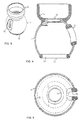
- FIGS 1 and 2 show a preferred embodiment of an electric field controller of the invention, a semi-spherical electric field controller.
- the electric field controller according to this embodiment is used with an ending voltage busbar connection.
- the electric field controller comprises a dome-shaped body 1, in which all surface parts are curved.
- the body is hollow and made of elastic material and the electrical conductivity thereof is essentially semi-conductive or conductive.
- Through holes 2 are formed into the side and skirt of the electric field controller body 1 for placing the electric field controller at the voltage busbar connection.
- the through holes at the side 2 and the skirt 3 of the electric field controller body 1 are formed so as to place the electric field controller on the connection firmly providing a fixed contact with the energized parts surrounding it and forming an equipotential surface having the same voltage as said parts.
- the electric field controller body 1 forms a dome-shaped cover controlling the electric field around the connector components, whereby the connector components surrounding the controller can be formed preferably in relation to the making of the connection without having to take into account the effect the form of the connector components causes to the impulse voltage endurance.
- the body 1 is made of an elastic and flexible material that reverts to its original form after a transformation caused.
- the electric field controller is mounted in position by causing a required transformation to the controller by pulling or stretching the electric field controller around the connection. Owing to the elasticity the skirt 3 of the electric field controller closes towards the connection and the electric field controller is then placed firmly around the connection and stays in position on account of the tensile force generated by friction and the elasticity of the material.
- the skirt 3 of the electric field controller also operates as a fastening means that fastens the electric field controller to the connection and no through holes or recesses required by separate fastening means, such as screws, have to be formed in the electric field controller body 1.
- the elastic material that reverts to its original form after transformation is not liable to be damaged either.
- the electric field controller body 1 is produced of a material, whose electrical conductivity is essentially semi-conductive or conductive.
- the material is, for example, an EPDM rubber which is tempered to be semi-conductive with carbon, the conductivity of the rubber is, for example, ⁇ ⁇ 0,052 ⁇ m. Since the electrical conductivity of the material is conductive or semi-conductive the electric field controller is at the same potential level with the connection components of the busbar when mounted in position.
- the structure of the electric field controller body 1 resembles a cover and the inner part thereof is preferably hollow.
- the electric field controller having a curved surface and the same voltage as the energized parts of the apparatus provides the required control properties of the electric field.
- the hollow structure of the electric field controller body 1 improves the manageability of the electric field controller when mounting is carried out. In addition the hollow structure reduces the consumption of production material and makes the electric field controller light in weight.
- the structure of the electric field controller body 1 may comprise one or more layers, the electrical conductivity of which varies or which are made of various materials. Then a layer composed of an insulating material or of an electrically conductive material and transforming the electric field control properties can be formed on the outer, inner or intermediate layer forming the electric field controller.
- Figures 3, 4 and 5 disclose a preferred embodiment of the invention showing a cylindrical electric field controller.
- the electrical field controller according to this embodiment is used, for example, with fuse and switch connections.
- the cylindrical electric field controller comprises a spherical body 11, in which all surface parts are curved.
- the body is hollow and made of elastic material and the electrical conductivity thereof is essentially semi-conductive or conductive.
- the semi-conductive or conductive material is hatched.
- One or more through holes 12 are formed in the electric field controller body 11 in order to place voltage busbars and cables, as well as connection, release, power transmission and/or other corresponding means into position.
- the through hole in the lower part of the electric field controller body 11 is a skirt 13 and the through hole in the upper part is a collar 14. Additional through holes are formed in the electric field controller body 11 if needed.
- the body 11 forms a spherical cover controlling the electric field around the connection components, and the components forming the connection are positioned inside the cover.
- said components can then be formed preferably without having to take into account the effect the form of the connection components causes to the impulse voltage endurance of the connection.
- edges of the electric field controller body 11, the skirt 13, the collar 14 and of other through holes are made of a material which is elastic, flexible and reverts to its original form after a transformation caused.
- the electric field controller is put into position by causing a required transformation to the controller by pulling and stretching the electric field controller to the connection. After this the electric field controller stays put on account of the tensile forces generated by friction and the elasticity of the material. Owing to the elasticity the skirt 13 of the electric field controller closes towards the connection and is then placed as firmly as possible at the connection.
- the material which is elastic and easily reverts into its original form after transformation is not liable to damage either.
- the collar 14 of the cylindrical electric field controller functions as the fastening means when the controller is fastened to the energized components. Then no through holes or recesses required by other types of fastening means, such as screws, need to be formed in the electric field controller body 11.
- the material of the collar 14 is essentially electricity insulating.
- the collar 14 is fastened onto the outer surface of the body 11, in which case the electric field controller body 11 in the through hole 12 of the collar 14 is fastened so as to provide a fixed contact with the energized parts of the connection forming an equipotential surface having the same voltage as said parts.
- the electric field controller body 11 is made of an elastic material, whose electrical conductivity is essentially semi-conductive or conductive.
- the semi-conductive or conductive material is hatched.
- the material is, for example, an EPDM rubber which is tempered to be semi-conductive with carbon, the conductivity of the rubber is, for example, ⁇ ⁇ 0,052 ⁇ m. Since the electrical conductivity of the material is conductive or semi-conductive the electric field controller is at the same potential level with the connection components of the busbar system when mounted in position.
- the structure of the electric field controller body 11 resembles a cover and the inner part thereof is preferably hollow.
- the electric field controller having a curved surface and the same voltage as the energized parts of the apparatus provides the required control properties of the electric field.
- the hollow structure of the electric field controller body 11 improves the manageability of the electric field controller when mounting is carried out. In addition the hollow structure reduces the consumption of production material and makes the electric field controller light in weight.
- the structure of the electric field controller body 11 may comprise one or more layers, the electrical conductivity of which varies or which are made of various materials. Then a layer composed of an insulating material or of an electrically conductive material and transforming the electric field control properties can be formed on the outer, inner or intermediate layer forming the electric field controller.
- Edgings made of a material insulating electricity are arranged at the edges of the through holes of the electric field controller, such as the skirt 13 and the collar 14 and the like.
- the material insulating electricity is checkered.
- Discontinuity points are formed in the spherical semi-conductive electrical field controller body 11 at the skirt 13, the collar 14 and other through holes. These openings form discontinuity points to the electric field surrounding the electric field controller, wherefore the edges of said through holes can function in the apparatuses as starting points of the impulse voltage discharge caused by disturbance voltage.
Landscapes
- Organic Insulating Materials (AREA)
- Connector Housings Or Holding Contact Members (AREA)
- Diaphragms And Bellows (AREA)
- Thermistors And Varistors (AREA)
Abstract
Description
Claims (13)
- An electric field controller to be used with connections of energized parts in high and/or mid voltage apparatuses for controlling an electric field formed around the connections, the electric field controller comprising a curved body (1, 11) conducting electricity and being fixedly connected with the energized parts of the apparatuses, characterized in that the electric field controller is made of a substantially elastic material.
- An electric field controller as claimed in claim 1, characterized in that the electric field controller body (1, 11) is at least partly hollow.
- An electric field controller as claimed in claim 1 or 2, characterized in that the electric field controller is made of a material which is at least partly semi-conductive.
- An electric field controller as claimed in claim 1 or 2, characterized in that the electric field controller is made of a material which is at least partly conductive.
- An electric field controller as claimed in claims 1, 2, 3 or 4, characterized in that the electric field controller body (1, 11) comprises one or more layers.
- An electric field controller as claimed in claim 5, characterized in that the layers are of various materials.
- An electric field controller as claimed in claim 5 or 6, characterized in that the layers of the electric field controller body (1, 11) are made of materials having different electrical conductivities.
- An electric field controller as claimed in any one of the preceding claims, characterized in that the electric field controller body comprises one or more through holes (2, 12) for receiving voltage busbars and cables, and connection, release, power transmission and/or other corresponding means.
- An electric field controller as claimed in any one of the preceding claims, characterized in that the electric field controller body comprises a skirt (3, 13) and/or a collar (14) closing upon the connection.
- An electric field controller as claimed in any one of the preceding claims, characterized in that the electric field controller body (1, 11) comprises fastening means, for example the skirt (3, 13) and/or the collar (14), for arranging the electric field controller at the connections of the energized parts in the apparatuses.
- An electric field controller as claimed in any one of the preceding claims, characterized in that a material, whose electrical conductivity is insulating, is arranged at the skirt (3, 13) and/or the collar (14) or the other through holes (2, 12) of the electric field controller for controlling the electric field generated at the edges of the through holes of the electric field controller.
- An electric field controller as claimed in any one of the preceding claims, characterized in that the electric field controller is fastened to the energized parts of the apparatus by means of friction and/or tensile forces.
- An electric field controller as claimed in any one of the preceding claims, characterized in that the radius of curvature of the surface of the electric field controller body (1, 11) varies in the different parts of the electric field controller body (1, 11).
Applications Claiming Priority (2)
| Application Number | Priority Date | Filing Date | Title |
|---|---|---|---|
| FI990084A FI106156B (en) | 1999-01-18 | 1999-01-18 | Electric field controller |
| FI990084 | 1999-01-18 |
Publications (3)
| Publication Number | Publication Date |
|---|---|
| EP1020885A2 true EP1020885A2 (en) | 2000-07-19 |
| EP1020885A3 EP1020885A3 (en) | 2001-05-02 |
| EP1020885B1 EP1020885B1 (en) | 2012-12-19 |
Family
ID=8553391
Family Applications (1)
| Application Number | Title | Priority Date | Filing Date |
|---|---|---|---|
| EP00660005A Expired - Lifetime EP1020885B1 (en) | 1999-01-18 | 2000-01-14 | Electric field controller |
Country Status (3)
| Country | Link |
|---|---|
| EP (1) | EP1020885B1 (en) |
| ES (1) | ES2396696T3 (en) |
| FI (1) | FI106156B (en) |
Families Citing this family (1)
| Publication number | Priority date | Publication date | Assignee | Title |
|---|---|---|---|---|
| DE102024104290A1 (en) * | 2024-02-15 | 2025-08-21 | Harting Electric Stiftung & Co. Kg | Connectors with improved operational reliability at high electrical voltages |
Family Cites Families (6)
| Publication number | Priority date | Publication date | Assignee | Title |
|---|---|---|---|---|
| DE2037484C3 (en) * | 1970-07-29 | 1979-06-21 | Licentia Patent-Verwaltungs-Gmbh, 6000 Frankfurt | Plate-shaped shield body of a high-voltage free-jet switch |
| DE2125788A1 (en) * | 1970-12-14 | 1972-06-29 | Transform Roentgen Matern Veb | Control electrode or shield for a high-voltage system |
| DE2442405C3 (en) * | 1974-09-03 | 1981-04-09 | Siemens AG, 1000 Berlin und 8000 München | Control electrode for devices and systems in high voltage technology |
| DE7810069U1 (en) * | 1978-04-05 | 1979-09-13 | Maschinenfabrik Reinhausen Gebrueder Scheubeck Gmbh & Co Kg, 8400 Regensburg | OIL-OPERATED TAP SELECTOR FOR TAP SWITCH OF TAP TRANSFORMERS |
| JPS5853332U (en) * | 1981-09-30 | 1983-04-11 | 株式会社日立製作所 | disconnector |
| DE4344764A1 (en) * | 1993-12-28 | 1995-06-29 | Abb Research Ltd | High voltage system |
-
1999
- 1999-01-18 FI FI990084A patent/FI106156B/en not_active IP Right Cessation
-
2000
- 2000-01-14 ES ES00660005T patent/ES2396696T3/en not_active Expired - Lifetime
- 2000-01-14 EP EP00660005A patent/EP1020885B1/en not_active Expired - Lifetime
Also Published As
| Publication number | Publication date |
|---|---|
| EP1020885B1 (en) | 2012-12-19 |
| ES2396696T3 (en) | 2013-02-25 |
| EP1020885A3 (en) | 2001-05-02 |
| FI990084L (en) | 2000-07-19 |
| FI106156B (en) | 2000-11-30 |
| FI990084A0 (en) | 1999-01-18 |
Similar Documents
| Publication | Publication Date | Title |
|---|---|---|
| US5466891A (en) | Conical composite SF6 high voltage bushing with floating shield | |
| US6730852B1 (en) | Flexible distribution line cover and method of installing the same | |
| US10355470B2 (en) | Cable fitting for connecting a high-voltage cable to a high-voltage component | |
| US8633391B2 (en) | Protective device | |
| KR20100008025A (en) | Variable bus duct connecting structure | |
| US20130055657A1 (en) | Avian nesting diverters and methods for using the same | |
| US7811121B2 (en) | Flexible electric power cable and wind turbine | |
| CA2142241A1 (en) | Terminal for an electric cable | |
| US6207939B1 (en) | Device and method for de-icing an elongated structural element | |
| MY208613A (en) | Lightning current arrester device | |
| US8618414B2 (en) | Holding device for an overhead line and overhead line configuration | |
| RU2016149181A (en) | TIRE BUS | |
| EP1020885B1 (en) | Electric field controller | |
| EP2234233B1 (en) | Suspension clamp | |
| KR200445173Y1 (en) | Insulation cover for live work of overhead distribution line | |
| US4181395A (en) | Connector for electrical components to be installed in flush receptacle boxes | |
| KR20190010063A (en) | Variable electric pole cover and installation method thereof | |
| CN115241814B (en) | A quick emergency repair clamp for power transmission and distribution line breakage | |
| US3947623A (en) | Limited contact separator for linear bodies | |
| KR200241085Y1 (en) | A polymer dead end preventing from building a nest of birds | |
| CN204793982U (en) | A rigidity rubber insulation terminal for high -pressure flexible power cable | |
| CN215070471U (en) | Closure for a cable connection device | |
| JP3777217B2 (en) | Insulator device | |
| US3336435A (en) | Pothead construction with girdle shield | |
| JP3090358B2 (en) | Bushing blind plug for cable connection |
Legal Events
| Date | Code | Title | Description |
|---|---|---|---|
| PUAI | Public reference made under article 153(3) epc to a published international application that has entered the european phase |
Free format text: ORIGINAL CODE: 0009012 |
|
| AK | Designated contracting states |
Kind code of ref document: A2 Designated state(s): BE DE ES FR IT |
|
| AX | Request for extension of the european patent |
Free format text: AL;LT;LV;MK;RO;SI |
|
| PUAL | Search report despatched |
Free format text: ORIGINAL CODE: 0009013 |
|
| AK | Designated contracting states |
Kind code of ref document: A3 Designated state(s): AT BE CH CY DE DK ES FI FR GB GR IE IT LI LU MC NL PT SE |
|
| AX | Request for extension of the european patent |
Free format text: AL;LT;LV;MK;RO;SI |
|
| 17P | Request for examination filed |
Effective date: 20010914 |
|
| AKX | Designation fees paid |
Free format text: BE DE ES FR IT |
|
| 17Q | First examination report despatched |
Effective date: 20070316 |
|
| GRAP | Despatch of communication of intention to grant a patent |
Free format text: ORIGINAL CODE: EPIDOSNIGR1 |
|
| GRAS | Grant fee paid |
Free format text: ORIGINAL CODE: EPIDOSNIGR3 |
|
| GRAA | (expected) grant |
Free format text: ORIGINAL CODE: 0009210 |
|
| RAP1 | Party data changed (applicant data changed or rights of an application transferred) |
Owner name: ABB TECHNOLOGY AG |
|
| AK | Designated contracting states |
Kind code of ref document: B1 Designated state(s): BE DE ES FR IT |
|
| REG | Reference to a national code |
Ref country code: DE Ref legal event code: R081 Ref document number: 60047712 Country of ref document: DE Owner name: ABB SCHWEIZ AG, CH Free format text: FORMER OWNER: ABB TRANSMIT OY, VAASA, FI |
|
| REG | Reference to a national code |
Ref country code: DE Ref legal event code: R096 Ref document number: 60047712 Country of ref document: DE Effective date: 20130221 |
|
| REG | Reference to a national code |
Ref country code: ES Ref legal event code: FG2A Ref document number: 2396696 Country of ref document: ES Kind code of ref document: T3 Effective date: 20130225 |
|
| PLBE | No opposition filed within time limit |
Free format text: ORIGINAL CODE: 0009261 |
|
| STAA | Information on the status of an ep patent application or granted ep patent |
Free format text: STATUS: NO OPPOSITION FILED WITHIN TIME LIMIT |
|
| 26N | No opposition filed |
Effective date: 20130920 |
|
| REG | Reference to a national code |
Ref country code: DE Ref legal event code: R097 Ref document number: 60047712 Country of ref document: DE Effective date: 20130920 |
|
| REG | Reference to a national code |
Ref country code: FR Ref legal event code: PLFP Year of fee payment: 17 |
|
| PGFP | Annual fee paid to national office [announced via postgrant information from national office to epo] |
Ref country code: DE Payment date: 20160120 Year of fee payment: 17 Ref country code: ES Payment date: 20160112 Year of fee payment: 17 Ref country code: IT Payment date: 20160127 Year of fee payment: 17 |
|
| PGFP | Annual fee paid to national office [announced via postgrant information from national office to epo] |
Ref country code: BE Payment date: 20160120 Year of fee payment: 17 Ref country code: FR Payment date: 20160121 Year of fee payment: 17 |
|
| REG | Reference to a national code |
Ref country code: DE Ref legal event code: R081 Ref document number: 60047712 Country of ref document: DE Owner name: ABB SCHWEIZ AG, CH Free format text: FORMER OWNER: ABB TECHNOLOGY AG, ZUERICH, CH |
|
| PG25 | Lapsed in a contracting state [announced via postgrant information from national office to epo] |
Ref country code: BE Free format text: LAPSE BECAUSE OF NON-PAYMENT OF DUE FEES Effective date: 20170131 |
|
| REG | Reference to a national code |
Ref country code: DE Ref legal event code: R119 Ref document number: 60047712 Country of ref document: DE |
|
| REG | Reference to a national code |
Ref country code: FR Ref legal event code: ST Effective date: 20170929 |
|
| PG25 | Lapsed in a contracting state [announced via postgrant information from national office to epo] |
Ref country code: FR Free format text: LAPSE BECAUSE OF NON-PAYMENT OF DUE FEES Effective date: 20170131 |
|
| PG25 | Lapsed in a contracting state [announced via postgrant information from national office to epo] |
Ref country code: DE Free format text: LAPSE BECAUSE OF NON-PAYMENT OF DUE FEES Effective date: 20170801 |
|
| REG | Reference to a national code |
Ref country code: BE Ref legal event code: MM Effective date: 20170131 |
|
| PG25 | Lapsed in a contracting state [announced via postgrant information from national office to epo] |
Ref country code: IT Free format text: LAPSE BECAUSE OF NON-PAYMENT OF DUE FEES Effective date: 20170114 |
|
| PG25 | Lapsed in a contracting state [announced via postgrant information from national office to epo] |
Ref country code: ES Free format text: LAPSE BECAUSE OF NON-PAYMENT OF DUE FEES Effective date: 20170115 |
|
| REG | Reference to a national code |
Ref country code: ES Ref legal event code: FD2A Effective date: 20180627 |