EP1020884A2 - Lever switch - Google Patents
Lever switch Download PDFInfo
- Publication number
- EP1020884A2 EP1020884A2 EP00100565A EP00100565A EP1020884A2 EP 1020884 A2 EP1020884 A2 EP 1020884A2 EP 00100565 A EP00100565 A EP 00100565A EP 00100565 A EP00100565 A EP 00100565A EP 1020884 A2 EP1020884 A2 EP 1020884A2
- Authority
- EP
- European Patent Office
- Prior art keywords
- lever
- holder
- stopper
- actuator
- arm
- Prior art date
- Legal status (The legal status is an assumption and is not a legal conclusion. Google has not performed a legal analysis and makes no representation as to the accuracy of the status listed.)
- Granted
Links
Images



Classifications
-
- H—ELECTRICITY
- H01—ELECTRIC ELEMENTS
- H01H—ELECTRIC SWITCHES; RELAYS; SELECTORS; EMERGENCY PROTECTIVE DEVICES
- H01H21/00—Switches operated by an operating part in the form of a pivotable member acted upon directly by a solid body, e.g. by a hand
- H01H21/02—Details
- H01H21/18—Movable parts; Contacts mounted thereon
- H01H21/22—Operating parts, e.g. handle
-
- H—ELECTRICITY
- H01—ELECTRIC ELEMENTS
- H01H—ELECTRIC SWITCHES; RELAYS; SELECTORS; EMERGENCY PROTECTIVE DEVICES
- H01H21/00—Switches operated by an operating part in the form of a pivotable member acted upon directly by a solid body, e.g. by a hand
- H01H21/54—Lever switches with blade-type contact co-operating with one or two spring-clip contacts, e.g. knife switch
-
- H—ELECTRICITY
- H01—ELECTRIC ELEMENTS
- H01H—ELECTRIC SWITCHES; RELAYS; SELECTORS; EMERGENCY PROTECTIVE DEVICES
- H01H19/00—Switches operated by an operating part which is rotatable about a longitudinal axis thereof and which is acted upon directly by a solid body external to the switch, e.g. by a hand
- H01H19/02—Details
- H01H19/03—Means for limiting the angle of rotation of the operating part
Definitions
- the present invention relates to a lever switch.
- a prior art lever switch includes a contact holder 21 and a lever 24.
- the contact holder 21 includes a connector 22 and a holder 23.
- connection holes 22a are formed on the upper surface of the connector 22. Connection terminals extending from an external circuit (not shown) are respectively connected to the connection holes 22a to connect the lever switch to the external circuit.
- the holder 23 is integrally formed with the connector 22.
- the holder 23 rotatably supports the lever 24.
- U-shaped slits 23a are respectively formed in the opposed side walls of the holder 23.
- the slits 23a respectively tabs 23b on the side walls of the holder 23.
- the tabs 23b include support holes 23c, which are through holes.
- the lever 24 is received by the tabs 23b.
- part of the upper wall of the holder 23 forms an upper stopper 23d.
- a lower stopper 23e is formed on the lower wall of the holder 23.
- the lever 24 includes an actuator 25 and an arm 26.
- the arm 26 is integrally formed with the actuator 25.
- the rectangular actuator 25 is located in the holder 23.
- a space is formed between the outer surface of the actuator 25 and the inner surface of the holder 23.
- Rotational pivot joint shafts 25a respectively extend from the side walls of the actuator 25.
- the shafts 25a are supported by the corresponding support holes 23c.
- the distal upper surface of the actuator 25 contacts the upper stopper 23d. If the arm 26 is forced further downward from this position, a force F from the inner surfaces of the support holes 23c is applied to the shafts 25a.
- the upper stopper 23d serves as a fulcrum. The force F may dislocate the shafts 25a from the support holes 23c.
- An objective of the present invention is to provide a lever switch having a lever that is not easily dislocated from the contact holder.
- the present invention provides a lever switch structured as follows.
- the lever switch includes a holder and a lever.
- the lever is pivotally supported by the holder through a pivot joint.
- a main stopper is formed in the holder to limit the rotation of the lever to a certain position with respect to the holder.
- An auxiliary stopper limits the rotation of the lever to a certain position with respect to the holder in cooperation with the main stopper.
- the auxiliary stopper is located on the opposite side of the pivot joint from the main stopper
- the present invention also provides a lever switch structured as follows.
- the lever switch includes a lever and a holder.
- the lever includes an arm and an actuator.
- the holder holds the actuator.
- a pivot joint supports the lever to rotate with respect to the holder.
- a main stopper limits the rotation of the lever in a predetermined direction to a predetermined position.
- An auxiliary stopper is located on the opposite side of the pivot joint from the main stopper. The auxiliary stopper limits the rotation of the lever in the predetermined direction to the predetermined position in cooperation with the main stopper.
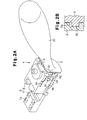
- the lever switch 1 includes a switch body 4, a case 2, and an insulator 3.
- the case 2 and the insulator 3 support the switch body 4.
- the switch body 4 includes a contact holder 5 and a lever 6.
- the contact holder 5 includes a connector 7 and a holder 8.
- connection holes 7a are formed in the upper surface of the connector 7. Connection terminals that extend from an external circuit (not shown) are respectively connected to the connection holes 7a to connect the lever switch 1 to the external circuit.
- the holder 8 rotatably supports the lever 6.
- the holder 8 is integrally formed with the connector 7.
- U-shaped slits 8a are respectively formed in the opposed sides of the holder 8.
- Each slit 8a forms a tab 8b.
- Each tab 8b has a pivot hole 8c.
- the tabs 8b support the lever 6.
- the lever 6 includes an actuator 9 and an arm 10.
- the arm 10 is integrally formed with the actuator 9.
- a couple of pivot joint shafts 9a respectively project from the sides of the actuator 9.
- the shafts 9a are rotatably supported by the corresponding pivot holes 8c.
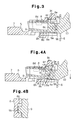
- a first main stopper 8d is formed on the lower surface of the upper wall of the holder 8.
- a recess 8e is formed near the entrance of the holder 8 (rightward of the first main stopper 8d in Fig. 3).
- the recess 8e is located above the pivot holes 8c.
- the first main stopper 8d is located on the opposite side (leftward in Fig. 3) of the pivot holes 8c from the arm 10.
- opposed notches 8g are formed in the entrance rim (right end in Fig. 3) of the holder 8.
- the notches 8g are located on the opposite side (rightward in Fig. 3) of the pivot holes 8c from the first main stopper 8d.
- a lower projection 8h which is a second main stopper, extends upward from the lower wall of the holder 8.
- the lower projection 8h is located below the pivot holes 8c in Fig. 3.
- a contact surface 8f is located near the center of the holder 8 in the longitudinal direction. The contact surface 8f extends from the left end surface of the recess 8e toward the entrance (rightward in Fig. 5B).
- a pair of horizontal projections 9b are respectively formed on the sides of the actuator 9.
- the projections 9b extend horizontally and parallel to the shafts 9a.
- the projections 9b are located in the corresponding notches 8g and can move in the notches 8g.
- the projections 9b and the notches 8g form a first auxiliary stopper.
- a vertical, or upper, projection 9c extends upward from the actuator 9 and is located in the recess 8e.
- the contact surface 8f and the upper projection 9c form a second auxiliary stopper.
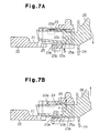
- the actuator 9 is pivoted about the shafts 9a when a force is manually applied to the arm 10. That is, the lever switch 1 is shifted between three positions, which include a neutral position shown in Fig. 3, a lower position shown in Fig. 4A, and an upper position shown in Fig. 5A.
- the upper surface of the actuator 9 contacts the first main stopper 8d and the projections 9b contact the lower surfaces of the notches 8g, which prevents further downward movement of the arm 10.
- downward forces F1 are applied to the shafts 9a from the inner surfaces of the pivot holes 8c as shown in Fig. 4A.
- the first main stopper 8d serves as a fulcrum for the forces Fl.
- upward forces F2 are applied to the shafts 9a from the inner surfaces of the pivot holes 8c.
- the lower surfaces of the notches 8g serve as fulcrums for the forces F2.
- F3 represents resultant forces of the downward forces F1 and the upward forces F2.
- the resultant forces F3 are smaller than the downward forces F1.
- the illustrated embodiment has the following advantages.
- the illustrated embodiment may further be varied as follows.
- projections 9b recesses may be formed.
- projections are formed on the holder 8 instead of the notches 8g.
- the arm 10 is lowered and the upper surface of the actuator 9 contacts the first main stopper 8d, the upper ends of such projections would contact the upper surfaces of the recesses of the actuator 9.
- the advantages are the same as those of the first embodiment.
- the upper projection 9c may be omitted.
- the notches 8g are preferably formed such that the upper walls of the notches 8g contact the upper surfaces of the projections 9b when the lever switch 1 is at the upper position.
- the projections 9b and the notches 8g serve as the first and second auxiliary stoppers.
- One of the projections 9b and the corresponding notch 8g may be omitted.
- Either the projections 9b or the upper projection 9c may be omitted.
- the lever 6 is not easily dislocated from the holder 5 compared to the prior art switches.
Landscapes
- Rotary Switch, Piano Key Switch, And Lever Switch (AREA)
- Switches With Compound Operations (AREA)
Abstract
Description
Claims (7)
- A lever switch (1) comprising:a holder (5); anda lever (6), which is pivotally supported by the holder through a pivot joint, the lever switch characterized by:a main stopper (8d, 8h), which is formed in the holder to limit the rotation of the lever to a certain position with respect to the holder; andan auxiliary stopper (8g, 9b, 8e, 8f, 9c), which limits the rotation of the lever to a certain position with respect to the holder in cooperation with the main stopper, wherein the auxiliary stopper is located on the opposite side of the pivot joint from the main stopper.
- The lever switch according to claim 1, characterized in that the auxiliary stopper includes a notch (8g) formed in the holder and a projection (9b) formed in the lever to correspond to the notch.
- A lever switch (1) comprising:a lever (6), which includes an arm (10) and an actuator (9);a holder (5), which holds the actuator;a pivot joint (9a) for supporting the lever to rotate with respect the holder, the lever switch characterized by:a main stopper (8d), which limits the rotation of the lever in a predetermined direction to a predetermined position; andan auxiliary stopper (8g, 9b), which is located on the opposite side of the pivot joint from the main stopper, wherein the auxiliary stopper limits the rotation of the lever in the predetermined direction to the predetermined position in cooperation with the main stopper.
- The lever switch according to claim 3, characterized in that the main stopper is formed in the holder and the actuator contacts the main stopper when the lever is at the first position.
- The lever switch according to claim 4, characterized in that the auxiliary stopper includes a projection (9b) formed in the lever and a notch (8g) formed in the holder, wherein the notch corresponds to the projection, and the projection and the notch are located closer to the arm than to the pivot joint.
- The lever switch according to any one of claims 3 to 5, wherein the main stopper is a first main stopper, the auxiliary stopper is a first auxiliary stopper, the predetermined direction is a first direction, and the predetermined position is a first position, the lever switch further characterized by:a second main stopper (8h), which limits the rotation of the lever in a second direction, which is opposite to the first direction, to a second position; anda second auxiliary stopper (8e, 8f, 9c), which is located on the opposite side of the pivot joint from the second main stopper, wherein the second auxiliary stopper limits the rotation of the lever in the second direction to the second position in cooperation with the second main stopper.
- The lever switch according to claim 3, characterized in that the lever extends in a generally longitudinal direction, wherein the actuator is located at one end of the lever, the arm being located at the other end of the lever, wherein the pivot joint is located between the arm and the actuator.
Applications Claiming Priority (2)
| Application Number | Priority Date | Filing Date | Title |
|---|---|---|---|
| JP00651499A JP3764290B2 (en) | 1999-01-13 | 1999-01-13 | Lever switch |
| JP651499 | 1999-01-13 |
Publications (3)
| Publication Number | Publication Date |
|---|---|
| EP1020884A2 true EP1020884A2 (en) | 2000-07-19 |
| EP1020884A3 EP1020884A3 (en) | 2001-09-05 |
| EP1020884B1 EP1020884B1 (en) | 2006-07-26 |
Family
ID=11640527
Family Applications (1)
| Application Number | Title | Priority Date | Filing Date |
|---|---|---|---|
| EP00100565A Expired - Lifetime EP1020884B1 (en) | 1999-01-13 | 2000-01-12 | Lever switch |
Country Status (5)
| Country | Link |
|---|---|
| US (1) | US6153842A (en) |
| EP (1) | EP1020884B1 (en) |
| JP (1) | JP3764290B2 (en) |
| KR (1) | KR100395287B1 (en) |
| DE (1) | DE60029498T2 (en) |
Cited By (1)
| Publication number | Priority date | Publication date | Assignee | Title |
|---|---|---|---|---|
| WO2005055261A1 (en) * | 2003-12-05 | 2005-06-16 | Valeo Schalter Und Sensoren Gmbh | Switch module |
Families Citing this family (4)
| Publication number | Priority date | Publication date | Assignee | Title |
|---|---|---|---|---|
| KR100331554B1 (en) * | 1999-09-27 | 2002-04-06 | 윤종용 | Capacitor array preventing crosstalk between adjacent capacitors in semiconductor device and method for fabricating the same |
| JP3875530B2 (en) * | 2001-10-03 | 2007-01-31 | 株式会社東海理化電機製作所 | Switch operation mechanism |
| KR100816994B1 (en) * | 2006-05-01 | 2008-03-27 | 주식회사 신창전기 | Multifunction switch lever |
| JP5036456B2 (en) * | 2007-09-03 | 2012-09-26 | オムロンオートモーティブエレクトロニクス株式会社 | Switch device |
Family Cites Families (6)
| Publication number | Priority date | Publication date | Assignee | Title |
|---|---|---|---|---|
| US4328431A (en) * | 1978-12-09 | 1982-05-04 | Kabushiki Kaisha Tokai Rika Denki Seisakusho | Lever switch |
| US4291213A (en) * | 1980-09-22 | 1981-09-22 | Deere & Company | Lever operator switch actuator |
| DE3118214C2 (en) * | 1981-05-08 | 1983-02-03 | Fa. Leopold Kostal, 5880 Lüdenscheid | Steering column switch |
| DE4016773C2 (en) * | 1990-05-25 | 1999-08-19 | Teves Gmbh Alfred | Electrical switch, in particular for operating a windshield wiper and a windshield washer system of a motor vehicle |
| JP2565582Y2 (en) * | 1990-07-18 | 1998-03-18 | 株式会社東海理化電機製作所 | Lever switch |
| US5600110A (en) * | 1992-06-11 | 1997-02-04 | Itt Automotive Europe Gmbh | Wear-resistant steering column switch with lever pivotable about two mutually parallel axes |
-
1999
- 1999-01-13 JP JP00651499A patent/JP3764290B2/en not_active Expired - Lifetime
- 1999-12-21 US US09/469,968 patent/US6153842A/en not_active Expired - Lifetime
-
2000
- 2000-01-12 KR KR10-2000-0001360A patent/KR100395287B1/en not_active Expired - Lifetime
- 2000-01-12 EP EP00100565A patent/EP1020884B1/en not_active Expired - Lifetime
- 2000-01-12 DE DE60029498T patent/DE60029498T2/en not_active Expired - Lifetime
Cited By (1)
| Publication number | Priority date | Publication date | Assignee | Title |
|---|---|---|---|---|
| WO2005055261A1 (en) * | 2003-12-05 | 2005-06-16 | Valeo Schalter Und Sensoren Gmbh | Switch module |
Also Published As
| Publication number | Publication date |
|---|---|
| EP1020884B1 (en) | 2006-07-26 |
| JP3764290B2 (en) | 2006-04-05 |
| EP1020884A3 (en) | 2001-09-05 |
| KR20000053464A (en) | 2000-08-25 |
| US6153842A (en) | 2000-11-28 |
| KR100395287B1 (en) | 2003-08-21 |
| JP2000208000A (en) | 2000-07-28 |
| DE60029498T2 (en) | 2006-12-28 |
| DE60029498D1 (en) | 2006-09-07 |
Similar Documents
| Publication | Publication Date | Title |
|---|---|---|
| EP1168514B1 (en) | Connector excellent in reliability of contact | |
| JP2976327B2 (en) | connector | |
| US5975929A (en) | Slidably fitting type connector | |
| JPH06325660A (en) | Microswitch | |
| EP1020884B1 (en) | Lever switch | |
| JPH10177824A (en) | Push-on switch | |
| US6711816B2 (en) | Method of manufacturing electrical connector for flat cable | |
| EP0262509A1 (en) | Seesaw switch | |
| US5018981A (en) | Contact equipped with a bypass element | |
| US5924556A (en) | Push switch device | |
| JP2692055B2 (en) | Electrical connector for flexible board | |
| JPH01500941A (en) | Switches, especially automotive steering column switches | |
| JP2006032285A (en) | Socket | |
| US20240145971A1 (en) | Electrical connector and switching device | |
| US4843195A (en) | Switch having dust-proof cover | |
| JP3098944B2 (en) | Electrical connector for flexible board | |
| JP3384676B2 (en) | Connector connection structure | |
| JP7538004B2 (en) | Microswitch | |
| US5099095A (en) | Lever switch device | |
| JP7565759B2 (en) | Microswitch | |
| US5086199A (en) | Lever switch | |
| JP2814447B2 (en) | Electrical connector for flexible board | |
| US7288735B2 (en) | Switching device | |
| JP3172667B2 (en) | Seesaw switch | |
| JPH0589926A (en) | Low inserting force connector |
Legal Events
| Date | Code | Title | Description |
|---|---|---|---|
| PUAI | Public reference made under article 153(3) epc to a published international application that has entered the european phase |
Free format text: ORIGINAL CODE: 0009012 |
|
| AK | Designated contracting states |
Kind code of ref document: A2 Designated state(s): AT BE CH CY DE DK ES FI FR GB GR IE IT LI LU MC NL PT SE |
|
| AX | Request for extension of the european patent |
Free format text: AL;LT;LV;MK;RO;SI |
|
| PUAL | Search report despatched |
Free format text: ORIGINAL CODE: 0009013 |
|
| AK | Designated contracting states |
Kind code of ref document: A3 Designated state(s): AT BE CH CY DE DK ES FI FR GB GR IE IT LI LU MC NL PT SE |
|
| AX | Request for extension of the european patent |
Free format text: AL;LT;LV;MK;RO;SI |
|
| RIC1 | Information provided on ipc code assigned before grant |
Free format text: 7H 01H 21/02 A, 7H 01H 21/22 B, 7B 60Q 1/14 B |
|
| 17P | Request for examination filed |
Effective date: 20011122 |
|
| AKX | Designation fees paid |
Free format text: DE FR GB |
|
| GRAP | Despatch of communication of intention to grant a patent |
Free format text: ORIGINAL CODE: EPIDOSNIGR1 |
|
| RIN1 | Information on inventor provided before grant (corrected) |
Inventor name: SATO, NAOKIC/O K. K. TOKAI RIKA DENKI SEISAKUSHO |
|
| GRAS | Grant fee paid |
Free format text: ORIGINAL CODE: EPIDOSNIGR3 |
|
| GRAA | (expected) grant |
Free format text: ORIGINAL CODE: 0009210 |
|
| AK | Designated contracting states |
Kind code of ref document: B1 Designated state(s): DE FR GB |
|
| REG | Reference to a national code |
Ref country code: GB Ref legal event code: FG4D |
|
| REF | Corresponds to: |
Ref document number: 60029498 Country of ref document: DE Date of ref document: 20060907 Kind code of ref document: P |
|
| ET | Fr: translation filed | ||
| PLBE | No opposition filed within time limit |
Free format text: ORIGINAL CODE: 0009261 |
|
| STAA | Information on the status of an ep patent application or granted ep patent |
Free format text: STATUS: NO OPPOSITION FILED WITHIN TIME LIMIT |
|
| 26N | No opposition filed |
Effective date: 20070427 |
|
| REG | Reference to a national code |
Ref country code: FR Ref legal event code: PLFP Year of fee payment: 17 |
|
| REG | Reference to a national code |
Ref country code: FR Ref legal event code: PLFP Year of fee payment: 18 |
|
| REG | Reference to a national code |
Ref country code: FR Ref legal event code: PLFP Year of fee payment: 19 |
|
| PGFP | Annual fee paid to national office [announced via postgrant information from national office to epo] |
Ref country code: FR Payment date: 20181213 Year of fee payment: 20 |
|
| PGFP | Annual fee paid to national office [announced via postgrant information from national office to epo] |
Ref country code: GB Payment date: 20190109 Year of fee payment: 20 Ref country code: DE Payment date: 20190102 Year of fee payment: 20 |
|
| REG | Reference to a national code |
Ref country code: DE Ref legal event code: R071 Ref document number: 60029498 Country of ref document: DE |
|
| REG | Reference to a national code |
Ref country code: GB Ref legal event code: PE20 Expiry date: 20200111 |
|
| PG25 | Lapsed in a contracting state [announced via postgrant information from national office to epo] |
Ref country code: GB Free format text: LAPSE BECAUSE OF EXPIRATION OF PROTECTION Effective date: 20200111 |