EP1020750A2 - Tension member-holder of overhead optical cable - Google Patents
Tension member-holder of overhead optical cable Download PDFInfo
- Publication number
- EP1020750A2 EP1020750A2 EP00100156A EP00100156A EP1020750A2 EP 1020750 A2 EP1020750 A2 EP 1020750A2 EP 00100156 A EP00100156 A EP 00100156A EP 00100156 A EP00100156 A EP 00100156A EP 1020750 A2 EP1020750 A2 EP 1020750A2
- Authority
- EP
- European Patent Office
- Prior art keywords
- tension member
- slit
- cross
- holder
- section
- Prior art date
- Legal status (The legal status is an assumption and is not a legal conclusion. Google has not performed a legal analysis and makes no representation as to the accuracy of the status listed.)
- Withdrawn
Links
Images






Classifications
-
- G—PHYSICS
- G02—OPTICS
- G02B—OPTICAL ELEMENTS, SYSTEMS OR APPARATUS
- G02B6/00—Light guides; Structural details of arrangements comprising light guides and other optical elements, e.g. couplings
- G02B6/44—Mechanical structures for providing tensile strength and external protection for fibres, e.g. optical transmission cables
- G02B6/4439—Auxiliary devices
- G02B6/4471—Terminating devices ; Cable clamps
- G02B6/4477—Terminating devices ; Cable clamps with means for strain-relieving to interior strengths element
Definitions
- the invention relates to a tension member-holder suited for a work for fitting tension members of an overhead optical cable in their right places.
- a fixing sleeve shown in Fig. 1 has been used in case that tension members of an overhead optical cable is fixed.
- a sleeve body 20 of a fixing sleeve is provided with fixing holes 21 and fixing screws 24.
- the tension members 23 of the overhead optical cable are fixed to the sleeve body 20, the tension members 23 are made to pass through the fixing holes 21, and the fixing screws 24 are driven.
- a tension member-holder for fixing one or more tension members of an overhead optical cable comprising one or more tension member-holding units, each of which comprises:
- a cross-section of a tension member-supporting channel may be triangular.
- a cross-section of a tension member-supporting channel may be rounded.
- a width of a slit is slightly smaller than a diameter of a tension member.
- a lower part of a cross-section of a periphery of a slit may be rounded.
- a lower part of a cross-section of a periphery of a slit may be tapered.
- An upper part of a cross-section of a periphery of a slit may be rounded.
- An upper part of a cross-section of a periphery of a slit may be tapered.
- tension members are made to pass through slits respectively excised on tension member-holding units in a longitudinal direction, and supported by tension member-holding channels.
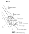
- Fig. 2 is a perspective view for showing a tension member-holder according to the first preferred embodiment.
- Fig. 3 is an enlarged perspective view for showing the tension member-holder shown in Fig. 2.
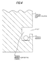
- Fig. 4 is a cross sectional view for showing an important part of the tension member-holder shown in Fig. 3
- Fig. 5 is a perspective view for explaining a method for holding the tension member by means of the tension member-holder shown in Fig. 2.
- a fixing sleeve 1 serving as a key part of the tension member-holder shown in Figs. 2 to 4 is provided with two tension member-holding units 2. Moreover, an insertion channel 3 is provided between the adjacent tension member-holding units 2, and an optical fiber cable 12 is inserted into the insertion channel 3.
- the tension member-holding unit 2 is provided with a slit 4 excised in a longitudinal direction on the fixing sleeve 1 and a tension member-supporting channel 5.
- the optical fiber 12 and the tension members 11 are taken out from the overhead optical cable 10 in the first place. Next, the tension members 11 are made to pass through the slits 4 of the tension member-holding units 2 and supported by the tension member-supporting channels 5.
- the tension members 11 can pass through the slits 4 in condition that the overhead optical cable 10 has excess lengths 11a of the tension members 11, the tension members 11 can be easily fitted to the tension member-holding channels 5.
- the tension members 11 are fitted to the tension member-holding channels 5, the tension members 11 are fixed to the tension member-holding units 2 of the fixing sleeve 1 by driving the fixing screw 6.
- the tension members 11 are supported by the tension member-supporting channels 5 after the tension members 11 have passed through the slits 4 formed on the tension member holding-units 2 of the fixing sleeve 1 in the longitudinal direction, the work for fitting the tension members 11 in their right places can be performed easily and certainly.
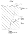
- Fig. 6 is a cross-sectional view for showing the second preferred embodiment of the invention in which the shape of the cross-section of the tension member-supporting channel 5 shown in Fig. 4 is changed.
- the cross-section of the tension member-supporting channel 5a is triangular.
- the tension member 11 which has passed through the slit 4 is supported by an inclined surface 5b and a vertical surface 5c, the tension member-supporting channel 5a can be made small-sized.
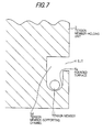
- Fig. 7 is a cross-sectional view for showing the third preferred embodiment of the invention in which the shape of the cross-section of the tension member-supporting channel 5 shown in Fig. 4 is changed.
- the cross-section of the tension member-supporting channel 5d is rounded.
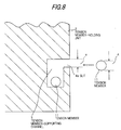
- Fig. 8 is a cross-sectional view for showing the fourth preferred embodiment of the invention in which a shape of a cross-section of the periphery of the slit 4 shown in Fig. 4 is changed.
- a width a of the slit 4a is slightly smaller than a diameter A of the tension member 11.
- the tension member 11 supported by the tension member-supporting channel 5 can be prevented from falling off.
- Fig. 9 is a cross-sectional view for showing the fifth preferred embodiment of the invention in which the shape of the cross-section of the periphery of the slit 4a shown in Fig. 8 is changed.
- a width a of the slit 4b is slightly smaller than a diameter A of the tension member 11 similarly to the fourth preferred embodiment.
- a lower part 4c of the cross-section of the periphery of the slit 4b is rounded.
- Fig. 10 is a cross-sectional view for showing the sixth preferred embodiment of the invention in which the shape of the cross-section of the periphery of the slit 4b in Fig. 9 is changed.
- a width a of a slit 4d is slightly smaller than the diameter A of the tension member 11 similarly to the fifth preferred embodiment.
- a lower part 4e of the cross-section of the periphery of the slit 4d is tapered.
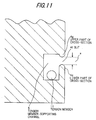
- Fig. 11 shows the seventh preferred embodiment of the invention in which the shape of the cross-section of the periphery of the slit 4b in Fig. 9 is changed.
- a width a of a slit 4f is slightly smaller than the diameter A of the tension member 11 similarly to the fifth preferred embodiment.
- an upper part 4g of a cross-section of the periphery of the slit 4f is rounded similarly to the lower part 4e of the same.
- both the upper and lower parts 4g and 4e of the cross-section of the periphery of the slit 4f are rounded in addition to the effect of the fifth preferred embodiment, the tension member 11 can pass through the slit 4f more easily.
- Fig. 12 is a cross-sectional view for showing the eighth preferred embodiment of the invention in which the shape of the cross-section of the periphery of the slit 4d in Fig. 10 is changed.
- a width a of a slit 4h is slightly smaller than the diameter A of the tension member 11.
- an upper part 4i of the cross-section of the periphery of the slit 4h is tapered similarly to the lower part 4e of the same.
- both the upper and lower parts 4i and 4e of the cross-section of the periphery of the slit 4h are tapered in addition to the effect of the sixth preferred embodiment, the tension member 11 can pass through the slit 4h more easily.
- the tension member-holder since the tension members are made to pass through slits respectively excised on the tension member-holding units in the longitudinal direction and supported by the tension member-holding channels, the work for fitting the tension members in their right places can be performed easily and certainly.
Landscapes
- Physics & Mathematics (AREA)
- General Physics & Mathematics (AREA)
- Optics & Photonics (AREA)
- Suspension Of Electric Lines Or Cables (AREA)
- Mechanical Coupling Of Light Guides (AREA)
- Light Guides In General And Applications Therefor (AREA)
Abstract
Description
Claims (8)
- A tension member-holder for fixing one or more tension members of an overhead optical cable comprising one or more tension member-holding units, each of which comprises:a slit formed thereon in a longitudinal direction, said tension member passing through said slit,a tension member-supporting channel communicated with said slit, anda fixing screw for fixing said tension member to said tension member-supporting channel.
- A tension member-holder defined as claim 1, wherein:a cross-section of said tension member-supporting channel is triangular.
- A tension member-holder defined as claim 1, wherein:a cross-section of said tension member-supporting channel is rounded.
- The tension member-holder as defined in any of claims 1 to 3, wherein:a width of said slit is slightly smaller than a diameter of said tension member.
- The tension member-holder as defined in any of claims 1 to 4, wherein:a lower part of a cross-section of a periphery of said slit is rounded.
- The tension member-holder as defined in any of claims 1 to 4, wherein:a lower part of a cross-section of a periphery of said slit is tapered.
- The tension member-holder as defined in any of claims 1 to 6, wherein:a upper part of a cross-section of a periphery of said slit is rounded.
- The tension member-holder as defined in any of claims 1 to 6, wherein: a upper part of a cross-section of a periphery of said slit is tapered.
Applications Claiming Priority (2)
| Application Number | Priority Date | Filing Date | Title |
|---|---|---|---|
| JP11004603A JP2000206358A (en) | 1999-01-11 | 1999-01-11 | Tension member holding device |
| JP460399 | 1999-01-11 |
Publications (2)
| Publication Number | Publication Date |
|---|---|
| EP1020750A2 true EP1020750A2 (en) | 2000-07-19 |
| EP1020750A3 EP1020750A3 (en) | 2000-10-11 |
Family
ID=11588626
Family Applications (1)
| Application Number | Title | Priority Date | Filing Date |
|---|---|---|---|
| EP00100156A Withdrawn EP1020750A3 (en) | 1999-01-11 | 2000-01-11 | Tension member-holder of overhead optical cable |
Country Status (3)
| Country | Link |
|---|---|
| EP (1) | EP1020750A3 (en) |
| JP (1) | JP2000206358A (en) |
| SG (1) | SG83176A1 (en) |
Cited By (6)
| Publication number | Priority date | Publication date | Assignee | Title |
|---|---|---|---|---|
| WO2012058275A2 (en) | 2010-10-26 | 2012-05-03 | Adc Telecommunications, Inc. | System and method for anchoring fiber optic cables to provide strain relief |
| WO2019034613A1 (en) * | 2017-08-15 | 2019-02-21 | CommScope Connectivity Belgium BVBA | Cable fixation assembly for a cable having a strength member |
| FR3078411A1 (en) * | 2018-02-28 | 2019-08-30 | Telenco Networks | TIGHTENING MEMBER FOR OPTICAL FIBER CABLE |
| US11841543B2 (en) | 2019-04-22 | 2023-12-12 | Commscope Technologies Llc | Cable fixation assembly with improved strength member yarn anchoring and method of anchoring cable strength member yarn |
| US11867872B2 (en) | 2020-02-11 | 2024-01-09 | Commscope Technologies Llc | Cable fixation devices and arrangements with improved installation and space utilization at telecommunications enclosures |
| US12210204B2 (en) | 2019-01-22 | 2025-01-28 | Commscope Technologies Llc | Cable fixation assemblies for telecommunications enclosures |
Families Citing this family (1)
| Publication number | Priority date | Publication date | Assignee | Title |
|---|---|---|---|---|
| JP4732855B2 (en) * | 2005-10-31 | 2011-07-27 | ミハル通信株式会社 | Tensile wire fixing device |
Family Cites Families (2)
| Publication number | Priority date | Publication date | Assignee | Title |
|---|---|---|---|---|
| JPS6015609A (en) * | 1983-07-08 | 1985-01-26 | Nippon Telegr & Teleph Corp <Ntt> | Mechanical connecting structure for juncture of optical cable |
| FR2769377B1 (en) * | 1997-10-07 | 2000-11-24 | France Telecom | OPTICAL FIBER PICKING BOX IN A FIBER OPTIC CABLE |
-
1999
- 1999-01-11 JP JP11004603A patent/JP2000206358A/en active Pending
-
2000
- 2000-01-05 SG SG200000069A patent/SG83176A1/en unknown
- 2000-01-11 EP EP00100156A patent/EP1020750A3/en not_active Withdrawn
Cited By (9)
| Publication number | Priority date | Publication date | Assignee | Title |
|---|---|---|---|---|
| WO2012058275A2 (en) | 2010-10-26 | 2012-05-03 | Adc Telecommunications, Inc. | System and method for anchoring fiber optic cables to provide strain relief |
| EP2633356A4 (en) * | 2010-10-26 | 2014-04-09 | Adc Telecommunications Inc | SYSTEM AND METHOD FOR ANCHORING OPTICAL FIBER CABLES TO PROVIDE RELAXATION |
| WO2019034613A1 (en) * | 2017-08-15 | 2019-02-21 | CommScope Connectivity Belgium BVBA | Cable fixation assembly for a cable having a strength member |
| US11163130B2 (en) | 2017-08-15 | 2021-11-02 | CommScope Connectivity Belgium BVBA | Cable fixation assembly for a cable having a strength member |
| FR3078411A1 (en) * | 2018-02-28 | 2019-08-30 | Telenco Networks | TIGHTENING MEMBER FOR OPTICAL FIBER CABLE |
| US12210204B2 (en) | 2019-01-22 | 2025-01-28 | Commscope Technologies Llc | Cable fixation assemblies for telecommunications enclosures |
| US11841543B2 (en) | 2019-04-22 | 2023-12-12 | Commscope Technologies Llc | Cable fixation assembly with improved strength member yarn anchoring and method of anchoring cable strength member yarn |
| US11867872B2 (en) | 2020-02-11 | 2024-01-09 | Commscope Technologies Llc | Cable fixation devices and arrangements with improved installation and space utilization at telecommunications enclosures |
| US12292612B2 (en) | 2020-02-11 | 2025-05-06 | Commscope Technologies Llc | Cable fixation devices and arrangements with improved installation and space utilization at telecommunications enclosures |
Also Published As
| Publication number | Publication date |
|---|---|
| JP2000206358A (en) | 2000-07-28 |
| EP1020750A3 (en) | 2000-10-11 |
| SG83176A1 (en) | 2001-09-18 |
Similar Documents
| Publication | Publication Date | Title |
|---|---|---|
| US11428884B2 (en) | Fibre optic accessory | |
| EP0838230A3 (en) | Guide wire | |
| EP1255144A3 (en) | Dividable optical cable | |
| EP1139127A3 (en) | Apparatus and method for assembling and aligning a plurality of optical fibers | |
| EP1020750A2 (en) | Tension member-holder of overhead optical cable | |
| EP0616372A3 (en) | DMOS short channel transistor with trench. | |
| EP1197610A3 (en) | Longitudinal facing, facing retainers, and facing structure having facing and facing retainers | |
| EP0940362A3 (en) | Wire transfer assembly | |
| BR9904695B1 (en) | process for the continuous fabrication of a composite tube and device for performing the process. | |
| JPH04291215A (en) | Strain relief for fiber optic cables | |
| EP1321783B1 (en) | Optical fiber fixing structure | |
| DE60208811T2 (en) | ARRANGEMENT WITH A JACK AND A CONNECTOR FOR OPTICAL FIBERS | |
| DE60219183T2 (en) | METHOD AND DEVICE FOR SMOOTING GLASS FIBERS | |
| DE50106727D1 (en) | feed | |
| WO2003041569A3 (en) | Graft and method of making | |
| DE19921351A1 (en) | Cable cord mounting arrangement e.g. for vehicle chassis | |
| US6131991A (en) | Wire harness layout arrangement for automobile back door | |
| FR2718287B1 (en) | Method for manufacturing an insulated gate field effect transistor, in particular of reduced channel length, and corresponding transistor. | |
| US6413116B2 (en) | Insulation-displacement connection piece | |
| EP1653136A3 (en) | Snap-on cable retainer | |
| AU767626B2 (en) | Break-out device | |
| BR0115863B1 (en) | process for producing a cable provided with at least one thermoplastic sheath. | |
| BR9916664B1 (en) | A process for producing a tube of polymeric material associated with at least one optical fiber accommodated therein, tube of polymeric material, and equipment for producing a tube comprising at least one optical fiber accommodated therein. | |
| FR2717718B1 (en) | Method for manufacturing a pulley with multiple grooves, forming tool implemented by this method and pulley thus obtained. | |
| FR2717513B1 (en) | Method of manufacturing a slot channel. |
Legal Events
| Date | Code | Title | Description |
|---|---|---|---|
| PUAI | Public reference made under article 153(3) epc to a published international application that has entered the european phase |
Free format text: ORIGINAL CODE: 0009012 |
|
| AK | Designated contracting states |
Kind code of ref document: A2 Designated state(s): DE NL |
|
| AX | Request for extension of the european patent |
Free format text: AL;LT;LV;MK;RO;SI |
|
| PUAL | Search report despatched |
Free format text: ORIGINAL CODE: 0009013 |
|
| AK | Designated contracting states |
Kind code of ref document: A3 Designated state(s): AT BE CH CY DE DK ES FI FR GB GR IE IT LI LU MC NL PT SE |
|
| AX | Request for extension of the european patent |
Free format text: AL;LT;LV;MK;RO;SI |
|
| RIC1 | Information provided on ipc code assigned before grant |
Free format text: 7G 02B 6/44 A, 7G 02B 6/38 B, 7H 01R 9/22 B |
|
| 17P | Request for examination filed |
Effective date: 20000830 |
|
| AKX | Designation fees paid |
Free format text: DE NL |
|
| STAA | Information on the status of an ep patent application or granted ep patent |
Free format text: STATUS: THE APPLICATION HAS BEEN WITHDRAWN |
|
| 18W | Application withdrawn |
Withdrawal date: 20020823 |