EP1020716A2 - Method and apparatus for torque measurement - Google Patents
Method and apparatus for torque measurement Download PDFInfo
- Publication number
- EP1020716A2 EP1020716A2 EP00300221A EP00300221A EP1020716A2 EP 1020716 A2 EP1020716 A2 EP 1020716A2 EP 00300221 A EP00300221 A EP 00300221A EP 00300221 A EP00300221 A EP 00300221A EP 1020716 A2 EP1020716 A2 EP 1020716A2
- Authority
- EP
- European Patent Office
- Prior art keywords
- wave
- waves
- shaft
- torque
- pulses
- Prior art date
- Legal status (The legal status is an assumption and is not a legal conclusion. Google has not performed a legal analysis and makes no representation as to the accuracy of the status listed.)
- Granted
Links
- 238000000034 method Methods 0.000 title claims abstract description 25
- 238000005259 measurement Methods 0.000 title abstract description 14
- 230000000644 propagated effect Effects 0.000 claims description 3
- 230000000694 effects Effects 0.000 abstract description 22
- 239000000463 material Substances 0.000 description 15
- 230000003068 static effect Effects 0.000 description 13
- 230000001902 propagating effect Effects 0.000 description 6
- 238000012360 testing method Methods 0.000 description 5
- 230000001066 destructive effect Effects 0.000 description 3
- 230000003287 optical effect Effects 0.000 description 3
- 230000000737 periodic effect Effects 0.000 description 3
- 239000007787 solid Substances 0.000 description 3
- 238000005452 bending Methods 0.000 description 2
- 230000001419 dependent effect Effects 0.000 description 2
- 238000001514 detection method Methods 0.000 description 2
- 238000006073 displacement reaction Methods 0.000 description 2
- 238000011156 evaluation Methods 0.000 description 2
- 238000004519 manufacturing process Methods 0.000 description 2
- 229910000831 Steel Inorganic materials 0.000 description 1
- 230000001934 delay Effects 0.000 description 1
- 238000011161 development Methods 0.000 description 1
- 238000002474 experimental method Methods 0.000 description 1
- 230000001939 inductive effect Effects 0.000 description 1
- 238000011089 mechanical engineering Methods 0.000 description 1
- 229910021645 metal ion Inorganic materials 0.000 description 1
- 238000012986 modification Methods 0.000 description 1
- 230000004048 modification Effects 0.000 description 1
- 230000010363 phase shift Effects 0.000 description 1
- 230000002441 reversible effect Effects 0.000 description 1
- 125000006850 spacer group Chemical group 0.000 description 1
- 239000010959 steel Substances 0.000 description 1
- 230000002277 temperature effect Effects 0.000 description 1
Images


Classifications
-
- G—PHYSICS
- G01—MEASURING; TESTING
- G01L—MEASURING FORCE, STRESS, TORQUE, WORK, MECHANICAL POWER, MECHANICAL EFFICIENCY, OR FLUID PRESSURE
- G01L3/00—Measuring torque, work, mechanical power, or mechanical efficiency, in general
- G01L3/02—Rotary-transmission dynamometers
- G01L3/04—Rotary-transmission dynamometers wherein the torque-transmitting element comprises a torsionally-flexible shaft
- G01L3/10—Rotary-transmission dynamometers wherein the torque-transmitting element comprises a torsionally-flexible shaft involving electric or magnetic means for indicating
-
- G—PHYSICS
- G01—MEASURING; TESTING
- G01L—MEASURING FORCE, STRESS, TORQUE, WORK, MECHANICAL POWER, MECHANICAL EFFICIENCY, OR FLUID PRESSURE
- G01L1/00—Measuring force or stress, in general
- G01L1/25—Measuring force or stress, in general using wave or particle radiation, e.g. X-rays, microwaves, neutrons
- G01L1/255—Measuring force or stress, in general using wave or particle radiation, e.g. X-rays, microwaves, neutrons using acoustic waves, or acoustic emission
Definitions
- the measurement of torque provides information on the forces acting on static structural members, the friction between one moving and one static structural member, or the power transmitted via rotating members. This information makes it possible to control the performance of a great variety of mechanical tools and machines in terms of efficiency and reliability.
- Thompson discloses a system whereby residual stress in a flat plate is measured by comparing the velocities of two horizontally (i.e. parallel to the surface of the plate being tested) polarised and horizontally propagating shear waves with inter-changed directions of propagation and polarisation.
- the apparatus disclosed in Thompson comprises two periodic permanent magnet-electromagnetic acoustic transducers separated by and fixed to a spacer bar of known length. One of the transducers is arranged to transmit an ultrasonic shear wave along the line connecting the two transducers whereas the other transducer detects the wave transmitted by the first transducer.
- a single wave of no specific polarisation can be generated.
- Such a wave would be a wave of mixed polarisation or a radially polarised wave (i.e. a wave having all transverse polarisations)
- the birefringence effect then means that this wave is split into two component orthogonally polarised waves or wave pulses 3.
- These component wave pulses are polarised in directions parallel to each of the two axes 1,2 of principal stress to which the shaft is subjected and are therefore sensitive to these stresses.
- a single pulse being polarised in such a way that its polarisation can be described as a superposition of two pulses 3 having transverse polarisation, orthogonal with respect to each other, will split into two separate pulses having orthogonal polarisation with respect to each other when travelling along the diameter and having different velocities of propagation.
- This will give rise to a time delay between the two pulses when travelling a predetermined distance.
- the time delay is a function of the torsional stresses in the shaft, and therefore of the applied torque.
- the time difference is a function of the applied torque.
- the transducer might be of the order of a few centimetres in circumference and the acoustic pulses take a matter of microseconds to make their journey.
- the time delay between reception of the reflected pulses is of the order of nanoseconds which is detectable and measurable. The time delay increases continuously with increasing torque.
- acoustic waves could be generated by a pulsed laser source, similarly spaced from the shaft, or else by a piezoelectric transducer mounted on the shaft.
- a difference in their acoustic velocities arises if the pulses travel along propagation paths which experience different stresses.
- two shear horizontal or SH acoustic wave pulses i.e. wave pulses whose direction of polarisation is parallel to the surface of the shaft
- the detected time delay is a function of the torsional stress in the shaft, and therefore of the applied torque.
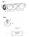
- FIG 4 shows an embodiment of the invention in which transverse shear horizontal acoustic wave pulses are deployed parallel to and just below (or along) a cylindrical surface of the shaft.
- a first EMAT 14 is used to generate the pulses 5 which propagate along the helical principal directions 1,2 of stress on the surface of the shaft.
- a second EMAT 16 positioned further along the shaft at a point where the two helical propagation paths cross, detects the pulses and again the time delay due to applied stress can be measured.
- the torque applied to rotating shafts can be derived from the time delay between the pulses only if the rotation speed and direction of the shaft is known since the rotation speed will have an effect on the time delay.
Landscapes
- Physics & Mathematics (AREA)
- General Physics & Mathematics (AREA)
- Acoustics & Sound (AREA)
- Health & Medical Sciences (AREA)
- Toxicology (AREA)
- Force Measurement Appropriate To Specific Purposes (AREA)
- Investigating Or Analyzing Materials By The Use Of Ultrasonic Waves (AREA)
Abstract
Description
Claims (17)
- A method of measuring the torque transmitted by a torque bearing member (10) comprising generating two acoustic waves or wave pulses (3,5) travelling through at least part of the shaft, and/or along or near to the surface of the shaft, the propagation velocities of the waves or wave pulses being affected differently by stresses resulting from an applied torque, and measuring the difference in velocity of the waves or wave pulses.
- A method according to claim 1 wherein the difference in velocity is measured by determining the difference in time taken for the waves or wave pulses (3,5) to travel a predetermined distance.
- A method according to claim 1 or claim 2 wherein the two waves or wave pulses (3) have directions of polarisation which are orthogonal to each other.
- A method according to any of claims 1 to 3 wherein the two waves or wave pulses (5) have directions of propagation which are different to each other.
- A method according to claim 4 wherein the two waves or wave pulses are both propagated along the surface of the shaft (10) in directions other than parallel or orthogonal to the longitudinal axis of the shaft.
- A method according to claim 4 or claim 5 wherein the two waves or wave pulses have directions of propagation which are orthogonal to each other.
- A method according to claim 6 wherein the two waves or wave pulses (5) (3) are propagated parallel to the surface of the shaft in directions (1,2) at substantially 45° to the longitudinal axis of the shaft.
- A method according to claim 3 wherein the two waves or wave pulses (3) have a common path which extends along a radius or part of a radius of the shaft.
- A method according to claim 8 comprising generating a single wave or wave pulse which splits into two orthogonally polarised component waves or wave pulses (3), said component waves or wave pulses forming the said two waves or wave pulses having directions of polarisation which are orthogonal to each other.
- Torque measuring apparatus for measuring the torque transmitted by a torque transmitting member, the apparatus comprising a wave generator or wave generators (12, 14, 18) for generating two acoustic waves or wave pulses (3,5) through at least part of the shaft or along the surface of the shaft (10) and means for measuring the difference in time taken for the waves or wave pulses to travel a predetermined distance.
- Apparatus according to claim 10 wherein the wave generator (12) comprises means for generating two waves or wave pulses having directions of polarisation which are orthogonal to each other.
- Apparatus according to claim 10 or 11 wherein the wave generator (14,18) comprises means for generating two waves or wave pulses having directions of propagation which are different from each other.
- Apparatus according to claim 12 wherein the wave generator (14,18) comprises means for generating two waves or wave pulses having directions (1,2) of propagation which are orthogonal to each other.
- Apparatus according to claim 11 wherein the wave generator comprises means for generating two waves or wave pulses (3) having a common path.
- Apparatus according to any of claims 10 to 14 further comprising a wave detector or wave detectors (12, 16, 22) for detecting the waves generated by the wave generator or generators, and a timing circuit for measuring the difference in time taken for the waves or wave pulses to travel from the wave generator or generators to the wave detector or detectors.
- Apparatus according to any of claims 10 to 15 wherein a wave generator is one of an electromagnetic acoustic transducer, a piezoelectric transduces or a pulsed laser source.
- Apparatus according to claim 16 wherein a wave detector is an electromagnetic acoustic transducer or a piezoelectric transducer.
Applications Claiming Priority (2)
| Application Number | Priority Date | Filing Date | Title |
|---|---|---|---|
| GB9900706 | 1999-01-13 | ||
| GB9900706A GB2345755A (en) | 1999-01-13 | 1999-01-13 | Method and apparatus for torque measurement |
Publications (3)
| Publication Number | Publication Date |
|---|---|
| EP1020716A2 true EP1020716A2 (en) | 2000-07-19 |
| EP1020716A3 EP1020716A3 (en) | 2000-12-20 |
| EP1020716B1 EP1020716B1 (en) | 2002-08-28 |
Family
ID=10845912
Family Applications (1)
| Application Number | Title | Priority Date | Filing Date |
|---|---|---|---|
| EP20000300221 Expired - Lifetime EP1020716B1 (en) | 1999-01-13 | 2000-01-13 | Method and apparatus for torque measurement |
Country Status (4)
| Country | Link |
|---|---|
| EP (1) | EP1020716B1 (en) |
| CA (1) | CA2295405C (en) |
| DE (1) | DE60000351T2 (en) |
| GB (1) | GB2345755A (en) |
Cited By (3)
| Publication number | Priority date | Publication date | Assignee | Title |
|---|---|---|---|---|
| USRE43960E1 (en) | 2007-01-11 | 2013-02-05 | Baker Hughes Incorporated | System for measuring stress in downhole tubulars |
| DE102013019955A1 (en) | 2013-11-27 | 2015-06-11 | Avl List Gmbh | Internal combustion engine |
| CN113074849A (en) * | 2021-03-26 | 2021-07-06 | 重庆交通大学 | Concrete surface absolute stress measuring method based on laser ultrasonic technology |
Families Citing this family (1)
| Publication number | Priority date | Publication date | Assignee | Title |
|---|---|---|---|---|
| DE102008002065B4 (en) | 2008-05-29 | 2017-03-09 | Zf Friedrichshafen Ag | Arrangement for contactless detection of a torque |
Family Cites Families (8)
| Publication number | Priority date | Publication date | Assignee | Title |
|---|---|---|---|---|
| US4080836A (en) * | 1977-03-07 | 1978-03-28 | Rockwell International Corporation | Method of measuring stress in a material |
| LU84553A1 (en) * | 1982-12-24 | 1984-10-22 | Benoit De Halleux | METHOD OF MEASURING CONSTRAINT IN A MEDIUM AND ELEMENT AND ASSEMBLY FOR IMPLEMENTING THE METHOD |
| US5170366A (en) * | 1989-10-30 | 1992-12-08 | Frank Passarelli | Apparatus for measuring load by propagation of an acoustic wave within a rigid structure |
| GB9004822D0 (en) * | 1990-03-03 | 1990-04-25 | Lonsdale Anthony | Method and apparatus for measuring torque |
| US5172591A (en) * | 1990-08-20 | 1992-12-22 | Atlantic Richfield Company | Oil well sucker rod load measurement |
| US5604314A (en) * | 1994-10-26 | 1997-02-18 | Bonneville Scientific Incorporated | Triaxial normal and shear force sensor |
| DE19781746T1 (en) * | 1996-05-03 | 1999-03-25 | Ultrafast Inc | Technique for eliminating or eliminating ambiguity when performing pulse-echo time or clock measurements |
| US5813280A (en) * | 1996-07-02 | 1998-09-29 | The United States Of America As Represented By The Secretary Of Commerce | Acoustic resonator for measuring force |
-
1999
- 1999-01-13 GB GB9900706A patent/GB2345755A/en not_active Withdrawn
-
2000
- 2000-01-13 DE DE2000600351 patent/DE60000351T2/en not_active Expired - Lifetime
- 2000-01-13 CA CA 2295405 patent/CA2295405C/en not_active Expired - Fee Related
- 2000-01-13 EP EP20000300221 patent/EP1020716B1/en not_active Expired - Lifetime
Cited By (3)
| Publication number | Priority date | Publication date | Assignee | Title |
|---|---|---|---|---|
| USRE43960E1 (en) | 2007-01-11 | 2013-02-05 | Baker Hughes Incorporated | System for measuring stress in downhole tubulars |
| DE102013019955A1 (en) | 2013-11-27 | 2015-06-11 | Avl List Gmbh | Internal combustion engine |
| CN113074849A (en) * | 2021-03-26 | 2021-07-06 | 重庆交通大学 | Concrete surface absolute stress measuring method based on laser ultrasonic technology |
Also Published As
| Publication number | Publication date |
|---|---|
| EP1020716A3 (en) | 2000-12-20 |
| DE60000351T2 (en) | 2003-04-17 |
| GB2345755A (en) | 2000-07-19 |
| CA2295405C (en) | 2008-01-08 |
| CA2295405A1 (en) | 2000-07-13 |
| EP1020716B1 (en) | 2002-08-28 |
| DE60000351D1 (en) | 2002-10-02 |
Similar Documents
| Publication | Publication Date | Title |
|---|---|---|
| US4080836A (en) | Method of measuring stress in a material | |
| Nagy et al. | Corrosion and erosion monitoring in plates and pipes using constant group velocity Lamb wave inspection | |
| US5813280A (en) | Acoustic resonator for measuring force | |
| Dixon et al. | High accuracy non-contact ultrasonic thickness gauging of aluminium sheet using electromagnetic acoustic transducers | |
| Kim et al. | Torsional wave experiments with a new magnetostrictive transducer configuration | |
| US6571632B1 (en) | Method and apparatus to provide dynamic ultrasonic measurement of rolling element bearing parameters | |
| KR100573736B1 (en) | Transducer capable of generating and measuring torsional waves, and an abnormal diagnosis device and method using the same | |
| WO2008086463A1 (en) | System for measuring stress in downhole tubulars | |
| Figueroa et al. | An ultrasonic ranging system for structural vibration measurements | |
| KR20050102516A (en) | Magnetostrictive transducer for generating and sensing elastic ultrasonic waves, and apparatus for structural diagnosis using it | |
| Knapp et al. | Measurement of shock events by means of strain gauges and accelerometers | |
| Thon et al. | Development of a linear array electromagnetic acoustic transducer for shear horizontal guided wave inspection | |
| Gachagan et al. | Generation and reception of ultrasonic guided waves in composite plates using conformable piezoelectric transmitters and optical-fiber detectors | |
| EP1020716B1 (en) | Method and apparatus for torque measurement | |
| US4712432A (en) | Torque sensor | |
| JP3299505B2 (en) | Ultrasonic flaw detection method using magnetostriction effect | |
| Lonsdale | Dynamic rotary torque measurement using surface acoustic waves | |
| Jassby et al. | Experimental technique for measurement of stress-acoustic coefficients of Rayleigh waves: An experimental technique is described for determining the two stress-acoustic coefficients relating Rayleight-wave velocity to biaxial surface stress in elastic solids. The method is applied to two aluminum alloys | |
| Ostachowicz et al. | Damage localisation using elastic waves propagation method. Experimental techniques | |
| RU2660770C1 (en) | Acoustical method of determination of elastic constants of current-conducting solids | |
| JP4465420B2 (en) | Magnetostrictive ultrasonic element and nondestructive inspection method using the same | |
| Liu et al. | Metal core piezoelectric ceramic fiber rosettes for acousto-ultrasonic source localization in plate structures | |
| Gnäupel-Herold et al. | A comparison of neutron and ultrasonic determinations of residual stress | |
| Ostachowicz et al. | Damage detection using laser vibrometry | |
| US9074860B2 (en) | Systems and methods for magnetostrictive sensing |
Legal Events
| Date | Code | Title | Description |
|---|---|---|---|
| PUAI | Public reference made under article 153(3) epc to a published international application that has entered the european phase |
Free format text: ORIGINAL CODE: 0009012 |
|
| AK | Designated contracting states |
Kind code of ref document: A2 Designated state(s): DE FR GB IT |
|
| AX | Request for extension of the european patent |
Free format text: AL;LT;LV;MK;RO;SI |
|
| PUAL | Search report despatched |
Free format text: ORIGINAL CODE: 0009013 |
|
| AK | Designated contracting states |
Kind code of ref document: A3 Designated state(s): AT BE CH CY DE DK ES FI FR GB GR IE IT LI LU MC NL PT SE |
|
| AX | Request for extension of the european patent |
Free format text: AL;LT;LV;MK;RO;SI |
|
| RIC1 | Information provided on ipc code assigned before grant |
Free format text: 7G 01L 3/10 A, 7G 01L 1/25 B, 7G 01L 5/00 B |
|
| 17P | Request for examination filed |
Effective date: 20010613 |
|
| 17Q | First examination report despatched |
Effective date: 20010720 |
|
| AKX | Designation fees paid |
Free format text: DE FR GB IT |
|
| GRAG | Despatch of communication of intention to grant |
Free format text: ORIGINAL CODE: EPIDOS AGRA |
|
| GRAG | Despatch of communication of intention to grant |
Free format text: ORIGINAL CODE: EPIDOS AGRA |
|
| GRAH | Despatch of communication of intention to grant a patent |
Free format text: ORIGINAL CODE: EPIDOS IGRA |
|
| GRAH | Despatch of communication of intention to grant a patent |
Free format text: ORIGINAL CODE: EPIDOS IGRA |
|
| GRAA | (expected) grant |
Free format text: ORIGINAL CODE: 0009210 |
|
| AK | Designated contracting states |
Kind code of ref document: B1 Designated state(s): DE FR GB IT |
|
| REG | Reference to a national code |
Ref country code: GB Ref legal event code: FG4D |
|
| REF | Corresponds to: |
Ref document number: 60000351 Country of ref document: DE Date of ref document: 20021002 |
|
| ET | Fr: translation filed | ||
| PLBE | No opposition filed within time limit |
Free format text: ORIGINAL CODE: 0009261 |
|
| STAA | Information on the status of an ep patent application or granted ep patent |
Free format text: STATUS: NO OPPOSITION FILED WITHIN TIME LIMIT |
|
| 26N | No opposition filed |
Effective date: 20030530 |
|
| REG | Reference to a national code |
Ref country code: GB Ref legal event code: 732E |
|
| REG | Reference to a national code |
Ref country code: GB Ref legal event code: 732E |
|
| REG | Reference to a national code |
Ref country code: FR Ref legal event code: CD Ref country code: FR Ref legal event code: TP Ref country code: FR Ref legal event code: CA |
|
| REG | Reference to a national code |
Ref country code: FR Ref legal event code: PLFP Year of fee payment: 17 |
|
| PGFP | Annual fee paid to national office [announced via postgrant information from national office to epo] |
Ref country code: FR Payment date: 20151208 Year of fee payment: 17 |
|
| PGFP | Annual fee paid to national office [announced via postgrant information from national office to epo] |
Ref country code: IT Payment date: 20160127 Year of fee payment: 17 Ref country code: DE Payment date: 20160105 Year of fee payment: 17 |
|
| PGFP | Annual fee paid to national office [announced via postgrant information from national office to epo] |
Ref country code: GB Payment date: 20160113 Year of fee payment: 17 |
|
| REG | Reference to a national code |
Ref country code: DE Ref legal event code: R119 Ref document number: 60000351 Country of ref document: DE |
|
| GBPC | Gb: european patent ceased through non-payment of renewal fee |
Effective date: 20170113 |
|
| REG | Reference to a national code |
Ref country code: FR Ref legal event code: ST Effective date: 20170929 |
|
| PG25 | Lapsed in a contracting state [announced via postgrant information from national office to epo] |
Ref country code: FR Free format text: LAPSE BECAUSE OF NON-PAYMENT OF DUE FEES Effective date: 20170131 |
|
| PG25 | Lapsed in a contracting state [announced via postgrant information from national office to epo] |
Ref country code: DE Free format text: LAPSE BECAUSE OF NON-PAYMENT OF DUE FEES Effective date: 20170801 Ref country code: GB Free format text: LAPSE BECAUSE OF NON-PAYMENT OF DUE FEES Effective date: 20170113 |
|
| PG25 | Lapsed in a contracting state [announced via postgrant information from national office to epo] |
Ref country code: IT Free format text: LAPSE BECAUSE OF NON-PAYMENT OF DUE FEES Effective date: 20170113 |