EP1020625A2 - Intake air control system of internal combustion engine - Google Patents
Intake air control system of internal combustion engine Download PDFInfo
- Publication number
- EP1020625A2 EP1020625A2 EP00100452A EP00100452A EP1020625A2 EP 1020625 A2 EP1020625 A2 EP 1020625A2 EP 00100452 A EP00100452 A EP 00100452A EP 00100452 A EP00100452 A EP 00100452A EP 1020625 A2 EP1020625 A2 EP 1020625A2
- Authority
- EP
- European Patent Office
- Prior art keywords
- target
- intake
- engine
- valve
- intake passage
- Prior art date
- Legal status (The legal status is an assumption and is not a legal conclusion. Google has not performed a legal analysis and makes no representation as to the accuracy of the status listed.)
- Granted
Links
- 238000002485 combustion reaction Methods 0.000 title description 17
- 238000004891 communication Methods 0.000 claims abstract description 5
- 238000000034 method Methods 0.000 claims description 5
- 239000000446 fuel Substances 0.000 description 9
- 238000005461 lubrication Methods 0.000 description 8
- 238000002347 injection Methods 0.000 description 4
- 239000007924 injection Substances 0.000 description 4
- 230000001133 acceleration Effects 0.000 description 3
- 238000006073 displacement reaction Methods 0.000 description 2
- 239000007789 gas Substances 0.000 description 2
- 239000000203 mixture Substances 0.000 description 2
- 239000007787 solid Substances 0.000 description 2
- 238000012546 transfer Methods 0.000 description 2
- QVGXLLKOCUKJST-UHFFFAOYSA-N atomic oxygen Chemical compound [O] QVGXLLKOCUKJST-UHFFFAOYSA-N 0.000 description 1
- 239000000498 cooling water Substances 0.000 description 1
- 230000000881 depressing effect Effects 0.000 description 1
- 230000000694 effects Effects 0.000 description 1
- 239000000696 magnetic material Substances 0.000 description 1
- 238000012986 modification Methods 0.000 description 1
- 230000004048 modification Effects 0.000 description 1
- 239000001301 oxygen Substances 0.000 description 1
- 229910052760 oxygen Inorganic materials 0.000 description 1
- 238000012545 processing Methods 0.000 description 1
- 238000005086 pumping Methods 0.000 description 1
- 230000035939 shock Effects 0.000 description 1
- 238000012360 testing method Methods 0.000 description 1
Images



Classifications
-
- F—MECHANICAL ENGINEERING; LIGHTING; HEATING; WEAPONS; BLASTING
- F02—COMBUSTION ENGINES; HOT-GAS OR COMBUSTION-PRODUCT ENGINE PLANTS
- F02D—CONTROLLING COMBUSTION ENGINES
- F02D13/00—Controlling the engine output power by varying inlet or exhaust valve operating characteristics, e.g. timing
- F02D13/02—Controlling the engine output power by varying inlet or exhaust valve operating characteristics, e.g. timing during engine operation
- F02D13/0203—Variable control of intake and exhaust valves
- F02D13/0215—Variable control of intake and exhaust valves changing the valve timing only
-
- F—MECHANICAL ENGINEERING; LIGHTING; HEATING; WEAPONS; BLASTING
- F01—MACHINES OR ENGINES IN GENERAL; ENGINE PLANTS IN GENERAL; STEAM ENGINES
- F01L—CYCLICALLY OPERATING VALVES FOR MACHINES OR ENGINES
- F01L9/00—Valve-gear or valve arrangements actuated non-mechanically
- F01L9/20—Valve-gear or valve arrangements actuated non-mechanically by electric means
-
- F—MECHANICAL ENGINEERING; LIGHTING; HEATING; WEAPONS; BLASTING
- F02—COMBUSTION ENGINES; HOT-GAS OR COMBUSTION-PRODUCT ENGINE PLANTS
- F02D—CONTROLLING COMBUSTION ENGINES
- F02D13/00—Controlling the engine output power by varying inlet or exhaust valve operating characteristics, e.g. timing
- F02D13/02—Controlling the engine output power by varying inlet or exhaust valve operating characteristics, e.g. timing during engine operation
- F02D13/0253—Fully variable control of valve lift and timing using camless actuation systems such as hydraulic, pneumatic or electromagnetic actuators, e.g. solenoid valves
-
- F—MECHANICAL ENGINEERING; LIGHTING; HEATING; WEAPONS; BLASTING
- F02—COMBUSTION ENGINES; HOT-GAS OR COMBUSTION-PRODUCT ENGINE PLANTS
- F02D—CONTROLLING COMBUSTION ENGINES
- F02D41/00—Electrical control of supply of combustible mixture or its constituents
- F02D41/0002—Controlling intake air
-
- F—MECHANICAL ENGINEERING; LIGHTING; HEATING; WEAPONS; BLASTING
- F01—MACHINES OR ENGINES IN GENERAL; ENGINE PLANTS IN GENERAL; STEAM ENGINES
- F01L—CYCLICALLY OPERATING VALVES FOR MACHINES OR ENGINES
- F01L2201/00—Electronic control systems; Apparatus or methods therefor
-
- F—MECHANICAL ENGINEERING; LIGHTING; HEATING; WEAPONS; BLASTING
- F02—COMBUSTION ENGINES; HOT-GAS OR COMBUSTION-PRODUCT ENGINE PLANTS
- F02D—CONTROLLING COMBUSTION ENGINES
- F02D41/00—Electrical control of supply of combustible mixture or its constituents
- F02D41/0002—Controlling intake air
- F02D2041/001—Controlling intake air for engines with variable valve actuation
-
- F—MECHANICAL ENGINEERING; LIGHTING; HEATING; WEAPONS; BLASTING
- F02—COMBUSTION ENGINES; HOT-GAS OR COMBUSTION-PRODUCT ENGINE PLANTS
- F02D—CONTROLLING COMBUSTION ENGINES
- F02D41/00—Electrical control of supply of combustible mixture or its constituents
- F02D41/0002—Controlling intake air
- F02D2041/002—Controlling intake air by simultaneous control of throttle and variable valve actuation
-
- Y—GENERAL TAGGING OF NEW TECHNOLOGICAL DEVELOPMENTS; GENERAL TAGGING OF CROSS-SECTIONAL TECHNOLOGIES SPANNING OVER SEVERAL SECTIONS OF THE IPC; TECHNICAL SUBJECTS COVERED BY FORMER USPC CROSS-REFERENCE ART COLLECTIONS [XRACs] AND DIGESTS
- Y02—TECHNOLOGIES OR APPLICATIONS FOR MITIGATION OR ADAPTATION AGAINST CLIMATE CHANGE
- Y02T—CLIMATE CHANGE MITIGATION TECHNOLOGIES RELATED TO TRANSPORTATION
- Y02T10/00—Road transport of goods or passengers
- Y02T10/10—Internal combustion engine [ICE] based vehicles
- Y02T10/40—Engine management systems
Definitions
- the present invention relates in general to a control system for controlling operation of an internal combustion engine, and more particularly to an intake air control system that controls the amount of intake air to a target value by adjusting an OPEN/CLOSE timing of each intake valve of the engine.
- an electromagnetic type valve actuating unit that includes electromagnetic actuators for actuating the intake and exhaust valves.
- control of the amount of intake air is made by adjusting the time for which each intake valve is opened, irrespective of whether the intake pipe of the engine is of a type equipped with a throttle valve or a type equipped with no throttle valve.
- the pressure in the intake pipe is kept substantially equal to the atmospheric pressure, and thus the engine shows a less pumping loss as compared with a conventional engine that controls the intake air by using a throttle valve.
- the engine has failed to adequately satisfy users due to various reasons.
- an intake air control system for use in an automotive engine.
- the engine has an air intake passage, a throttle valve installed in the air intake passage and an intake valve for selectively opening and closing a communication between the intake passage and a cylinder.
- the control system comprises a target intake passage pressure setting unit which sets a target pressure in an intake passage of the engine in accordance with an operating condition of the engine; a target intake air amount setting unit which sets a target intake air amount of the engine in accordance with the operating condition of the engine; a target throttle open degree setting unit which sets a target open degree of the throttle valve of the engine in accordance with both the target pressure in the intake passage and the target intake air amount of the engine; a throttle valve drive unit which drives the throttle valve in accordance with the target open degree of the throttle valve; an intake passage pressure detecting unit which detects an existing pressure in the intake passage; a target intake valve OPEN/CLOSE timing setting unit which sets a target OPEN/CLOSE timing of the intake valve in accordance with both the detected existing pressure in the intake passage and the target intake air amount; and an intake valve drive unit which drives the intake valve in accordance with the target OPEN/CLOSE timing of the intake valve.
- a method for controlling an amount of intake air in an automotive engine has an air intake passage, a throttle valve installed in the air intake passage and an intake valve for selectively opening and closing a communication between the intake passage and a cylinder.
- the method comprises setting a target pressure in an intake passage of the engine in accordance with an operating condition of the engine; setting a target intake air amount of the engine in accordance with the operating condition of the engine; setting a target open degree of the throttle valve of the engine in accordance with both the target pressure in the intake passage and the target intake air mount of the engine; driving the throttle valve in accordance with the target open degree of the throttle valve; detecting an existing pressure in the intake passage; setting a target OPEN/CLOSE timing of the intake valve in accordance with both the detected existing pressure in the intake passage and the target intake air amount; and driving the intake valve in accordance with the target OPEN/CLOSE timing of the intake valve.
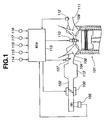
- FIG. 1 there is shown but partially an automotive internal combustion engine 101 to which the present invention is practically applied.
- each combustion chamber of the engine 101 there is introduced air through an air intake duct 102, an intake air collector 103 and an intake manifold 104.
- the air intake duct 102 is equipped with an air flow meter 105 for detecting the flow rate of air and an electronically controlled throttle valve 106 for controlling the amount of air fed to the engine 101.
- Each branch of the intake manifold 104 is equipped with a fuel injection valve 107.
- Each of intake and exhaust valves 108 and 109 of each cylinder of the engine 101 is actuated by an electromagnetic actuator 200 which is well shown in Fig. 2.
- a combustion chamber of each cylinder is equipped with an ignition plug 110 to ignite air-fuel mixture fed thereinto.
- Gas produced in the combustion chamber as a result of combustion of the air-fuel mixture is exhausted into an exhaust manifold 111 through the exhaust valve 109.
- an air/fuel ratio sensor 112 To a united portion of branches of the exhaust manifold 111, there is connected an air/fuel ratio sensor 112 which senses an exhaust air/fuel ratio by measuring an oxygen concentration in the exhaust gas.
- an engine control unit (ECU) 113 which receives information signals from the air flow meter 105 and the air/fuel ratio sensor 112. Into the engine control unit 113, there are also fed information signals from a crank angle sensor 114, an engine cooling water temperature sensor 115, an intake air temperature sensor 116, an accelerator pedal operation degree sensor 117 and a vehicle speed sensor 118.
- the engine control unit (ECU) 113 is a computer which generally comprises a central processing unit (CPU), a random access memory (RAM), a read only memory (ROM), an input interface and an output interface.
- CPU central processing unit
- RAM random access memory
- ROM read only memory
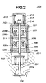
- FIG. 2 there is clearly shown the electromagnetic actuator 200 which actuates each of the intake and exhaust valves 108 and 109.
- the other electromagnetic actuator 200 for the exhaust valve 109 and its surrounding structure are substantially the same as those of the actuator 200 for the intake valve 108.
- a stem 108a of the intake valve 108 is slidably received in a bore (no numeral) formed in a cylinder head 201 of the engine 101.
- the stem 108a has a valve retainer 203 fixed thereto. Between the valve retainer 203 and the cylinder head 201, there is compressed a so-called valve closing spring 204, so that the intake valve 108 is biased upward, that is, in a direction (viz., valve closing direction) to close an intake port 201a of the cylinder head 201.
- the electromagnetic actuator 200 is incorporated with the stem 108a of the intake valve 108 in the following manner.
- the actuator 200 comprises a cylindrical hollow case that includes a circular base member 206 securely mounted on the cylindrical head 201, a cylindrical member 205 mounted on the base member 206 and a circular head member 207 mounted on the cylindrical member 205.
- two, that is, so-called valve opening and closing electromagnets 208 and 209 are immovably disposed, which are coaxially arranged keeping a given distance therebetween. That is, as shown, an upper surface 208b of the valve opening electromagnet 208 and a lower surface 209b of the valve closing electromagnet 209 face each other with the given distance kept therebetween.
- Each electromagnet 208 or 209 is equipped with an energizing coil 208a or 209a. Thus, when the coil 208a or 209a is applied with a certain electric current from a drive circuit (not shown), the corresponding electromagnet 208 or 209 generates a magnetic force.
- a shaft 210 passes slidably through center portions of the two electromagnets 208 and 209.
- the shaft 210 is in alignment with the stem 108a of the intake valve 1087, and a lower end of the shaft 210 is in contact with an upper end 108b of the valve stem 108a.
- the shaft 210 has at its middle portion an armature 211 fixed thereto.
- the armature is made of a magnetic material. As shown, the armature 211 is located in the space between the two electromagnets 208 and 209. Thus, upon energization of the coil 208a or 209a, the shaft 210 is moved downward or upward.
- the shaft 210 has an upper end projected through the head member 207 of the cylindrical hollow case.
- the projected portion of the shaft 210 is equipped with a spring seat 214.
- a spring cover 216 is mounted on the head member 207 to house therein the projected portion of the shaft 210 and the spring seat 214.
- a so-called valve opening spring 215 is compressed between the spring cover 216 and the spring seat 214, so that the shaft 210 is biased downward, that is, in a direction (viz., valve opening direction) to bias the intake valve 108 to open the intake port 201a.
- the shaft 210 is in alignment with the stem 108a of the intake valve 1087, and a lower end of the shaft 210 is in contact with an upper end 108b of the valve stem 108a.
- the shaft 210 pushes down the valve stem 108a and thus moves the intake valve 108 downward to open the intake port 201a
- the valve step 108a is moved upward by the force of the valve closing spring 204 until the intake valve 108 closes the intake port 201a.
- the intake valve 108 is moved to open or close the intake port 201a.
- a position sensor 217 is arranged in the spring cover 216, which detects a position or displacement of the shaft 210.
- a potentiometer may be used as such sensor 217.
- Fig. 3 is a flowchart depicting the entire of the control for the amount of intake air.
- the control is executed for example every 10msec.
- a target pressure in an intake passage (which will be referred to "target intake passage pressure” hereinafter) is set, at step S-502, a target amount of intake air (which will be referred to “target intake air amount” hereinafter) is calculated, and at step S-503, a target open degree of the throttle valve 106 (which will be referred to “target throttle open degree” hereinafter) is calculated based on both the set target intake passage pressure and the calculated target intake air amount.
- a pressure in an intake pipe (which will be referred to "existing intake passage pressure” hereinafter) is detected, and at step S-505, an OPEN/CLOSE timing of the intake valve 108 (which will be referred to "intake valve OPEN/CLOSE timing” hereinafter) is calculated based on both the detected existing intake passage pressure and the calculated target intake air amount.
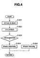
- Fig. 4 is a flowchart depicting the detail of the step S-501 of the flowchart of Fig. 3.
- step S-601 an accelerator pedal operation degree is read, and at step S-602, a vehicle speed is read.
- step S-603 based on both the accelerator pedal operation degree and the vehicle speed, a judgement is carried out as to whether the associated motor vehicle is under a deceleration condition or not, that is, if a driver requires a deceleration (viz., engine brake) of the vehicle or not. If YES, that is, when the accelerator pedal operation degree is smaller than a predetermined degree and the vehicle speed exceeds a predetermined speed, the operation flow goes to step S-604. That is, under the deceleration condition, a negative driving force is needed.
- the target intake passage pressure is set to a relatively low pressure such as - 500mmHg or so.
- step S-605 While, if NO at step S-603, that is, when it is judged that the vehicle is not under the deceleration condition, the operation flow goes to step S-605.
- the target intake passage pressure is set to a relatively high pressure such as -50mmHg or so.
- the deceleration of the vehicle (viz., requirement for engine brake by the driver) is judged based on the accelerator pedal operation degree. If desired, such judgement may be carried out based on both the accelerator pedal operation degree and actual operation of a brake pedal by the driver, or based on only the actual operation of the brake pedal.
- the vehicle is of a type equipped with a vehicle navigation system including GPS (viz., global positioning system)
- a deceleration of the vehicle is forecasted based on a map information given by the navigation system. That is, if the map shows a curve or a down road on the course of the vehicle, the deceleration of the vehicle can be forecasted. In this case, the target intake passage pressure is set to a lower level.
- the navigation system is equipped with a vehicle-information-communication-system (viz., VICS), such forecasting may be effected by using information given by this system.
- the following measure may be used for judging the need of deceleration. That is, in the system, when, during running down on a down road, a vehicle is subjected to a manual shift down operation, such shift down operation is learned and memorized together with a position of the vehicle detected by a navigation system, and when the vehicle comes to the position again during running down on the same down road, a shift down operation is automatically carried out. That is, this automatic shift down operation can be used as an indication of the need of deceleration of the vehicle. Upon receiving such indication, the target intake passage pressure is set to a lower level.
- Fig. 4 shows a flowchart depicting the learning of the position of the vehicle executed when the vehicle is subjected to a manual shift down operation.
- step S-31 a judgement is carried out as to whether or not the existing condition of the vehicle is substantially the same as that assumed when a previous manual shift down operation was carried out. That is, when, with the accelerator pedal operation degree "TVO" being 0 (zero), the vehicle position, the gear position and the vehicle speed changing rate " ⁇ VSP" are the same as those taken at the previous manual shift down operation, it is judged that the existing condition of the vehicle is the same as that assumed at the previous manual shift down operation.
- the reason of adopting the sameness in the vehicle speed changing rate " ⁇ VSP" is as follows. That is, during cruising of a vehicle on a down road, the accelerator pedal operation degree is almost 0 (zero) until the time when a driver effects a manual shifts down operation for achieving an engine brake, and thus, if the vehicle position is the same, the change of the vehicle speed "VSP" from the value shown at the previous shift down operation indicates a predetermined positive value irrespective of variation of the drivers.
- step S-31 that is, when the judgement is so made that the existing condition of the vehicle is not the same as that assumed at the previous manual shift down operation, the operation flow goes to step S-32.
- step S-32 a judgement is carried out as to whether a select lever manipulation currently effected by the driver is intended for a shift down operation or not. If NO, that is, when the select lever manipulation is not intended for the shift down operation, the operation flow goes to END. While, if YES at step S-32, that is, when the select lever manipulation is intended for the shift down operation, the operation flow goes to step S-33. At this step, gear positions assumed before and after the current manual shift down operation are memorized.
- step S-34 a judgement is carried out as to whether the accelerator pedal operation degree "TVO" is 0 (zero) or not. If NO, that is, when the degree "TVO" is not 0 (zero), the operation flow goes to END. While, if YES at step S-34, the operation flow goes to S-35. At this step, a judgement is carried out as to whether the vehicle speed changing rate " ⁇ VSP" is greater than 0 (zero) or not. If NO, that is, when the vehicle speed changing rate " ⁇ VSP" is smaller than 0 (zero), the operation flow goes to END.
- step S-36 a current vehicle position and a travelling direction measured by the vehicle navigation system are read and memorized. Then, the operation flow goes to step S-37. At this step, the current vehicle position, the vehicle speed changing rate " ⁇ VSP" and the above-mentioned gear positions are newly memorized as a learned data on the position where the driver has needed the deceleration (viz., shift down operation) of the vehicle.
- the learned and memorized data at step S-37 is looked up when the vehicle passes through the same position.
- an existing gear position and an existing vehicle speed changing rate " ⁇ VSP" are the same as those of the learned and memorized data, a shift down operation is automatically carried out with the same shift pattern as that taken when the manual shift down operation was carried out.
- the target intake passage pressure is set to a lower level, judging the need of deceleration of the vehicle.
- step S-31 that is, when the existing condition of the vehicle is judged substantially the same as that assumed when the previous manual shift operation was carried out, the operation flow goes to step S-38.
- step S-38 based on the result of learning of the manual shift down operation, a judgement is carried out as to whether or not the vehicle has been subjected to a deceleration before the automatic shift down operation. In fact, this judgement is made by carrying out a judgement whether or not the vehicle has been braked by shifting the select lever in the direction to achieve the shift down operation or depressing the brake pedal. If YES, that is, when the vehicle has been subjected to a deceleration before the automatic shift down operation, the operation flow goes to step S-39.
- step S-39 the learned data is so corrected that the position where the automatic shift down operation is carried out is set much backward, that is, the time when the automatic shift down operation is carried out comes much earlier. While, if NO at step S-38, that is, when the vehicle has not been subjected to a deceleration before the automatic shift down operation, the operation flow goes to step S-40. At this step, a judgement is carried out as to whether or not the vehicle has been subjected to an acceleration after the automatic shift down operation. If NO, that is, when the vehicle has not been subjected to an acceleration after the automatic shift down operation, the operation flow goes to END.
- step S-40 that is, when the vehicle has been subjected to an acceleration after the automatic down shift operation, the operation flow goes to step S-41.
- the learned data is so corrected that the position where the automatic shift down operation is carried out is set much forward, that is, the time when the automatic shift down operation is carried out comes much later.
- Fig. 6 is a flowchart depicting the detail of the step S-502 of the flowchart of Fig. 3.
- the amount of intake air (which will be referred to "idling keeping air amount” hereinafter) needed for keeping an idling condition of the engine is read. That is, the idling keeping air amount is the air amount that is needed when, due to deceleration of the vehicle, the fuel injection is suspended. More specifically, the idling keeping air amount is so set as to produce an engine power that does not produce a marked shock when the fuel injection is restarted.
- step S-703 the accelerator pedal operation degree is read, and at step S-704, a throttle opening degree "Aa” (which will be referred to "driver needed engine power corresponding throttle opening degree”) actually needed by a driver is looked up from a data map which shows a relation between the accelerator pedal operation degree and the throttle opening degree.
- a throttle opening degree "Aa” which will be referred to "driver needed engine power corresponding throttle opening degree” actually needed by a driver is looked up from a data map which shows a relation between the accelerator pedal operation degree and the throttle opening degree.
- a target air volume flowing rate "tQHO" corresponding to the derived "ANV” is looked up from a data map which shows a relation between a target air volume flowing rate (viz., rate of the volume of intake air in a normal condition to a stroke volume) and the target intake air amount.
- the data map used in this step S-707 is provided with reference to an engine having conventional cam actuated intake valves each having a top dead center at its opening time and a bottom dead center at its closing time.
- a lower limit "QHOmin” of the intake air amount (which will be referred to "minimum intake air amount” hereinafter) that allows the amount of lubrication oil sucked into each combustion chamber to be within a permitted range is calculated, and when the target air volume flowing rate "tQHO" derived at step S-707 is smaller than the minimum intake air amount "QHOmin", the minimum intake air amount "QHOmin” is set to the target air volume flowing rate "tQHO".
- the amount of lubrication oil sucked into the combustion chamber will be referred to "amount of sucked lubrication oil” hereinafter.
- the amount of sucked lubrication oil is determined by the pressure in the chamber and the minimum pressure in the combustion chamber at the bottom dead center is determined by the intake air amount.
- the minimum intake air amount "QHOmin” may be set to an amount given when the pressure in the combustion chamber at the bottom dead center shows an allowable minimum value. Since the timing of intake and expansion strokes varies in accordance with the engine speed, the minimum intake air amount "QHOmin” is looked up from a data map based on the engine speed "Ne".
- Fig. 7 is a flowchart depicting the detail of the step S-503 of the flowchart of Fig. 3.
- step S-801 the target air volume flowing rate "tQHO” is read, and at step S-802, the target intake passage pressure "tPman” is read.
- the closing time "IVC” (which will be referred to “intake valve closing time” hereinafter) of the intake valve is fixed to the bottom dead center “BDC" to raise the existing intake passage pressure higher than the target value.
- the gradient of the solid line of Fig. 8 (viz., rate of "ANX” to "QHO" at the time when the existing intake passage pressure is kept constant) is looked up from a previously provided data map based on the target intake passage pressure "tPman". That is, coefficient "C" is derived.
- step S-804 the target air volume flowing rate "tQHO" and the above-mentioned gradient are multiplied together to provide a value " A/(Ne x V) " at the target intake passage pressure, and the value " A/(Ne x V) " is set to "ANVe".
- a value " A/(Ne x V) " in case wherein the intake valve closing time "IVC" is fixed to the bottom dead center “BDC” is derived with reference to a solid curve shown in the graph of Fig. 8, and the value " A/(Ne x V) " is set to "ANVm".
- step S-809 by looking up a data map that shows a relation between the target throttle opening area "At" and the throttle opening degree, the target throttle opening degree is derived.
- the engine control unit (ECU) 113 (see Fig. 1) feeds the electronically controlled throttle valve 106 with an instruction signal based on the target throttle opening degree to cause the valve 106 to take the target throttle opening degree.
- Fig. 9 is a flowchart depicting the detail of the step S-505 of Fig. 3.
- the opening time "EVO" of each exhaust valve is set at the bottom dead center "BDC”
- the closing time “EVC” (which will be referred to “exhaust valve closing time” hereinafter) of the exhaust valve is set at the top dead center “TDC”
- the opening timing "IVO” of each intake valve is set at the top dead center “TDC”
- the intake valve closing time "IVC” is derived from the steps shown in the flowchart of Fig. 9.
- the existing intake passage pressure "Pman” is read.
- a pressure sensor (not shown) is connected to the intake manifold 104 (see Fig. 1).
- estimation technique may be used. That is, by carrying out a real test, a data map is prepared which shows characteristic of a relation between the opening degree of the throttle valve 106 and the pressure in the air intake duct 102, and the characteristic is subjected to an approximation of first-order lag, and a first-order lag treatment is applied to the target intake passage pressure to estimate the existing intake passage pressure actually shown in the air intake duct 102.
- the maximum intake air amount "QHOmax" under the pressure "Pman” is derived. This is carried out by looking up a data map that shows a relation between the maximum intake air amount "QHOmax” and the pressure in the intake duct 102.
- the engine control unit (ECU) 113 feeds each electromagnetic actuator 200 (see Fig. 2) with an instruction signal based on the derived intake valve closing time, so that the intake valve 108 is opened at the top dead center and closed at the derived closing time.
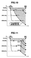
- the throttle opening degree and the intake valve closing time "IVC" under deceleration of the vehicle are calculated for controlling the amount of intake air. Advantages given by such calculation will be described with the aid of Fig. 10 in the following.
- the vehicle is running under a condition wherein the existing intake passage pressure is for example -50mmHg and the intake valve closing time "IVC" is "IVC(1)".
- the target intake passage pressure becomes set to for example -500mmHg to reduce the throttle opening degree.
- the intake valve closing time "IVC” becomes set to a value corresponding to an intake air amount that allows the amount of sucked lubrication oil to be within a predetermined allowable range.
Landscapes
- Engineering & Computer Science (AREA)
- Mechanical Engineering (AREA)
- General Engineering & Computer Science (AREA)
- Chemical & Material Sciences (AREA)
- Combustion & Propulsion (AREA)
- Physics & Mathematics (AREA)
- Electromagnetism (AREA)
- Control Of Throttle Valves Provided In The Intake System Or In The Exhaust System (AREA)
- Electrical Control Of Air Or Fuel Supplied To Internal-Combustion Engine (AREA)
- Output Control And Ontrol Of Special Type Engine (AREA)
Abstract
Description
Claims (9)
- In an engine having an air intake passage, a throttle valve installed in said air intake passage and an intake valve for selectively opening and closing a communication between the intake passage and a cylinder,an intake air control system comprising:a target intake passage pressure setting unit which sets a target pressure in the intake passage of the engine in accordance with an operating condition of the engine;a target intake air amount setting unit which sets a target intake air amount of the engine in accordance with the operating condition of the engine;a target throttle open degree setting unit which sets a target open degree of the throttle valve of the engine in accordance with both said target pressure in the intake passage and said target intake air amount of the engine;a throttle valve drive unit which drives said throttle valve in accordance with said target open degree of the throttle valve;an intake passage pressure detecting unit which detects an existing pressure in said intake passage;a target intake valve OPEN/CLOSE timing setting unit which sets a target OPEN/CLOSE timing of the intake valve in accordance with both the detected existing pressure in said intake passage and said target intake air amount; andan intake valve drive unit which drives said intake valve in accordance with said target OPEN/CLOSE timing of the intake valve.
- An intake air control system as claimed in Claim 1, in which said target intake passage pressure setting unit sets the target pressure in the intake passage at a smaller value when deceleration of an associated motor vehicle is needed.
- An intake air control system as claimed in Claim 1, in which said target intake passage pressure setting unit sets the target pressure in the intake passage at a smaller value when need of deceleration of an associated motor vehicle is forecasted.
- An intake air control system as claimed in Claim 3, in which the forecast of the need of deceleration of the motor vehicle is made based on a road on and along which the vehicle is running.
- An intake air control system as claimed in Claim 1, in which said target intake air amount is set higher than a predetermined lower limit.
- An intake air control system as claimed in Claim 2, in which said target intake air amount setting unit sets a target intake air amount needed when the deceleration of the vehicle takes place.
- An intake air control system as claimed in Claim 4, in which said target intake air amount setting unit sets a target intake air amount needed when the deceleration of the vehicle takes place.
- An intake air control system as claimed in Claim 1, in which said target throttle open degree setting unit sets a target open degree of the throttle valve needed for obtaining said target pressure in the intake passage and sets, as a final target open degree of the throttle valve, the largest open degree needed for obtaining said target intake air amount of the engine when the OPEN/CLOSE timing of said intake valve is set to a predetermined value corresponding to the largest operation angle of the intake valve.
- In an engine having an air intake passage, a throttle valve installed in said air intake passage and an intake valve for selectively opening and closing a communication between the intake passage and a cylinder,method for controlling an amount of intake air, comprising:setting a target pressure in an intake passage of the engine in accordance with an operating condition of the engine;setting a target intake air amount of the engine in accordance with the operating condition of the engine;setting a target open degree of the throttle valve of the engine in accordance with both said target pressure in the intake passage and said target intake air mount of the engine;driving said throttle valve in accordance with said target open degree of the throttle valve;detecting an existing pressure in said intake passage;setting a target OPEN/CLOSE timing of the intake valve in accordance with both the detected existing pressure in said intake passage and said target intake air amount; anddriving said intake valve in accordance with said target OPEN/CLOSE timing of the intake valve.
Applications Claiming Priority (2)
| Application Number | Priority Date | Filing Date | Title |
|---|---|---|---|
| JP00528099A JP3932712B2 (en) | 1999-01-12 | 1999-01-12 | Engine intake control device |
| JP528099 | 1999-01-12 |
Publications (3)
| Publication Number | Publication Date |
|---|---|
| EP1020625A2 true EP1020625A2 (en) | 2000-07-19 |
| EP1020625A3 EP1020625A3 (en) | 2002-12-04 |
| EP1020625B1 EP1020625B1 (en) | 2004-03-24 |
Family
ID=11606839
Family Applications (1)
| Application Number | Title | Priority Date | Filing Date |
|---|---|---|---|
| EP00100452A Expired - Lifetime EP1020625B1 (en) | 1999-01-12 | 2000-01-10 | Intake air control system of internal combustion engine |
Country Status (4)
| Country | Link |
|---|---|
| US (1) | US6263857B1 (en) |
| EP (1) | EP1020625B1 (en) |
| JP (1) | JP3932712B2 (en) |
| DE (1) | DE60009177T2 (en) |
Cited By (11)
| Publication number | Priority date | Publication date | Assignee | Title |
|---|---|---|---|---|
| GB2355493A (en) * | 1999-10-18 | 2001-04-25 | Ford Global Tech Inc | Vehicle engine control method for improved cylinder air charging |
| GB2355498A (en) * | 1999-10-18 | 2001-04-25 | Ford Global Tech Inc | I.c. engine control method |
| US6467442B2 (en) | 1999-10-18 | 2002-10-22 | Ford Global Technologies, Inc. | Direct injection variable valve timing engine control system and method |
| US6490643B2 (en) | 1999-10-18 | 2002-12-03 | Ford Global Technologies, Inc. | Control method for a vehicle having an engine |
| US6560527B1 (en) | 1999-10-18 | 2003-05-06 | Ford Global Technologies, Inc. | Speed control method |
| EP1199456A3 (en) * | 2000-10-16 | 2003-06-04 | Unisia Jecs Corporation | Fail-safe processing system and method for internal combustion engine |
| EP1302645A3 (en) * | 2001-10-12 | 2004-09-29 | Hitachi Unisia Automotive Ltd. | Apparatus and method for controlling the intake air amount of an internal combustion engine |
| EP1329621A3 (en) * | 2002-01-10 | 2006-02-08 | Nissan Motor Co., Ltd. | Intake system for an internal combustion engine |
| US7367316B2 (en) | 1999-10-18 | 2008-05-06 | Ford Global Technologies, Llc | Vehicle control system |
| US7398762B2 (en) | 2001-12-18 | 2008-07-15 | Ford Global Technologies, Llc | Vehicle control system |
| WO2009008527A1 (en) * | 2007-07-10 | 2009-01-15 | Toyota Jidosha Kabushiki Kaisha | Controller and control method for internal combustion engine |
Families Citing this family (7)
| Publication number | Priority date | Publication date | Assignee | Title |
|---|---|---|---|---|
| JP3695118B2 (en) * | 1998-01-12 | 2005-09-14 | トヨタ自動車株式会社 | Control device for electromagnetically driven valve |
| JP2002242708A (en) * | 2001-02-14 | 2002-08-28 | Mikuni Corp | Drive device for direct acting valve for internal combustion engine |
| JP4356892B2 (en) * | 2004-11-30 | 2009-11-04 | 本田技研工業株式会社 | Narrow-angle V-type 2-cylinder 4-stroke engine stroke discrimination device |
| JP4609279B2 (en) * | 2005-11-02 | 2011-01-12 | トヨタ自動車株式会社 | Control device for internal combustion engine |
| US7305300B2 (en) * | 2006-02-13 | 2007-12-04 | Ford Global Technologies, Llc | Closed pedal deceleration control |
| US7464674B2 (en) * | 2006-06-16 | 2008-12-16 | Ford Global Technologies, Llc | Induction air acoustics management for internal combustion engine |
| DE102013113167A1 (en) * | 2013-11-28 | 2015-05-28 | Daimler Ag | Method and device for operating an internal combustion engine |
Family Cites Families (8)
| Publication number | Priority date | Publication date | Assignee | Title |
|---|---|---|---|---|
| JPS6183467A (en) * | 1984-09-29 | 1986-04-28 | Mazda Motor Corp | Control device of engine |
| US4799467A (en) * | 1986-07-16 | 1989-01-24 | Honda Giken Kogyo Kabushiki Kaisha | Throttle valve control system for an internal combustion engine |
| US4791902A (en) * | 1986-07-16 | 1988-12-20 | Honda Giken Kogyo Kabushiki Kaisha | Throttle valve control system for an internal combustion engine |
| JPH02181009A (en) * | 1988-12-28 | 1990-07-13 | Isuzu Motors Ltd | Controller for electromagnetic valve |
| JPH07189795A (en) * | 1993-12-28 | 1995-07-28 | Hitachi Ltd | Vehicle control device and control method |
| JP3134675B2 (en) | 1994-09-12 | 2001-02-13 | 日産自動車株式会社 | Transmission control device for automatic transmission |
| JPH09256823A (en) | 1996-03-25 | 1997-09-30 | Toyota Motor Corp | Electromagnetic drive device for intake and exhaust valves |
| JP3522053B2 (en) | 1996-08-26 | 2004-04-26 | トヨタ自動車株式会社 | Control device for internal combustion engine |
-
1999
- 1999-01-12 JP JP00528099A patent/JP3932712B2/en not_active Expired - Fee Related
-
2000
- 2000-01-10 EP EP00100452A patent/EP1020625B1/en not_active Expired - Lifetime
- 2000-01-10 DE DE60009177T patent/DE60009177T2/en not_active Expired - Lifetime
- 2000-01-12 US US09/481,683 patent/US6263857B1/en not_active Expired - Lifetime
Cited By (33)
| Publication number | Priority date | Publication date | Assignee | Title |
|---|---|---|---|---|
| US7290527B2 (en) | 1999-07-14 | 2007-11-06 | Ford Global Technologies Llc | Vehicle control system |
| US8671909B2 (en) | 1999-07-14 | 2014-03-18 | Ford Global Technologies, Llc | Vehicle control system |
| US8371264B2 (en) | 1999-07-14 | 2013-02-12 | Ford Global Technologies, Llc | Vehicle control system |
| US6945227B2 (en) | 1999-10-18 | 2005-09-20 | Ford Global Technologies, Llc | Direct injection variable valve timing engine control system and method |
| US6467442B2 (en) | 1999-10-18 | 2002-10-22 | Ford Global Technologies, Inc. | Direct injection variable valve timing engine control system and method |
| US6490643B2 (en) | 1999-10-18 | 2002-12-03 | Ford Global Technologies, Inc. | Control method for a vehicle having an engine |
| US6560527B1 (en) | 1999-10-18 | 2003-05-06 | Ford Global Technologies, Inc. | Speed control method |
| GB2355498A (en) * | 1999-10-18 | 2001-04-25 | Ford Global Tech Inc | I.c. engine control method |
| US6626147B2 (en) | 1999-10-18 | 2003-09-30 | Ford Global Technologies, Llc | Control method for a vehicle having an engine |
| US6634328B2 (en) | 1999-10-18 | 2003-10-21 | Ford Global Technologies, Llc | Engine method |
| US6651620B2 (en) | 1999-10-18 | 2003-11-25 | Ford Global Technologies, Llc | Engine method |
| GB2355493B (en) * | 1999-10-18 | 2004-02-18 | Ford Global Tech Inc | Vehicle control method |
| GB2355498B (en) * | 1999-10-18 | 2004-02-18 | Ford Global Tech Inc | Engine control method |
| US6705284B2 (en) | 1999-10-18 | 2004-03-16 | Ford Global Technologies, Llc | Engine method |
| US6712041B1 (en) | 1999-10-18 | 2004-03-30 | Ford Global Technologies, Inc. | Engine method |
| US6250283B1 (en) | 1999-10-18 | 2001-06-26 | Ford Global Technologies, Inc. | Vehicle control method |
| GB2355493A (en) * | 1999-10-18 | 2001-04-25 | Ford Global Tech Inc | Vehicle engine control method for improved cylinder air charging |
| US6470869B1 (en) | 1999-10-18 | 2002-10-29 | Ford Global Technologies, Inc. | Direct injection variable valve timing engine control system and method |
| US6945225B2 (en) | 1999-10-18 | 2005-09-20 | Ford Global Technologies, Llc | Speed control method |
| US7703439B2 (en) | 1999-10-18 | 2010-04-27 | Ford Global Technologies, Llc | Vehicle control system |
| US7000588B2 (en) | 1999-10-18 | 2006-02-21 | Ford Global Technologies, Llc | Engine method |
| US7367316B2 (en) | 1999-10-18 | 2008-05-06 | Ford Global Technologies, Llc | Vehicle control system |
| US7117847B2 (en) | 1999-10-18 | 2006-10-10 | Ford Global Technologies, Llc | Vehicle control system |
| US6962139B2 (en) | 1999-10-18 | 2005-11-08 | Ford Global Technologies, Llc | Speed control method |
| EP1199456A3 (en) * | 2000-10-16 | 2003-06-04 | Unisia Jecs Corporation | Fail-safe processing system and method for internal combustion engine |
| EP1302645A3 (en) * | 2001-10-12 | 2004-09-29 | Hitachi Unisia Automotive Ltd. | Apparatus and method for controlling the intake air amount of an internal combustion engine |
| US7398762B2 (en) | 2001-12-18 | 2008-07-15 | Ford Global Technologies, Llc | Vehicle control system |
| US8251044B2 (en) | 2001-12-18 | 2012-08-28 | Ford Global Technologies, Llc | Vehicle control system |
| US7073469B2 (en) | 2002-01-10 | 2006-07-11 | Nissan Motor Co., Ltd. | Intake system for an internal combustion engine |
| EP1329621A3 (en) * | 2002-01-10 | 2006-02-08 | Nissan Motor Co., Ltd. | Intake system for an internal combustion engine |
| WO2009008527A1 (en) * | 2007-07-10 | 2009-01-15 | Toyota Jidosha Kabushiki Kaisha | Controller and control method for internal combustion engine |
| US8141539B2 (en) | 2007-07-10 | 2012-03-27 | Toyota Jidosha Kabushiki Kaisha | Controller and control method for internal combustion engine |
| CN101965442B (en) * | 2007-07-10 | 2013-02-13 | 丰田自动车株式会社 | Controller and control method for internal combustion engine |
Also Published As
| Publication number | Publication date |
|---|---|
| JP2000204981A (en) | 2000-07-25 |
| DE60009177D1 (en) | 2004-04-29 |
| EP1020625B1 (en) | 2004-03-24 |
| DE60009177T2 (en) | 2004-08-12 |
| EP1020625A3 (en) | 2002-12-04 |
| US6263857B1 (en) | 2001-07-24 |
| JP3932712B2 (en) | 2007-06-20 |
Similar Documents
| Publication | Publication Date | Title |
|---|---|---|
| EP1020625B1 (en) | Intake air control system of internal combustion engine | |
| US6502543B1 (en) | Intake-air quantity control apparatus for internal combustion engines | |
| EP1022442B1 (en) | Intake-air quantity control apparatus for internal combustion engine with variable valve timing system | |
| EP1063393B1 (en) | Intake-air quantity control apparatus for internal combustion engine with variable valve timing system | |
| US6397814B1 (en) | Apparatus and method for controlling intake air quantity for internal combustion engine | |
| EP1106792B1 (en) | Control apparatus for internal combustion engines | |
| EP0867602B1 (en) | Electromagnetically operated valve control system and the method thereof | |
| EP1002939B1 (en) | Intake-air quantity control apparatus for internal combustion engine with variable valve timing system | |
| US5022357A (en) | Control system for internal combustion engine | |
| US6349592B1 (en) | Intake air quantity calculating apparatus for an internal combustion engine with a variable valve timing control mechanism | |
| US6189512B1 (en) | Variable valve timing engine | |
| US4522179A (en) | Engine speed detecting system for multiple-displacement engine | |
| US20040231634A1 (en) | Control system for cylinder cut-off internal combustion engine | |
| US20040163866A1 (en) | Control system for cylinder cut-off internal combustion engine | |
| EP1104842B1 (en) | Intake air control system of engine | |
| US7219004B2 (en) | Adaptive control for engine with electronically adjustable valve operation | |
| EP1104843B1 (en) | System and method for controlling intake air by variable valve timing | |
| EP1104850B1 (en) | System and method of controlling ignition timing in an engine with a variably operated intake valve | |
| JPH0237136A (en) | Throttle opening control device of vehicle mounted internal combustion engine | |
| JP3603612B2 (en) | Engine intake air amount detection device | |
| JPH06117303A (en) | Control device for internal combustion engine |
Legal Events
| Date | Code | Title | Description |
|---|---|---|---|
| PUAI | Public reference made under article 153(3) epc to a published international application that has entered the european phase |
Free format text: ORIGINAL CODE: 0009012 |
|
| 17P | Request for examination filed |
Effective date: 20000110 |
|
| AK | Designated contracting states |
Kind code of ref document: A2 Designated state(s): AT BE CH CY DE DK ES FI FR GB GR IE IT LI LU MC NL PT SE |
|
| AX | Request for extension of the european patent |
Free format text: AL;LT;LV;MK;RO;SI |
|
| PUAL | Search report despatched |
Free format text: ORIGINAL CODE: 0009013 |
|
| AK | Designated contracting states |
Kind code of ref document: A3 Designated state(s): AT BE CH CY DE DK ES FI FR GB GR IE IT LI LU MC NL PT SE |
|
| AX | Request for extension of the european patent |
Free format text: AL;LT;LV;MK;RO;SI |
|
| GRAP | Despatch of communication of intention to grant a patent |
Free format text: ORIGINAL CODE: EPIDOSNIGR1 |
|
| AKX | Designation fees paid |
Designated state(s): DE FR |
|
| GRAS | Grant fee paid |
Free format text: ORIGINAL CODE: EPIDOSNIGR3 |
|
| GRAA | (expected) grant |
Free format text: ORIGINAL CODE: 0009210 |
|
| AK | Designated contracting states |
Kind code of ref document: B1 Designated state(s): DE FR |
|
| REG | Reference to a national code |
Ref country code: IE Ref legal event code: FG4D |
|
| REF | Corresponds to: |
Ref document number: 60009177 Country of ref document: DE Date of ref document: 20040429 Kind code of ref document: P |
|
| ET | Fr: translation filed | ||
| PLBE | No opposition filed within time limit |
Free format text: ORIGINAL CODE: 0009261 |
|
| STAA | Information on the status of an ep patent application or granted ep patent |
Free format text: STATUS: NO OPPOSITION FILED WITHIN TIME LIMIT |
|
| 26N | No opposition filed |
Effective date: 20041228 |
|
| PGFP | Annual fee paid to national office [announced via postgrant information from national office to epo] |
Ref country code: DE Payment date: 20140108 Year of fee payment: 15 |
|
| PGFP | Annual fee paid to national office [announced via postgrant information from national office to epo] |
Ref country code: FR Payment date: 20140108 Year of fee payment: 15 |
|
| REG | Reference to a national code |
Ref country code: DE Ref legal event code: R119 Ref document number: 60009177 Country of ref document: DE |
|
| PG25 | Lapsed in a contracting state [announced via postgrant information from national office to epo] |
Ref country code: DE Free format text: LAPSE BECAUSE OF NON-PAYMENT OF DUE FEES Effective date: 20150801 |
|
| REG | Reference to a national code |
Ref country code: FR Ref legal event code: ST Effective date: 20150930 |
|
| PG25 | Lapsed in a contracting state [announced via postgrant information from national office to epo] |
Ref country code: FR Free format text: LAPSE BECAUSE OF NON-PAYMENT OF DUE FEES Effective date: 20150202 |