EP1020242A2 - Engine crankshaft made by forging - Google Patents
Engine crankshaft made by forging Download PDFInfo
- Publication number
- EP1020242A2 EP1020242A2 EP00100450A EP00100450A EP1020242A2 EP 1020242 A2 EP1020242 A2 EP 1020242A2 EP 00100450 A EP00100450 A EP 00100450A EP 00100450 A EP00100450 A EP 00100450A EP 1020242 A2 EP1020242 A2 EP 1020242A2
- Authority
- EP
- European Patent Office
- Prior art keywords
- crankshaft
- forging
- crank
- inclinations
- counter weight
- Prior art date
- Legal status (The legal status is an assumption and is not a legal conclusion. Google has not performed a legal analysis and makes no representation as to the accuracy of the status listed.)
- Granted
Links
- 238000005242 forging Methods 0.000 title claims abstract description 22
- 230000013011 mating Effects 0.000 claims abstract description 10
- 238000000034 method Methods 0.000 claims abstract description 5
- 238000003825 pressing Methods 0.000 claims description 2
- 238000004519 manufacturing process Methods 0.000 abstract description 8
- 238000003754 machining Methods 0.000 abstract description 4
- 238000002485 combustion reaction Methods 0.000 description 3
- 230000015572 biosynthetic process Effects 0.000 description 1
- 239000000463 material Substances 0.000 description 1
- 239000002994 raw material Substances 0.000 description 1
Images

Classifications
-
- B—PERFORMING OPERATIONS; TRANSPORTING
- B21—MECHANICAL METAL-WORKING WITHOUT ESSENTIALLY REMOVING MATERIAL; PUNCHING METAL
- B21K—MAKING FORGED OR PRESSED METAL PRODUCTS, e.g. HORSE-SHOES, RIVETS, BOLTS OR WHEELS
- B21K1/00—Making machine elements
- B21K1/06—Making machine elements axles or shafts
- B21K1/08—Making machine elements axles or shafts crankshafts
-
- F—MECHANICAL ENGINEERING; LIGHTING; HEATING; WEAPONS; BLASTING
- F16—ENGINEERING ELEMENTS AND UNITS; GENERAL MEASURES FOR PRODUCING AND MAINTAINING EFFECTIVE FUNCTIONING OF MACHINES OR INSTALLATIONS; THERMAL INSULATION IN GENERAL
- F16C—SHAFTS; FLEXIBLE SHAFTS; ELEMENTS OR CRANKSHAFT MECHANISMS; ROTARY BODIES OTHER THAN GEARING ELEMENTS; BEARINGS
- F16C3/00—Shafts; Axles; Cranks; Eccentrics
- F16C3/04—Crankshafts, eccentric-shafts; Cranks, eccentrics
- F16C3/06—Crankshafts
- F16C3/08—Crankshafts made in one piece
-
- F—MECHANICAL ENGINEERING; LIGHTING; HEATING; WEAPONS; BLASTING
- F16—ENGINEERING ELEMENTS AND UNITS; GENERAL MEASURES FOR PRODUCING AND MAINTAINING EFFECTIVE FUNCTIONING OF MACHINES OR INSTALLATIONS; THERMAL INSULATION IN GENERAL
- F16C—SHAFTS; FLEXIBLE SHAFTS; ELEMENTS OR CRANKSHAFT MECHANISMS; ROTARY BODIES OTHER THAN GEARING ELEMENTS; BEARINGS
- F16C3/00—Shafts; Axles; Cranks; Eccentrics
- F16C3/04—Crankshafts, eccentric-shafts; Cranks, eccentrics
- F16C3/20—Shape of crankshafts or eccentric-shafts having regard to balancing
-
- F—MECHANICAL ENGINEERING; LIGHTING; HEATING; WEAPONS; BLASTING
- F16—ENGINEERING ELEMENTS AND UNITS; GENERAL MEASURES FOR PRODUCING AND MAINTAINING EFFECTIVE FUNCTIONING OF MACHINES OR INSTALLATIONS; THERMAL INSULATION IN GENERAL
- F16C—SHAFTS; FLEXIBLE SHAFTS; ELEMENTS OR CRANKSHAFT MECHANISMS; ROTARY BODIES OTHER THAN GEARING ELEMENTS; BEARINGS
- F16C2360/00—Engines or pumps
- F16C2360/22—Internal combustion engines
-
- Y—GENERAL TAGGING OF NEW TECHNOLOGICAL DEVELOPMENTS; GENERAL TAGGING OF CROSS-SECTIONAL TECHNOLOGIES SPANNING OVER SEVERAL SECTIONS OF THE IPC; TECHNICAL SUBJECTS COVERED BY FORMER USPC CROSS-REFERENCE ART COLLECTIONS [XRACs] AND DIGESTS
- Y10—TECHNICAL SUBJECTS COVERED BY FORMER USPC
- Y10T—TECHNICAL SUBJECTS COVERED BY FORMER US CLASSIFICATION
- Y10T74/00—Machine element or mechanism
- Y10T74/21—Elements
- Y10T74/2173—Cranks and wrist pins
- Y10T74/2183—Counterbalanced
Definitions
- the present invention generally relates to a forged crankshaft for an internal combustion engine, and more particularly to such a crankshaft having larger counter weights but not causing interference between the counter weights and neighboring parts of the engine.
- crankshafts for internal combustion engines by forging are known in the art.
- a crankshaft has a plurality of counter weights to improve dynamic balance of the crankshaft.
- the improved dynamic balance will reduce vibrations of the engine.
- larger counter weights may be attached to the crankshaft so that a weight of the crankshaft with the counter weights increases.
- other parts such as pistons, connecting rods and cylinder block exist near the counter weights, so that use of larger counter weights is generally difficult.
- the counter weights may be machined to complicated shapes so that the counter weights extend in gaps between the neighboring parts and do not contact the neighboring parts. This approach, however, raises a manufacturing cost of the crankshaft because of the machining process.
- An object of the present invention is to provide a crankshaft for an internal combustion engine, on which larger counter weights can be mounted without increasing the manufacturing process step and cost.
- Another object of the present invention is to provide an engine crankshaft having larger counter weights that do not interfere with neighboring parts.
- Still another object of the present invention is to provide a forged crankshaft having larger counter weights that can be fabricated by simply changing forging dies while employing a conventional manufacturing method in other aspects.
- Yet another object of the present invention is to provide a method of manufacturing an engine crankshaft by forging, which can realize both easy removal of forging dies from a product (crankshaft) and formation of large counter weights.
- an engine crankshaft having at least one counter weight and made by forging, the forging being performed by pressing two dies with each other, characterized in that the counter weight has a plurality of inclinations to facilitate removal of the dies from the crankshaft after the forging process is completed, and degree of inclination of the plurality of inclinations is reduced as the plurality of inclinations are apart from a die mating surface.
- each counter weight has a single inclination to facilitate removal of the forging dies from the crankshaft.
- a plurality of inclinations to effectively enlarge the size of each counter weight. The inclinations are determined such that the maximum thickness of each counter weight is not enlarged, but the total volume of the counter weights is enlarged. Since the maximum thickness is the same as a conventional crankshaft, interference between the crankshaft and neighboring parts is avoided. No machining is required after the fording process, in order to have counter weights having a desired enlarged shape.
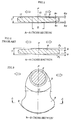
- crankshaft 1 illustrated is a crankshaft 1 according to the present invention that is made by forging.
- This crankshaft 1 may be used with a four-cylinder engine.
- the crankshaft 1 has five crank journals 5 coaxially.
- a centerline C of the crankshaft 1 is defined by these five crank journals 5.
- the crank journals 5 are rotatably supported by bearing portions of a cylinder block (not shown). Between each two adjacent crank journals 5, formed is a crank portion 4.
- This crankshaft 1 has, therefore, four crank portions 4 for four cylinders.
- Each crank portion 4 has a crank pin 2 that engages with a large end of an associated connecting rod (not shown), and a pair of crank arms 3 bridging the crank pin 2 and associated crank journals 5.
- Two of the four crank portions 4 at the ends of the crankshaft 1 have a 180-degree phase difference relative to other two crank portions 4 at the center.
- An auxiliary drive shaft 6 extends coaxially from the left end crank journal 5, and an output flange shaft 7 extends coaxially from the right end crank journal 5.
- Each crank arm 3 has a counter weight 8 in such a manner that the counter weight 8 is positioned opposite the associated crank pin 2 with respect to the crankshaft centerline C.
- each counter weight 8 has a larger width than the crank arm 3 when viewed in the axial direction of the crankshaft.
- the counter weight 8 has an arc periphery about the center C.
- the phantom line 9 in the drawing indicates a neighboring part. Only a slight clearance is left between the counter weight 8 and the neighboring part 9.
- crankshaft 1 When the crankshaft 1 is forged, utilized are a pair of metallic molds (not shown) that are divisible in a direction perpendicular to the sheet of Figure 4. Each metallic mold forms a half of the crankshaft 1.
- the line P in Figure 3 which extends vertically through the crankshaft center C and the center of the crank pin 2, indicates the mating face of the two metallic molds.
- Two opposite unshaded arrows in Figure 3 indicate the directions in which the metallic molds are separated.
- each counter weight 8' has inclination ⁇ to facilitate removal of an associated die (not shown) from the counter weight 8 .
- each of the counter weights 8' is reduced in thickness as it is apart from the die mating surface P, so that each counter weight 8' has a predetermined constant taper on both sides.
- T indicates a counter weight maximum thickness which is acceptable in view of neighboring parts (not shown) when the crankshaft is assembled in an engine.
- FIG. 1 illustrated is a similar cross sectional view of the crankshaft 1 according to the present invention.
- the taper of the counter weight 8 is relatively large in an area close to the die mating surface P and relatively small in a further area.
- the counter weight 8 has a first inclination ⁇ 1 in the center area 10 (indicated by the double arrow D) and a second smaller inclination ⁇ 2 ( ⁇ 2 ⁇ 1) in a distal area 11.
- ⁇ 1 2 degrees
- ⁇ 2 1 degree.
- the counter weight 8 has two different tapers.
- Other aspects of the crankshaft 1 of the invention are the same as the conventional crankshaft shown in Figure 2.
- the same or similar reference symbols are used in Figures 1 and 2 to designate same or similar elements.
- the maximum thickness T is the same in Figures 1 and 2.
- the thickness of the counter weight 8 shown in Figure 1 in the distal area 11 is greater than the conventional counter weight 8' shown in Figure 2. Therefore, it is possible to employ larger (and heavier) counter weights as compared with the conventional crankshaft. It should be noted that this weight increase is realized without enlarging the maximum thickness T of the counter weight. Therefore, interference with the neighboring parts would not arise.
- the present invention can provide large-scaled counter weights 8 without causing drawbacks. With this idea, no manufacturing disadvantages arise, but performance of the engine equipped with the crankshaft 1 of the invention is simply improved.
- the present invention is not limited to the illustrated and described crankshaft 1.
- the first and second inclinations may have values other than 2° and 1°.
- the counter weight 8 may have three or more different inclinations. In this case, the inclinations are reduced in turn as they are apart from the die mating surface P.
- the present invention is also applicable to an engine having cylinders more or less than four.
Landscapes
- Engineering & Computer Science (AREA)
- General Engineering & Computer Science (AREA)
- Mechanical Engineering (AREA)
- Ocean & Marine Engineering (AREA)
- Shafts, Cranks, Connecting Bars, And Related Bearings (AREA)
- Forging (AREA)
Abstract
Description
- Figure 1
- illustrates a cross sectional view of a counter weight according to the present invention, taken along the line A-A in Figure 3;
- Figure 2
- is similar to Figure 1, illustrating a cross sectional view of a counter weight according a prior art, which should be compared with Figure 1;
- Figure 3
- illustrates a transversal cross sectional view of the crankshaft according to the present invention, taken along the line B-B in Figure 4; and
- Figure 4
- illustrates a front view of the crankshaft according to the present invention.

Claims (6)
- An engine crankshaft (1) having at least one counter weight (8) and made by forging, the forging being performed by pressing two dies with each other, characterized in that the counter weight (8) has a plurality of inclinations (1, 2) to facilitate removal of the dies from the crankshaft after the forging process is completed, and degree of inclination of the plurality of inclinations is reduced as the plurality of inclinations are apart from a die mating surface (P).
- The engine crankshaft (1) according to claim 1, characterized in that the crankshaft includes a plurality of coaxial crank journals (5), and at least one crank portion (4) having a crank pin (2), a pair of crank arms (3), and a pair of counter weights (8) extending from the pair of crank arms in an opposite direction apart from the crank pin.
- The engine crankshaft (1) according to claim 1 or 2, characterized in that the engine crankshaft has four crank portions (4).
- The engine crankshaft (1) according to claim 1, 2 or 3, characterized in that each counter weight (8) has a greater width than the crank arm (3) when viewed in an axial direction of the crankshaft.
- The engine crankshaft (1) according to claim 1, 2, 3 or 4, characterized in that the plurality of inclinations are first and second inclinations ( 1, 2).
- The engine crankshaft (1) according to claim 6, characterized in that the first inclination (1) is 2 degrees and the second inclination (2) is 1 degree.
Applications Claiming Priority (2)
| Application Number | Priority Date | Filing Date | Title |
|---|---|---|---|
| JP676699 | 1999-01-13 | ||
| JP11006766A JP2000205238A (en) | 1999-01-13 | 1999-01-13 | Forged crankshaft |
Publications (3)
| Publication Number | Publication Date |
|---|---|
| EP1020242A2 true EP1020242A2 (en) | 2000-07-19 |
| EP1020242A3 EP1020242A3 (en) | 2001-07-18 |
| EP1020242B1 EP1020242B1 (en) | 2004-03-24 |
Family
ID=11647311
Family Applications (1)
| Application Number | Title | Priority Date | Filing Date |
|---|---|---|---|
| EP00100450A Expired - Lifetime EP1020242B1 (en) | 1999-01-13 | 2000-01-10 | Engine crankshaft made by forging |
Country Status (4)
| Country | Link |
|---|---|
| US (1) | US6324942B1 (en) |
| EP (1) | EP1020242B1 (en) |
| JP (1) | JP2000205238A (en) |
| DE (1) | DE60009175T2 (en) |
Cited By (2)
| Publication number | Priority date | Publication date | Assignee | Title |
|---|---|---|---|---|
| FR2892475A1 (en) * | 2005-10-26 | 2007-04-27 | Renault Sas | CRANKSHAFT OF AN INTERNAL COMBUSTION ENGINE COMPRISING AN INERTIAL MASS AND MOTOR COMPRISING SUCH A CRANKSHAFT |
| WO2017089977A1 (en) | 2015-11-24 | 2017-06-01 | Bharat Forge Limited | A forged crankshaft and a process of making it |
Families Citing this family (10)
| Publication number | Priority date | Publication date | Assignee | Title |
|---|---|---|---|---|
| DE102004013870A1 (en) * | 2004-03-20 | 2005-10-06 | Andreas Stihl Ag & Co. Kg | crankshaft |
| JP2007071227A (en) * | 2005-09-02 | 2007-03-22 | Toyota Motor Corp | Inline 4-cylinder engine crankshaft |
| JP2009002395A (en) * | 2007-06-20 | 2009-01-08 | Nissan Motor Co Ltd | Crankshaft |
| US20090229545A1 (en) * | 2008-03-13 | 2009-09-17 | Compressco, Inc. | Crankshaft for integral gas compressor and internal combustion engine |
| US8100104B2 (en) * | 2008-06-05 | 2012-01-24 | Ford Global Technologies | Torsion lock encoder device for internal combustion engine |
| KR100957164B1 (en) * | 2008-08-25 | 2010-05-11 | 현대자동차주식회사 | Balance weight system of crankshaft |
| JP5397957B2 (en) * | 2010-10-22 | 2014-01-22 | 株式会社メタルアート | Crankshaft manufacturing method and crankshaft manufactured by the manufacturing method |
| US8967112B2 (en) * | 2012-11-16 | 2015-03-03 | GM Global Technology Operations LLC | Four counterweight crankshaft for 90 degree V6 engine |
| DE102013206931A1 (en) * | 2013-04-17 | 2014-10-23 | Ford Global Technologies, Llc | Internal combustion engine comprising a crankshaft with balancing weight serving as unbalance and method for producing the crankshaft |
| CN113915272B (en) * | 2021-09-22 | 2023-03-21 | 华北水利水电大学 | A magnetic liquid damping shock absorber |
Family Cites Families (12)
| Publication number | Priority date | Publication date | Assignee | Title |
|---|---|---|---|---|
| US1661341A (en) * | 1928-03-06 | of wobcester | ||
| US1705165A (en) * | 1920-04-06 | 1929-03-12 | Twyman B Wickliffe | Counterweight for shafts and method for attaching |
| US1705187A (en) * | 1920-05-27 | 1929-03-12 | Wickliffe Twyman B | Counterweight means for crank shafts and process of forming and attaching |
| US1660171A (en) * | 1921-02-28 | 1928-02-21 | Wyman Gordon Co | Counterweighted crank shaft and method of making same |
| US1756659A (en) * | 1928-07-19 | 1930-04-29 | Wyman Gordon Co | Counterbalanced crank shaft |
| US2815682A (en) | 1954-09-29 | 1957-12-10 | Gen Motors Corp | Crankshaft |
| US4730512A (en) * | 1984-10-23 | 1988-03-15 | Toyota Jidosha Kabushiki Kaisha | Engine crankshaft structure |
| DE3608810A1 (en) * | 1986-03-15 | 1987-09-24 | Porsche Ag | CRANKSHAFT FOR LIFTING PISTON MACHINES |
| US5305656A (en) * | 1990-12-21 | 1994-04-26 | Toyota Jidosha Kabushiki Kaisha | Balancer apparatus for engine |
| JPH0679406A (en) | 1992-09-04 | 1994-03-22 | Honda Motor Co Ltd | Crankshaft material for internal combustion engine and molding die |
| JPH08105431A (en) | 1994-09-30 | 1996-04-23 | Suzuki Motor Corp | Crankshaft |
| JPH1029032A (en) | 1996-07-17 | 1998-02-03 | Sumitomo Metal Ind Ltd | Mold for crankshaft forging and method for manufacturing crankshaft |
-
1999
- 1999-01-13 JP JP11006766A patent/JP2000205238A/en active Pending
-
2000
- 2000-01-04 US US09/478,242 patent/US6324942B1/en not_active Expired - Fee Related
- 2000-01-10 EP EP00100450A patent/EP1020242B1/en not_active Expired - Lifetime
- 2000-01-10 DE DE60009175T patent/DE60009175T2/en not_active Expired - Lifetime
Cited By (2)
| Publication number | Priority date | Publication date | Assignee | Title |
|---|---|---|---|---|
| FR2892475A1 (en) * | 2005-10-26 | 2007-04-27 | Renault Sas | CRANKSHAFT OF AN INTERNAL COMBUSTION ENGINE COMPRISING AN INERTIAL MASS AND MOTOR COMPRISING SUCH A CRANKSHAFT |
| WO2017089977A1 (en) | 2015-11-24 | 2017-06-01 | Bharat Forge Limited | A forged crankshaft and a process of making it |
Also Published As
| Publication number | Publication date |
|---|---|
| DE60009175D1 (en) | 2004-04-29 |
| EP1020242A3 (en) | 2001-07-18 |
| EP1020242B1 (en) | 2004-03-24 |
| US6324942B1 (en) | 2001-12-04 |
| JP2000205238A (en) | 2000-07-25 |
| DE60009175T2 (en) | 2004-09-30 |
Similar Documents
| Publication | Publication Date | Title |
|---|---|---|
| EP1020242B1 (en) | Engine crankshaft made by forging | |
| US7810411B2 (en) | Connecting rod assembly for an internal combustion engine | |
| EP1812202B1 (en) | Method of manufacturing a connecting rod assembly for an internal combustion engine | |
| EP3072609B1 (en) | Method for producing a forged crank shaft | |
| US8613137B2 (en) | Connecting rod lubrication recess | |
| US4881427A (en) | Crankshaft of internal combustion engine and method of producing the same | |
| WO2016159246A1 (en) | Method for manufacturing forged crankshaft | |
| JP2009208147A (en) | Method for manufacturing crankshaft and forming die used therefor | |
| CN109322903B (en) | Balance weight and crankshaft comprising same | |
| US11300073B2 (en) | Cylinder block assembly | |
| JP2998058B2 (en) | V-type 6-cylinder engine crankshaft and method of manufacturing the same | |
| WO2006057593A1 (en) | Crankshaft and method for manufacturing such a crankshaft | |
| JPS63180336A (en) | Crankshaft manufacturing method | |
| JPH0526224A (en) | Manufacture of cylinder block of engine | |
| JPS58132342A (en) | Forging method of coarse material of crank shaft | |
| US20180172064A1 (en) | Method for manufacturing crankshaft, and crankshaft | |
| JPWO2018230500A1 (en) | Manufacturing method of forged crankshaft | |
| JP2003112225A (en) | Rocker arm | |
| WO2018100810A1 (en) | Production method for forged crankshaft | |
| JP3390171B2 (en) | Crankshaft for two-stroke engine and use thereof | |
| JPH02180308A (en) | Cast crank shaft for internal combustion engine | |
| JP4108268B2 (en) | CRANKSHAFT, MANUFACTURING METHOD THEREOF, AND ENGINE WITH CRANKSHAFT | |
| EP3309417B1 (en) | Crankshaft for reciprocating engine | |
| JP7485951B2 (en) | Manufacturing method of crankshaft | |
| JP6380670B2 (en) | Forging crankshaft manufacturing equipment |
Legal Events
| Date | Code | Title | Description |
|---|---|---|---|
| PUAI | Public reference made under article 153(3) epc to a published international application that has entered the european phase |
Free format text: ORIGINAL CODE: 0009012 |
|
| AK | Designated contracting states |
Kind code of ref document: A2 Designated state(s): DE FR GB |
|
| AX | Request for extension of the european patent |
Free format text: AL;LT;LV;MK;RO;SI |
|
| PUAL | Search report despatched |
Free format text: ORIGINAL CODE: 0009013 |
|
| AK | Designated contracting states |
Kind code of ref document: A3 Designated state(s): AT BE CH CY DE DK ES FI FR GB GR IE IT LI LU MC NL PT SE |
|
| AX | Request for extension of the european patent |
Free format text: AL;LT;LV;MK;RO;SI |
|
| RIC1 | Information provided on ipc code assigned before grant |
Free format text: 7B 21K 1/08 A, 7F 16C 3/08 B, 7F 16C 3/20 B |
|
| 17P | Request for examination filed |
Effective date: 20010829 |
|
| AKX | Designation fees paid |
Free format text: DE FR GB |
|
| GRAH | Despatch of communication of intention to grant a patent |
Free format text: ORIGINAL CODE: EPIDOS IGRA |
|
| GRAS | Grant fee paid |
Free format text: ORIGINAL CODE: EPIDOSNIGR3 |
|
| GRAA | (expected) grant |
Free format text: ORIGINAL CODE: 0009210 |
|
| AK | Designated contracting states |
Kind code of ref document: B1 Designated state(s): DE FR GB |
|
| PG25 | Lapsed in a contracting state [announced via postgrant information from national office to epo] |
Ref country code: FR Free format text: LAPSE BECAUSE OF FAILURE TO SUBMIT A TRANSLATION OF THE DESCRIPTION OR TO PAY THE FEE WITHIN THE PRESCRIBED TIME-LIMIT Effective date: 20040324 |
|
| REG | Reference to a national code |
Ref country code: GB Ref legal event code: FG4D |
|
| REF | Corresponds to: |
Ref document number: 60009175 Country of ref document: DE Date of ref document: 20040429 Kind code of ref document: P |
|
| PG25 | Lapsed in a contracting state [announced via postgrant information from national office to epo] |
Ref country code: GB Free format text: LAPSE BECAUSE OF NON-PAYMENT OF DUE FEES Effective date: 20050110 |
|
| PLBE | No opposition filed within time limit |
Free format text: ORIGINAL CODE: 0009261 |
|
| STAA | Information on the status of an ep patent application or granted ep patent |
Free format text: STATUS: NO OPPOSITION FILED WITHIN TIME LIMIT |
|
| EN | Fr: translation not filed | ||
| 26N | No opposition filed |
Effective date: 20041228 |
|
| GBPC | Gb: european patent ceased through non-payment of renewal fee |
Effective date: 20050110 |
|
| PGFP | Annual fee paid to national office [announced via postgrant information from national office to epo] |
Ref country code: DE Payment date: 20110105 Year of fee payment: 12 |
|
| PG25 | Lapsed in a contracting state [announced via postgrant information from national office to epo] |
Ref country code: DE Free format text: LAPSE BECAUSE OF NON-PAYMENT OF DUE FEES Effective date: 20120801 |
|
| REG | Reference to a national code |
Ref country code: DE Ref legal event code: R119 Ref document number: 60009175 Country of ref document: DE Effective date: 20120801 |