EP1020102B1 - Electronics cabinet and air channel system for an electronics cabinet - Google Patents
Electronics cabinet and air channel system for an electronics cabinet Download PDFInfo
- Publication number
- EP1020102B1 EP1020102B1 EP98946469A EP98946469A EP1020102B1 EP 1020102 B1 EP1020102 B1 EP 1020102B1 EP 98946469 A EP98946469 A EP 98946469A EP 98946469 A EP98946469 A EP 98946469A EP 1020102 B1 EP1020102 B1 EP 1020102B1
- Authority
- EP
- European Patent Office
- Prior art keywords
- space
- cabinet
- sub
- opening
- air
- Prior art date
- Legal status (The legal status is an assumption and is not a legal conclusion. Google has not performed a legal analysis and makes no representation as to the accuracy of the status listed.)
- Expired - Lifetime
Links
Images


Classifications
-
- H—ELECTRICITY
- H05—ELECTRIC TECHNIQUES NOT OTHERWISE PROVIDED FOR
- H05K—PRINTED CIRCUITS; CASINGS OR CONSTRUCTIONAL DETAILS OF ELECTRIC APPARATUS; MANUFACTURE OF ASSEMBLAGES OF ELECTRICAL COMPONENTS
- H05K7/00—Constructional details common to different types of electric apparatus
- H05K7/20—Modifications to facilitate cooling, ventilating, or heating
- H05K7/20536—Modifications to facilitate cooling, ventilating, or heating for racks or cabinets of standardised dimensions, e.g. electronic racks for aircraft or telecommunication equipment
- H05K7/206—Air circulating in closed loop within cabinets wherein heat is removed through air-to-air heat-exchanger
Definitions
- the present invention relates to an electronics cabinet as defined in the preamble of claim 1.
- an electronics cabinet which comprises an enclosure with an interior space where electronic parts, such as circuit cards and the like, can be mounted.
- the cabinet is also provided with a cooling system for cooling the space inside the cabinet.
- the cooling system is an integral assembly attached to the enclosure in the immediate vicinity of its interior space.
- the cooling system comprises means for internal air circulation within the interior space, for conveying an external air circulation separated from the internal air circulation into and out of the cooling system and for cooling the internal circulation air by means of the external air circulation.
- the means for conveying the air consist of a complex sheet metal structure comprising several bent sheet metal parts, in which the air flow channels are formed from a large number of bent sheet metal parts joined together. To damp the noise generated by the air flow, the sheet metal structure is additionally lined with foamed plastic panels.
- the object of the present invention is to eliminate the drawbacks mentioned above.
- a specific object of the invention is to present an electronics cabinet and an air channel system for the cabinet that are simple in structure as well as cheap and allow easy assembly of the unit.
- the electronics cabinet of the invention is characterised by what is presented in claim 1.
- the electronics cabinet of the invention comprises an enclosure with an interior space where electronic parts, such as circuit cards and the like, can be mounted, and a cooling system implemented as a substantially integral assembly with the enclosure and disposed in the immediate vicinity of the interior space for cooling said space.
- the cooling system comprises means for internal air circulation within the interior space, for conveying an external air circulation separated from the internal air circulation into and out of the cooling system and for cooling the air in the internal circulation by means of the external air circulation.
- the means for conveying the external air circulation comprise a body made from foamed material with a flow channel formed in it, through which at least part of the external air circulation is passed.
- the invention provides the advantage that the air channel system is simpler and considerably cheaper than earlier systems. Assembling the electronics cabinet becomes easier because the number of parts and holding fixtures is smaller than before. Moreover, the noise generated by fans and air flow can be effectively damped because the vibrations are effectively damped by the foamed plastic material.
- the body made of foamed material is a body of foamed plastic.
- the cooling system comprises an exterior wall, a first partition wall placed at a distance from the exterior wall and substantially parallel with it; side walls which, together with the exterior wall and the first partition wall, form a hollow first interspace, into which the body has been fitted; a first opening in the exterior wall, a second opening in the first partition wall; and an inlet flow channel in the body, serving to convey external air from the first opening into the second opening.
- the cooling system comprises a second partition wall, which is located at a distance from the first partition wall and is substantially parallel with it and, together with the first partition wall and the side walls, delimits a hollow second interspace and separates the cooling system from the interior cabinet space containing electronic parts to be cooled.
- the second partition wall is provided with a third opening.
- an air-to-air heat exchanger is provided in the second interspace. The heat exchanger divides the second interspace into four sub-spaces.
- the first and the second sub-spaces are for external air circulation and are located on opposite sides of the heat exchanger.
- the third and the fourth sub-spaces are for internal air circulation and are correspondingly located on opposite sides of the heat exchanger.
- An external-air fan for creating an external air circulation is placed in a cut-out, opening or the like formed in the body in the area of the second sub-space and constituting an exit channel for conveying the external air flow out of the cabinet.
- the external-air fan On the suction side, the external-air fan has been arranged to produce suction to draw the external air flow through the first opening, the inlet flow channel and the second opening into the first sub-space and further through the heat exchanger into the second sub-space. From the second sub-space, the air flow is passed further via the third opening in the first partition wall through the external-air fan, from where it is blown out of the cabinet through the outlet channel in the body.
- the second partition wall comprises a fourth opening, which is located in the area of the third sub-space for passing internal air from the interior space into the third sub-space, and a fifth opening, which is located in the area of the fourth sub-space.
- the cooling system comprises a internal-air fan, which is disposed in the area of the fifth opening.
- the internal-air fan has been arranged to circulate the internal air from the interior space of the cabinet through the fourth opening into the third sub-space and further through the heat exchanger into the fourth sub-space and further via the fifth opening to the pressure side of the internal-air fan and back into the interior space.
- the cooling system comprises air blow channels arranged to convey the cooled internal air blow from the internal-air fan into the interior space, between the electronic parts, such as electronic circuit cards.
- the size of the body has been fitted to equal the size of the first interspace so as to fill substantially the entire first interspace.
- the size of the body has been fitted to be smaller than the first interspace so as to leave some space for passing an air flow between the body and the walls delimiting the first interspace.
- the electronics cabinet is a cabinet designed for use in outdoor locations, e.g. as an enclosure for a base transceiver station comprised in a wireless telecommunication system.
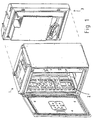
- Fig. 1 shows an electronics cabinet, which in this example is an enclosure for a base transceiver station comprised in a wireless telecommunication system, designed for use in outdoor locations. Such an outdoor base station cabinet is exposed to weather, so it has to be of a tight structure.
- the electronics housed in the cabinet develops a fairly high temperature, e.g. as high as 90°C, in the interior space of the cabinet, which is cooled by means of an air cooling system 3.
- the figure shows an enclosure 1 with an interior space 2 where electronic parts, such as circuit cards and the like, can be mounted, and a cooling system 3, which can be installed as a compact unit in conjunction with the enclosure 1 so that it simultaneously forms a back wall.
- the cooling system 3 comprises means for circulating air as a closed internal air circulation within the interior space. Moreover, the cooling system 3 comprises means for passing an open external air circulation separated from the internal air circulation into and out of the cooling system. The air circulated within the interior space is cooled by the external air circulation. The exchange of heat between the internal and the external air circulation systems is effected using an air-to-air heat exchanger 17 as shown in Fig. 2.
- the external air circulation has been described above by referring to Fig. 4 - 6, and the internal air circulation has been described by referring to Fig. 7 and 8.
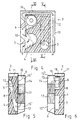
- Fig. 3 presents a foamed plastic body 4 formed from a single solid piece of foamed plastic material, containing flow channels 5, 6, 7, through which some of the external air circulation is conveyed.
- the foamed plastic body 4 is mounted inside the cooling system enclosure 3 as described below.
- the foamed plastic body 4 can be produced from plastic foam e.g. by the injection moulding method using one or two moulds.
- the cooling system part 3 comprises an exterior wall 8, a first partition wall 9, which is placed at a distance from the exterior wall and substantially parallel with it, and side walls 10, which, together with the exterior wall 8 and the first partition wall 9, form a hollow first interspace 11.
- the foamed plastic body 4 presented in Fig. 3 is mounted in this interspace 11.
- the size of the foamed plastic body 4 has been fitted to be smaller than the first interspace 11 so as to leave a space for passing the external air flow between the foamed plastic body 4 and the walls delimiting the first interspace 11.
- the exterior wall 8 has a first opening 12.
- the first partition wall 9 has a second opening 13.
- the foamed plastic body 4 contains an external air inlet channel 5 for conveying external air from the first opening 12 into the second opening 13.
- the second partition wall 14 is located at a distance from the first partition wall 9 and is substantially parallel with it. Together with the first partition wall 9 and the side walls, the second partition wall 14 delimits a hollow second interspace 15. In addition, the second partition wall 14 separates the cooling system 3 from the interior cabinet space 2, which contains electronic parts to be cooled.
- the second partition wall 14 has a third opening 16.
- An air-to-air heat exchanger 17 has been fitted in the second interspace 15.
- the heat exchanger 17 divides the second interspace into four sub-spaces 15 1 , 15 2 , 15 3 , 15 4 .
- the first sub-space 15 1 and the second sub-space 15 2 are for external air circulation and are located on opposite sides of the heat exchanger 17.
- the first sub-space 15 1 and the second sub-space 15 2 communicate with each other through the heat exchanger 17.
- the third sub-space 15 3 and the fourth sub-space 15 4 are for internal air circulation and are correspondingly located on opposite sides of the heat exchanger 17.
- the third sub-space 15 3 and the fourth sub-space 15 4 communicate with each other through the heat exchanger 17.
- An external-air fan 18 creates an external air circulation.
- the external-air fan 18 is placed in a cut-out 6 formed in the foamed plastic body 4 in the area of the second sub-space 15 2 .
- the cut-out constitutes an exit channel for conveying the external air flow out of the cabinet.
- the external air flow passes through the cooling system 3 as follows.
- the external-air fan 18 sucks air from outside through the first opening 12, the inlet flow channel 5 and the second opening 13 into the first sub-space 15 1 and further through the heat exchanger 17 into the second sub-space 15 2 , and from there further via the third opening 16 in the first partition wall 9 through the external-air fan 18 to the pressure side, from where the air is blown out of the cabinet through the outlet channels 6, 7 in the foamed plastic body 4.
- the external air is passed out via two routes, by the top of the foamed plastic body 4 and by its sides.
- the left-hand flow route has been given a winding shape to ensure that the same flow resistance prevails in both outflow routes and to create a sufficient counterpressure for the fan 18.
- the second partition wall 14 has a fourth opening 19, which is located in the area of the third sub-space 15 3 so that the internal air can flow from the interior space 2 into the third sub-space 15 3 .
- a fifth opening 20 Located on the opposite side of the heat exchanger 17 in the area of the fourth sub-space 15 4 is a fifth opening 20.
- An internal-air fan 21 is disposed in the area of the fifth opening 20.
- the internal air circulation functions as follows.
- the internal-air fan 21 circulates the internal air from the interior space 2 of the cabinet through the fourth opening 19 into the third sub-space 15 3 , from where the internal air flows through the heat exchanger 17.
- the internal air delivers heat into the external air circulation and is cooled.
- the air then flows into the fourth sub-space 15 4 , from where it passes further via the fifth opening 20 through the internal-air fan 21, and the fan 21 blows it back into the interior space 2 of the cabinet via blow channels 22.
- the blow channels 22 convey the cooled internal air flow from the internal-air fan 21 into the interior space 2, between the electronic parts, such as electronic circuit cards, placed in said space 2.
Landscapes
- Engineering & Computer Science (AREA)
- Aviation & Aerospace Engineering (AREA)
- Physics & Mathematics (AREA)
- Thermal Sciences (AREA)
- Microelectronics & Electronic Packaging (AREA)
- Cooling Or The Like Of Electrical Apparatus (AREA)
- Nitrogen Condensed Heterocyclic Rings (AREA)
- Pharmaceuticals Containing Other Organic And Inorganic Compounds (AREA)
- Input Circuits Of Receivers And Coupling Of Receivers And Audio Equipment (AREA)
- Magnetic Resonance Imaging Apparatus (AREA)
- Toilet Supplies (AREA)
- Separation By Low-Temperature Treatments (AREA)
Abstract
Description
Claims (9)
- Electronics cabinet for use in outdoor locations in a telecommunication system, the cabinet comprising an enclosure (1) with an interior space (2) where electronic parts, such as circuit cards, can be mounted, and a cooling system (3) arranged as a substantially integral assembly with the enclosure in the immediate vicinity of its interior space for cooling the interior space, said cooling system (3) comprising means for internal air circulation within the interior space, for conveying an external air circulation separated from the internal air circulation into and out of the cooling system and for cooling the air in the internal circulation by means of the external air circulation, characterised in that the means for conveying the external air circulation comprise a body (4) made from foamed material with a flow channel (5, 6, 7) formed in it, through which at least part of the external air circulation is passed.
- Cabinet as defined in claim 1, characterised in that said body (4) has been formed from foamed plastic.
- Cabinet as defined in claim 1 or 2, characterised in that the cooling system (3) comprises an exterior wall (8); a first partition wall, (9) placed at a distance from the exterior wall and substantially parallel with it; side walls (10) which, together with the exterior wall and the first partition wall, form a hollow first interspace (11), into which said body (4) has been fitted; a first opening (12) in the exterior wall (8); a second opening (13) in the first partition wall (9); and an inlet flow channel (5) in said body (4), serving to convey external air from the first opening into the second opening.
- Cabinet as defined in claim 3, characterised in that the cooling system (3) comprises a second partition wall (14), which is located at a distance from the first partition wall (9) and is substantially parallel with it and, together with the first partition wall and the side walls (10), delimits a hollow second interspace (15) and separates the cooling system from the interior cabinet space (2) containing electronic parts to be cooled, said first partition wall being provided with a third opening (16); an air-to-air heat exchanger (17) disposed in the second interspace (15) and dividing the second interspace into four sub-spaces (151, 152, 153, 154), of which the first sub-space (151) and the second sub-space (152) are for external air circulation and are located on opposite sides of the heat exchanger while the third sub-space (153) and the fourth sub-space (154) are for internal air circulation and are correspondingly located on opposite sides of the heat exchanger; and an external-air fan (18) for creating an external air circulation, said fan being placed in a cut-out, opening or the like (6) formed in said body (4) in the area of the second sub-space (152) and constituting an exit channel for conveying the external air flow out of the cabinet,
in which system the external-air fan has been arranged to produce suction creating an external air flow through the first opening, the inlet flow channel and the second opening into the first sub-space and further through the heat exchanger into the second sub-space, and from there further via the third opening in the first partition wall through the external-air fan to the pressure side to blow the external air flow out of the cabinet through the outlet channel in said body. - Cabinet as defined in claim 4, characterised in that the second partition wall (14) comprises a fourth opening (19), which is located in the area of the third sub-space (153) for passing internal air from the interior space (2) into the third sub-space, and a fifth opening (20), which is located in the area of the fourth sub-space (154); and that the cooling system comprises a internal-air fan (21) disposed in the area of the fifth opening (20)
the internal-air fan being arranged to circulate the internal air from the interior space of the cabinet through the fourth opening into the third sub-space and further through the heat exchanger into the fourth sub-space and from there further via the fifth opening to the pressure side of the internal-air fan and back into the interior space. - Cabinet as defined in any one of claims 1 - 5, characterised in that the cooling system comprises an air blow channel (22) arranged to convey the cooled internal air blow from the internal-air fan (21) into the interior space (2), between the electronic parts, such as electronic circuit cards.
- Cabinet as defined in any one of claims 1 - 6, characterised in that the size of said body (4) has been fitted to equal the size of the first interspace (11) so as to fill substantially the entire first interspace.
- Cabinet as defined in any one of claims 1 - 5, characterised in that the size of said body (4) has been fitted to be smaller; than the first interspace (11) so as to leave some space for passing an air flow between the body and the walls delimiting the first interspace.
- Cabinet as defined in any one of claims 1 - 8, characterised in that the electronics cabinet is an enclosure for a base transceiver station comprised in a wireless telecommunication system.
Applications Claiming Priority (3)
| Application Number | Priority Date | Filing Date | Title |
|---|---|---|---|
| FI973881A FI973881A7 (en) | 1997-10-03 | 1997-10-03 | Electronics cabinet and electronics cabinet air ducting |
| FI973881 | 1997-10-03 | ||
| PCT/FI1998/000742 WO1999018763A1 (en) | 1997-10-03 | 1998-09-22 | Electronics cabinet and air channel system for an electronics cabinet |
Publications (2)
| Publication Number | Publication Date |
|---|---|
| EP1020102A1 EP1020102A1 (en) | 2000-07-19 |
| EP1020102B1 true EP1020102B1 (en) | 2003-11-12 |
Family
ID=8549662
Family Applications (1)
| Application Number | Title | Priority Date | Filing Date |
|---|---|---|---|
| EP98946469A Expired - Lifetime EP1020102B1 (en) | 1997-10-03 | 1998-09-22 | Electronics cabinet and air channel system for an electronics cabinet |
Country Status (7)
| Country | Link |
|---|---|
| US (1) | US6494252B1 (en) |
| EP (1) | EP1020102B1 (en) |
| AT (1) | ATE254389T1 (en) |
| AU (1) | AU9349698A (en) |
| DE (1) | DE69819766T2 (en) |
| FI (1) | FI973881A7 (en) |
| WO (1) | WO1999018763A1 (en) |
Families Citing this family (22)
| Publication number | Priority date | Publication date | Assignee | Title |
|---|---|---|---|---|
| JP3983496B2 (en) * | 2001-04-25 | 2007-09-26 | 富士通株式会社 | Transmission amplification unit for wireless communication device |
| US6603660B1 (en) * | 2002-08-12 | 2003-08-05 | Netrix Technologies, Inc. | Remote distribution frame |
| DE60322488D1 (en) * | 2002-09-27 | 2008-09-11 | Fujitsu Ltd | Radio for outdoor use |
| DE10315753B4 (en) * | 2003-04-04 | 2005-09-01 | Rittal Gmbh & Co. Kg | Fixation of a heat exchanger cassette |
| US6806422B1 (en) | 2003-05-09 | 2004-10-19 | Bellsouth Intellectual Property Corporation | Enclosure for telecommunication equipment |
| US6969130B2 (en) * | 2003-05-12 | 2005-11-29 | Bellsouth Intellectual Property Corporation | Enclosure for electronic devices |
| EP1538760A1 (en) * | 2003-06-12 | 2005-06-08 | Matsushita Electric Industrial Co., Ltd. | Base station device |
| US20050133204A1 (en) * | 2003-12-17 | 2005-06-23 | Renewaire, Llc | Energy recovery ventilator |
| US20060032609A1 (en) * | 2004-04-09 | 2006-02-16 | Fernandez Pedro A | Electronics cabinet with an air-to-air heat exchanger mounted to the outside of the cabinet |
| US7823219B2 (en) * | 2004-09-27 | 2010-11-02 | Angiosome, Inc. | Decubitus ulcer prevention and treatment |
| FI20055428L (en) * | 2005-08-08 | 2007-02-09 | Abb Oy | Instrument cabinet |
| US7334662B1 (en) * | 2005-08-11 | 2008-02-26 | International Business Machines Corporation | Equipment enclosure acoustical door with low impedance distributed air flow |
| US7595985B2 (en) * | 2006-06-19 | 2009-09-29 | Panduit Corp. | Network cabinet with thermal air flow management |
| US20080068798A1 (en) * | 2006-09-20 | 2008-03-20 | Mark Hendrix | Outside plant cabinet thermal system |
| US8154886B2 (en) * | 2007-03-27 | 2012-04-10 | Commscope, Inc. Of North Carolina | Compact fiber panel with sliding tray having removable hood |
| US8590602B2 (en) * | 2007-06-12 | 2013-11-26 | Asymblix, Llc | Heat exchanger for outdoor enclosures |
| US20090061755A1 (en) * | 2007-08-28 | 2009-03-05 | Panduit Corp. | Intake Duct |
| US9681587B2 (en) * | 2007-08-30 | 2017-06-13 | Pce, Inc. | System and method for cooling electronic equipment |
| US7639486B2 (en) * | 2007-12-13 | 2009-12-29 | International Business Machines Corporation | Rack system providing flexible configuration of computer systems with front access |
| US9167730B2 (en) * | 2012-05-07 | 2015-10-20 | Abb Technology Oy | Electronics compartment |
| US9839155B2 (en) | 2012-05-16 | 2017-12-05 | Panduit Corp. | Thermal ducting system |
| US11503746B2 (en) * | 2019-06-14 | 2022-11-15 | Dmytro KHACHATUROV | Variable frequency drive and method of its air cooling |
Family Cites Families (18)
| Publication number | Priority date | Publication date | Assignee | Title |
|---|---|---|---|---|
| US3559728A (en) * | 1968-11-29 | 1971-02-02 | Kooltronic Fan Co | Electronic equipment rack temperature control |
| CA899500A (en) * | 1970-02-14 | 1972-05-02 | Fries Paul | Cabinet for electronic components |
| DE2114906B1 (en) * | 1971-03-27 | 1972-06-29 | Sollich Ohg, 4902 Bad Salzuflen | Cooling duct |
| DE3045326C2 (en) * | 1980-12-02 | 1982-10-21 | Autz & Hermann, 6900 Heidelberg | Heat exchanger used for dust-free cooling of a switch cabinet |
| JPS586123U (en) * | 1981-07-06 | 1983-01-14 | 三菱電機株式会社 | Ceiling-mounted air conditioner |
| DK157649C (en) * | 1982-08-24 | 1990-07-02 | Bang & Olufsen As | OUTDOOR CABINET WITH TEMPERATURE CONTROL FOR ELECTRICAL INSTALLATIONS, NECESSARY ELECTRONIC DISTRIBUTION EQUIPMENT IN TELECOMMUNICATIONS |
| DE3408139A1 (en) * | 1984-03-06 | 1985-09-12 | Schroff Gmbh, 7541 Straubenhardt | Plug-in fan unit |
| US5035281A (en) * | 1989-09-07 | 1991-07-30 | Mclean Midwest Corporation | Heat exchanger for cooling and method of servicing same |
| US5085057A (en) * | 1990-05-11 | 1992-02-04 | Whirlpool Corporation | Dual side discharge room air conditioner with foamed insulation air passage walls |
| IT1249740B (en) * | 1991-05-22 | 1995-03-11 | De Bethlen Miklos Istv Bethlen | APPARATUS TO GUARANTEE THE CONTINUOUS POWER SUPPLY TO ONE OR MORE USERS, OF REDUCED OVERALL DIMENSIONS AND EASY TRANSPORTABILITY, EQUIPPED WITH VENTILATION AND AIR CONDITIONING SYSTEMS FOR ITS INSTALLATION BOTH INSIDE AND OUTSIDE |
| GB2277767B (en) * | 1993-05-06 | 1996-07-10 | Nokia Telecommunications Oy | Telecommunications base stations |
| US5467250A (en) * | 1994-03-21 | 1995-11-14 | Hubbell Incorporated | Electrical cabinet with door-mounted heat exchanger |
| US5603376A (en) * | 1994-08-31 | 1997-02-18 | Fujitsu Network Communications, Inc. | Heat exchanger for electronics cabinet |
| US5644472A (en) * | 1995-09-06 | 1997-07-01 | Micron Electronics, Inc. | Computer component carrier that directs airflow to critical components |
| FI956361L (en) * | 1995-12-29 | 1997-06-30 | Nokia Telecommunications Oy | Cooling arrangement and method for cooling a device housing |
| DE19723955A1 (en) * | 1996-06-12 | 1998-03-26 | Denso Corp | Cooling device, boiling and condensing refrigerant, for electronic component in closed box |
| US5907473A (en) * | 1997-04-04 | 1999-05-25 | Raytheon Company | Environmentally isolated enclosure for electronic components |
| DE29716682U1 (en) * | 1997-09-17 | 1997-11-06 | Otto Pfannenberg Elektro-Spezialgerätebau GmbH, 21035 Hamburg | Device for exchanging thermal energy between a housing interior and an environment |
-
1997
- 1997-10-03 FI FI973881A patent/FI973881A7/en unknown
-
1998
- 1998-09-22 WO PCT/FI1998/000742 patent/WO1999018763A1/en not_active Ceased
- 1998-09-22 EP EP98946469A patent/EP1020102B1/en not_active Expired - Lifetime
- 1998-09-22 DE DE69819766T patent/DE69819766T2/en not_active Expired - Fee Related
- 1998-09-22 AT AT98946469T patent/ATE254389T1/en not_active IP Right Cessation
- 1998-09-22 AU AU93496/98A patent/AU9349698A/en not_active Abandoned
-
2000
- 2000-03-31 US US09/540,804 patent/US6494252B1/en not_active Expired - Fee Related
Also Published As
| Publication number | Publication date |
|---|---|
| US6494252B1 (en) | 2002-12-17 |
| DE69819766T2 (en) | 2004-08-19 |
| DE69819766D1 (en) | 2003-12-18 |
| AU9349698A (en) | 1999-04-27 |
| WO1999018763A1 (en) | 1999-04-15 |
| ATE254389T1 (en) | 2003-11-15 |
| FI973881A7 (en) | 1999-04-04 |
| EP1020102A1 (en) | 2000-07-19 |
| FI973881A0 (en) | 1997-10-03 |
Similar Documents
| Publication | Publication Date | Title |
|---|---|---|
| US6494252B1 (en) | Electronics cabinet and air channel system for an electronics cabinet | |
| JP3571294B2 (en) | Switchboard cabinet | |
| US6375561B1 (en) | Switch cupboard with devices for cooling the hot air inside | |
| US5800258A (en) | Ventilation system for cabinets with electronic functional units which produce considerable heat | |
| US6141213A (en) | Computer with high airflow and low acoustic noise | |
| US20030035264A1 (en) | Switchgear cabinet with at least one cabinet door and a fan-assisted air circulation on an interior | |
| US6494779B1 (en) | Control cabinet with cooling device | |
| JPH02244799A (en) | Circuit board frame for circuit board fitted with electron element | |
| JP2000323878A (en) | Electronic equipment cooling structure | |
| EP0880875B1 (en) | A method and an arrangement for cooling an apparatus cabinet | |
| JP2003161565A (en) | Cold-insulated storage for kitchen storage unit | |
| JP2007071496A (en) | refrigerator | |
| EP1220574B1 (en) | Electric outfit room in microwave oven | |
| WO2002037919A1 (en) | Climate control of an outdoor cabinet | |
| US20020100579A1 (en) | Cooling an apparatus cabinet | |
| US20070125110A1 (en) | Device for transfer of heat | |
| GB2284659A (en) | Electrical apparatus enclosure with cooling air circulated in a closed path | |
| US20050061020A1 (en) | Air conditioner | |
| JP2969374B2 (en) | Electronic device cooling structure | |
| JP2003509873A (en) | Shift control casing | |
| JP4199649B2 (en) | Pachinko machine | |
| KR20220099420A (en) | Air conditioner | |
| JPH03261408A (en) | Furniture for containing refrigerator | |
| JPH05340304A (en) | Electrothermal combination supply equipment | |
| KR19980047232A (en) | Cold air circulation structure of open showcase |
Legal Events
| Date | Code | Title | Description |
|---|---|---|---|
| PUAI | Public reference made under article 153(3) epc to a published international application that has entered the european phase |
Free format text: ORIGINAL CODE: 0009012 |
|
| 17P | Request for examination filed |
Effective date: 20000309 |
|
| AK | Designated contracting states |
Kind code of ref document: A1 Designated state(s): AT BE CH CY DE DK ES FI FR GB GR IE IT LI LU MC NL PT SE |
|
| RAP1 | Party data changed (applicant data changed or rights of an application transferred) |
Owner name: NOKIA CORPORATION |
|
| GRAH | Despatch of communication of intention to grant a patent |
Free format text: ORIGINAL CODE: EPIDOS IGRA |
|
| GRAH | Despatch of communication of intention to grant a patent |
Free format text: ORIGINAL CODE: EPIDOS IGRA |
|
| GRAA | (expected) grant |
Free format text: ORIGINAL CODE: 0009210 |
|
| AK | Designated contracting states |
Kind code of ref document: B1 Designated state(s): AT BE CH CY DE DK ES FI FR GB GR IE IT LI LU MC NL PT SE |
|
| PG25 | Lapsed in a contracting state [announced via postgrant information from national office to epo] |
Ref country code: NL Free format text: LAPSE BECAUSE OF FAILURE TO SUBMIT A TRANSLATION OF THE DESCRIPTION OR TO PAY THE FEE WITHIN THE PRESCRIBED TIME-LIMIT Effective date: 20031112 Ref country code: LI Free format text: LAPSE BECAUSE OF FAILURE TO SUBMIT A TRANSLATION OF THE DESCRIPTION OR TO PAY THE FEE WITHIN THE PRESCRIBED TIME-LIMIT Effective date: 20031112 Ref country code: IT Free format text: LAPSE BECAUSE OF FAILURE TO SUBMIT A TRANSLATION OF THE DESCRIPTION OR TO PAY THE FEE WITHIN THE PRESCRIBED TIME-LIMIT;WARNING: LAPSES OF ITALIAN PATENTS WITH EFFECTIVE DATE BEFORE 2007 MAY HAVE OCCURRED AT ANY TIME BEFORE 2007. THE CORRECT EFFECTIVE DATE MAY BE DIFFERENT FROM THE ONE RECORDED. Effective date: 20031112 Ref country code: FR Free format text: LAPSE BECAUSE OF FAILURE TO SUBMIT A TRANSLATION OF THE DESCRIPTION OR TO PAY THE FEE WITHIN THE PRESCRIBED TIME-LIMIT Effective date: 20031112 Ref country code: FI Free format text: LAPSE BECAUSE OF FAILURE TO SUBMIT A TRANSLATION OF THE DESCRIPTION OR TO PAY THE FEE WITHIN THE PRESCRIBED TIME-LIMIT Effective date: 20031112 Ref country code: CY Free format text: LAPSE BECAUSE OF FAILURE TO SUBMIT A TRANSLATION OF THE DESCRIPTION OR TO PAY THE FEE WITHIN THE PRESCRIBED TIME-LIMIT Effective date: 20031112 Ref country code: CH Free format text: LAPSE BECAUSE OF FAILURE TO SUBMIT A TRANSLATION OF THE DESCRIPTION OR TO PAY THE FEE WITHIN THE PRESCRIBED TIME-LIMIT Effective date: 20031112 Ref country code: BE Free format text: LAPSE BECAUSE OF FAILURE TO SUBMIT A TRANSLATION OF THE DESCRIPTION OR TO PAY THE FEE WITHIN THE PRESCRIBED TIME-LIMIT Effective date: 20031112 Ref country code: AT Free format text: LAPSE BECAUSE OF FAILURE TO SUBMIT A TRANSLATION OF THE DESCRIPTION OR TO PAY THE FEE WITHIN THE PRESCRIBED TIME-LIMIT Effective date: 20031112 |
|
| REG | Reference to a national code |
Ref country code: GB Ref legal event code: FG4D |
|
| REG | Reference to a national code |
Ref country code: CH Ref legal event code: EP |
|
| REF | Corresponds to: |
Ref document number: 69819766 Country of ref document: DE Date of ref document: 20031218 Kind code of ref document: P |
|
| REG | Reference to a national code |
Ref country code: IE Ref legal event code: FG4D |
|
| PG25 | Lapsed in a contracting state [announced via postgrant information from national office to epo] |
Ref country code: SE Free format text: LAPSE BECAUSE OF FAILURE TO SUBMIT A TRANSLATION OF THE DESCRIPTION OR TO PAY THE FEE WITHIN THE PRESCRIBED TIME-LIMIT Effective date: 20040212 Ref country code: GR Free format text: LAPSE BECAUSE OF FAILURE TO SUBMIT A TRANSLATION OF THE DESCRIPTION OR TO PAY THE FEE WITHIN THE PRESCRIBED TIME-LIMIT Effective date: 20040212 Ref country code: DK Free format text: LAPSE BECAUSE OF FAILURE TO SUBMIT A TRANSLATION OF THE DESCRIPTION OR TO PAY THE FEE WITHIN THE PRESCRIBED TIME-LIMIT Effective date: 20040212 |
|
| PG25 | Lapsed in a contracting state [announced via postgrant information from national office to epo] |
Ref country code: ES Free format text: LAPSE BECAUSE OF FAILURE TO SUBMIT A TRANSLATION OF THE DESCRIPTION OR TO PAY THE FEE WITHIN THE PRESCRIBED TIME-LIMIT Effective date: 20040223 |
|
| NLV1 | Nl: lapsed or annulled due to failure to fulfill the requirements of art. 29p and 29m of the patents act | ||
| REG | Reference to a national code |
Ref country code: CH Ref legal event code: PL |
|
| PLBE | No opposition filed within time limit |
Free format text: ORIGINAL CODE: 0009261 |
|
| STAA | Information on the status of an ep patent application or granted ep patent |
Free format text: STATUS: NO OPPOSITION FILED WITHIN TIME LIMIT |
|
| PG25 | Lapsed in a contracting state [announced via postgrant information from national office to epo] |
Ref country code: LU Free format text: LAPSE BECAUSE OF NON-PAYMENT OF DUE FEES Effective date: 20040922 Ref country code: IE Free format text: LAPSE BECAUSE OF NON-PAYMENT OF DUE FEES Effective date: 20040922 |
|
| PG25 | Lapsed in a contracting state [announced via postgrant information from national office to epo] |
Ref country code: MC Free format text: LAPSE BECAUSE OF NON-PAYMENT OF DUE FEES Effective date: 20040930 |
|
| 26N | No opposition filed |
Effective date: 20040813 |
|
| EN | Fr: translation not filed | ||
| REG | Reference to a national code |
Ref country code: IE Ref legal event code: MM4A |
|
| PGFP | Annual fee paid to national office [announced via postgrant information from national office to epo] |
Ref country code: DE Payment date: 20070921 Year of fee payment: 10 |
|
| PG25 | Lapsed in a contracting state [announced via postgrant information from national office to epo] |
Ref country code: PT Free format text: LAPSE BECAUSE OF NON-PAYMENT OF DUE FEES Effective date: 20040412 |
|
| PGFP | Annual fee paid to national office [announced via postgrant information from national office to epo] |
Ref country code: GB Payment date: 20070914 Year of fee payment: 10 |
|
| GBPC | Gb: european patent ceased through non-payment of renewal fee |
Effective date: 20080922 |
|
| PG25 | Lapsed in a contracting state [announced via postgrant information from national office to epo] |
Ref country code: DE Free format text: LAPSE BECAUSE OF NON-PAYMENT OF DUE FEES Effective date: 20090401 |
|
| PG25 | Lapsed in a contracting state [announced via postgrant information from national office to epo] |
Ref country code: GB Free format text: LAPSE BECAUSE OF NON-PAYMENT OF DUE FEES Effective date: 20080922 |