EP1019676B1 - Apparatus for volume determination - Google Patents
Apparatus for volume determination Download PDFInfo
- Publication number
- EP1019676B1 EP1019676B1 EP97913591.0A EP97913591A EP1019676B1 EP 1019676 B1 EP1019676 B1 EP 1019676B1 EP 97913591 A EP97913591 A EP 97913591A EP 1019676 B1 EP1019676 B1 EP 1019676B1
- Authority
- EP
- European Patent Office
- Prior art keywords
- pulse generator
- metering
- pulse
- casing
- frequency
- Prior art date
- Legal status (The legal status is an assumption and is not a legal conclusion. Google has not performed a legal analysis and makes no representation as to the accuracy of the status listed.)
- Expired - Lifetime
Links
- 239000000446 fuel Substances 0.000 claims description 31
- 238000010276 construction Methods 0.000 claims description 8
- 230000004044 response Effects 0.000 claims description 2
- 238000004880 explosion Methods 0.000 description 15
- 230000004224 protection Effects 0.000 description 11
- 230000004888 barrier function Effects 0.000 description 10
- 238000005192 partition Methods 0.000 description 10
- 230000005540 biological transmission Effects 0.000 description 7
- 230000006870 function Effects 0.000 description 7
- 230000008901 benefit Effects 0.000 description 6
- 238000012423 maintenance Methods 0.000 description 6
- 230000005355 Hall effect Effects 0.000 description 4
- 238000012937 correction Methods 0.000 description 4
- 239000012530 fluid Substances 0.000 description 4
- 238000000034 method Methods 0.000 description 4
- 230000003287 optical effect Effects 0.000 description 4
- 230000008878 coupling Effects 0.000 description 3
- 238000010168 coupling process Methods 0.000 description 3
- 238000005859 coupling reaction Methods 0.000 description 3
- 230000005611 electricity Effects 0.000 description 2
- 238000004519 manufacturing process Methods 0.000 description 2
- 239000000463 material Substances 0.000 description 2
- 238000007789 sealing Methods 0.000 description 2
- 229910000831 Steel Inorganic materials 0.000 description 1
- 230000006978 adaptation Effects 0.000 description 1
- 230000000712 assembly Effects 0.000 description 1
- 238000000429 assembly Methods 0.000 description 1
- 230000008859 change Effects 0.000 description 1
- 238000004891 communication Methods 0.000 description 1
- 239000004020 conductor Substances 0.000 description 1
- 230000007547 defect Effects 0.000 description 1
- 238000013461 design Methods 0.000 description 1
- 230000005672 electromagnetic field Effects 0.000 description 1
- 238000005538 encapsulation Methods 0.000 description 1
- 230000006872 improvement Effects 0.000 description 1
- 230000001939 inductive effect Effects 0.000 description 1
- 238000005259 measurement Methods 0.000 description 1
- 239000002184 metal Substances 0.000 description 1
- 238000012986 modification Methods 0.000 description 1
- 230000004048 modification Effects 0.000 description 1
- TVMXDCGIABBOFY-UHFFFAOYSA-N octane Chemical compound CCCCCCCC TVMXDCGIABBOFY-UHFFFAOYSA-N 0.000 description 1
- 230000000737 periodic effect Effects 0.000 description 1
- 239000010959 steel Substances 0.000 description 1
- 230000007704 transition Effects 0.000 description 1
Images
Classifications
-
- B—PERFORMING OPERATIONS; TRANSPORTING
- B67—OPENING, CLOSING OR CLEANING BOTTLES, JARS OR SIMILAR CONTAINERS; LIQUID HANDLING
- B67D—DISPENSING, DELIVERING OR TRANSFERRING LIQUIDS, NOT OTHERWISE PROVIDED FOR
- B67D7/00—Apparatus or devices for transferring liquids from bulk storage containers or reservoirs into vehicles or into portable containers, e.g. for retail sale purposes
- B67D7/06—Details or accessories
- B67D7/08—Arrangements of devices for controlling, indicating, metering or registering quantity or price of liquid transferred
- B67D7/16—Arrangements of liquid meters
- B67D7/20—Arrangements of liquid meters of rotary type
-
- B—PERFORMING OPERATIONS; TRANSPORTING
- B67—OPENING, CLOSING OR CLEANING BOTTLES, JARS OR SIMILAR CONTAINERS; LIQUID HANDLING
- B67D—DISPENSING, DELIVERING OR TRANSFERRING LIQUIDS, NOT OTHERWISE PROVIDED FOR
- B67D7/00—Apparatus or devices for transferring liquids from bulk storage containers or reservoirs into vehicles or into portable containers, e.g. for retail sale purposes
- B67D7/06—Details or accessories
- B67D7/08—Arrangements of devices for controlling, indicating, metering or registering quantity or price of liquid transferred
- B67D7/22—Arrangements of indicators or registers
- B67D7/224—Arrangements of indicators or registers involving price indicators
- B67D7/227—Arrangements of indicators or registers involving price indicators using electrical or electro-mechanical means
- B67D7/228—Arrangements of indicators or registers involving price indicators using electrical or electro-mechanical means using digital counting
-
- G—PHYSICS
- G01—MEASURING; TESTING
- G01F—MEASURING VOLUME, VOLUME FLOW, MASS FLOW OR LIQUID LEVEL; METERING BY VOLUME
- G01F15/00—Details of, or accessories for, apparatus of groups G01F1/00 - G01F13/00 insofar as such details or appliances are not adapted to particular types of such apparatus
- G01F15/07—Integration to give total flow, e.g. using mechanically-operated integrating mechanism
- G01F15/075—Integration to give total flow, e.g. using mechanically-operated integrating mechanism using electrically-operated integrating means
- G01F15/0755—Integration to give total flow, e.g. using mechanically-operated integrating mechanism using electrically-operated integrating means involving digital counting
Definitions
- the present invention relates to an apparatus for volume determination in accordance with the preamble to claim 1.
- FIG. 88/0851 An example of an apparatus of this kind for measuring the volume of a flowing fluid is disclosed in Applicant's WO 88/0851 .
- the movable pistons in the measuring chamber are connected to a rotatable shaft assembly.
- the pistons When the fluid flows through the measuring member, the pistons are caused to move and the shaft assembly is rotated.
- a pulse generating means comprising a frequency generator in the form of a disk which is adapted to rotate with the shaft assembly, and a pulse generator which is adapted to sense, in a contactless manner, the movement of the frequency generator and convert it into pulses via an optical transmitter and an optical receiver.
- the pulse generator in turn, is connected to a calculating unit for calculating the volume that has flown through the measuring chamber depending on the number of pulses emitted by the pulse generator.
- a calculating unit for calculating the volume that has flown through the measuring chamber depending on the number of pulses emitted by the pulse generator.
- a counter for indicating the dispensed volume.
- the entire metering means including its pulse generating means, is arranged in a common casing.
- the measuring chamber is separated by a partition from the pulse generating means located in a pulse generating chamber, and the frequency generator is adapted to follow the movement of the shaft assembly through a strong magnetic coupling acting transversely of the partition.
- the construction disclosed in WO 88/08518 represents in itself an essential improvement compared with constructions which are available on the market and in which the frequency generator is connected directly to the shaft assembly via a shaft opening in the partition.
- one tries to prevent every contact between on the one hand electricity and, on the other hand, fuel or fuel vapours by encapsulating electric conductors and components.
- Each unit containing electronics must be insulated from both flowing fuel and surrounding fuel vapours, if any, which in turn results in high costs.
- the partition construction which comprises a chamber projecting towards the measuring chamber and holding a magnet, and a shaft unit having two bearings, is relatively complicated to manufacture.
- the entire magnetic coupling between the shaft assembly and the pulse generating means requires space and the use of relatively strong magnets for a reliable transmission of movement transversely of the partition panel.
- the pulse generating chamber must be sealed by means of seals both towards the measuring chamber and outwards towards the surroundings in the fuel pump unit.
- a further inconvenience in the metering means that are available on the market today is fuel thefts, which can be committed by removing the pulse generator from the rest of the metering means.
- the pulse generator then cannot sense any movement and thus emits no pulses.
- the pulse generator is mounted by means of bolts, whose head is broken off after mounting, which means that the pulse generator, when being removed, must be broken away from the rest of the metering means. Consequently, also the authorised staff must break away the pulse generator when maintenance is required, which, of course, renders maintenance difficult.
- One object of the invention is to eliminate or reduce the above-described drawbacks in the determining of the volume of fuel being dispensed from a fuel pump unit.
- a further object is to reduce the costs associated with explosion protection in connection with apparatus for measuring the volume of fuel, at the same time as equivalent or improved explosion protection is provided.
- a special object is to simplify the maintenance and the mounting of fuel metering means.
- pulse generating means designates a means for converting movement into pulses.
- pulse generator concerns an apparatus which has the capacity of converting some sort of signals of a first frequency into pulses of the same frequency, or of a frequency corresponding to said first frequency.
- a pulse generator is included as part of a pulse generating means.
- frequency generator concerns a means for periodic movement, the frequency of the movement being detectable in some way.
- each metering means has a frequency generator.
- the frequency generator is mounted in the metering casing, either in the metering casing of the respective mitering means or in a metering casing common to both metering means.
- a separate pulse generator module contains two pulse generators.
- the pulse generators are each connected to a frequency generator and are arranged to sense its movement in a contactless manner.
- the pulse generator module is encompassed in a separate pulse generator casing.
- the pulse generator is adapted to sense in a contactless manner the movement of the frequency generator and, besides, is positioned in a separate casing, a division is rendered possible, in which moving parts and electronics are enclosed in separate casings.
- the frequency generators are encompassed in a measuring chamber, through which fuel flows, in the respective measuring casings. This eliminates the need of accomplishing a transmission of movement transversely of a tight partition. It is thus possible to simplify the design of the metering means on the pulse generator side. At the same time a tight closure of the metering casing on the pulse generator side is guaranteed in a simple manner. Furthermore, the transmission of movement between the shaft assembly of the metering means and the frequency generator is simplified.
- This preferred embodiment may also be considered as if the tight barrier between the pulse generating means and the measuring chamber has been moved from being positioned between the measuring chamber and the frequency generator to being positioned between the frequency generator and the pulse generator of the pulse generating means.
- An advantage of moving the tight barrier to be positioned between the frequency generator and the pulse generator is that it is easier to transmit in a contactless manner signals transversely of a tight barrier as compared with contactless transmission of movement transversely of a barrier.
- the pulse generator module comprises a processor unit which is common to both pulse generators. This means that the cost of the pulse generator function can be reduced while saving space.
- the pulse generator module can accommodate a total counter function for metering means as well as pump unit, in which case the respective total counters can easily be shown on the usual counter of the pump unit.
- the module comprises a calibratable correction unit, and therefore correction of the number of pulses corresponding to a certain volume can be effected directly in the pulse generator module.
- the frequency generators comprise magnets, which cause magnetic field changes when the frequency generators rotate.
- the pulse generators are adapted to convert the magnetic field changes into electric pulses.
- a great advantage of this embodiment is that the pulse generators sense magnetic field changes of another type when they are removed from the frequency generators. Thus, it is possible to register that the pulse generators are being removed, and therefore to interrupt or prevent the dispensing of fuel. It will thus be impossible to steel fuel by removing the pulse generators from the frequency generators. Also the need of complicated mechanical anti-theft devices is obviated.
- One more advantage of magnetic communication between frequency generator and pulse generator is that only low electric energy levels are required for operation of the pulse generators. This results in lower demands being placed on an explosion barrier to make the pulse generators intrinsically safe, which in turn results in cost savings.
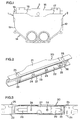
- Fig. 1 shows an apparatus for determining the volume of fuel being dispensed from a fuel pump unit.
- the Figure is a side view of two metering means 1, 2, whose metering casings 11, 12 are assembled in a common casing 14.
- Each of the metering means has a measuring chamber of its own with movable pistons which are connected to a shaft assembly.
- a frequency generator is connected to each shaft assembly for rotation therewith in the metering casing.
- the frequency generator is formed as a disk having a number of magnets around its periphery.
- the frequency generators are mounted on the respective shaft assemblies and arranged in the respective measuring chambers, i.e. in contact with the fuel.
- a pulse generator module 3 according to the invention is connected to the casing 14.
- the pulse generator module 3 is enclosed in a pulse generator casing 13 of plastic and has two connection points 16, 17 adjacent to the pulse generators 43, 44 for connection to the casing 14 adjacent to the frequency generators.
- the pulse generator casing has a metal cover 15 for preventing direct contact between the pulse generator casing 13 and the casing 14.
- the pulse generators are adapted to convert magnetic field changes which arise as the frequency generators rotate. It is important that the pulse generators are mounted in the vicinity of the frequency generators. It has been found very convenient to use magnets and hall effect sensors for contactless transmission of frequency signals between a frequency generator and a pulse generator.
- all movable components are arranged in the metering casing and all electronics that must be made explosion-proof are arranged in the pulse generator module.
- the pulse generator module shown in the embodiment is intended to have intrinsically safe electronics.
- Fig. 2 illustrates a case 20 which constitutes a first part of a pulse generator casing 13.
- the case 20 has an inside and an outside, of which the inside is shown.
- the case 20 comprises a covering 21, preferably of plastic, and an elongate chamber 22 formed of the covering 21.
- the chamber 22 has on the inside of the case 20 an opening directed from the covering 21, and the opening is partly surrounded by a flat surface 23 for a seal 27.
- the case 20 comprises engaging means in the form of pins 24, which are arranged in the chamber 22 on the inside of the covering 21 and extend through the opening of the chamber 22, projections 25 on the outside of the covering 21, and curved members 26, which, on the inside of the covering 21 adjacent to the projections 25 outside the chamber, extend in parallel with the pins 24.
- a lead-in 28 for an electric cable On one short side of the chamber 22 there is formed a lead-in 28 for an electric cable.
- Fig. 3 is a plan view of the inside of the part illustrated in Fig. 2 . Like parts have been given the same reference numerals.
- two recesses 29 are to be seen, which are formed of two portions where the covering is thinner.
- the two recesses 29 are each adapted to receive a pulse generator unit of a printed circuit.
- Fig. 4 illustrates a cover 30, which constitutes a second part of a pulse generator casing according to the invention and which fits the case 20.
- the side of the case 20 shown in Fig. 2 is adapted to fit the side of the cover 30, which is not shown in Fig. 3 , i.e. the inside of the cover 30.
- the cover 30 has a plate portion 31, whose not shown side is adapted to engage the flat surface 23 and the seal 27 surrounding the chamber 22 in the case 20. Side portions 23 extend along the long sides of the plate portion 31, perpendicularly thereto.
- the cover 30 comprises engaging means, in the form of apertures 35, 36, matching the engaging means 25, 26. There are also engaging means for the pins 24 on the not shown inside of the cover 30.
- annular holders 37 for switching means (not shown) in the form of magnets. Their function will be described in more detail below.
- Fig. 5 is a side view of the parts included in a pulse generator module 3 according the invention, separated from each other.
- the pulse generator module 3 comprises a case 20, a printed circuit assembly 40 which is adapted to be mounted in the chamber 22, a cover 30 and a seal 50. Moreover, two magnets 38 belonging to the cover are shown.
- the pulse generator module is mounted by inserting the printed circuit assembly 40 into the chamber 22 of the case 20.
- a cable (not shown) is connected to the printed circuit assembly 40 and is passed through the seal 50, which is arranged in the lead-in 28 formed in the chamber 22.
- the cover 30 is pressed against the case 20, whereby the engaging means 24, 25, 26 of the case 20 engage the corresponding engaging means 34, 35, 36 of the cover 30.
- a tight and explosion-proof pulse generator module is formed.
- the printed circuit assembly 40 comprises a holder 41 which holds and supports a printed circuit 42.
- the holder has a case side 47 and a cover side 48 and is resilient therebetween.
- the ends of the pins 24 preferably have a reduced diameter.
- the cover side 48 of the printed circuit holder rests against a shoulder in the transition between the different diameters of the pins.
- the printed circuit 42 which can be a flexible card, is thin and comprises two pulse generators 43 and 44, each comprising four hall effect generators which are adapted to successively register frequency signals in the form of changes in the magnetic field from a frequency generator.
- the printed circuit 42 further comprises a processor unit 45 which is connected to the two pulse generators 43, 44 and common thereto and which is positioned on the side of the printed circuit facing the cover 30.
- the processor unit has a calibration function, which will be described in more detail below, and a theft-detecting function, which gives a signal to a pump computer when detecting impermissible magnetic field changes, for instance when removing the pulse generator module from the frequency generator of metering means. Also information on the total volume dispensed through each of the metering means is stored in a memory unit on the printed circuit.
- the processor unit 45 accommodates a calibratable correction unit.
- the pulse generator unit functions to emit pulses via the cable (not shown) in response to movement of a frequency generator which is connected to one of the pulse generators.
- the processor unit 45 is put into calibration mode. In this mode, the correction unit will be calibrated for adaptation of the number of pulses which are to be emitted in relation to a given volume that has passed.
- the magnets 38 are again placed in the holders 37.
- the position of the magnets 38 in the holders 37 is sealable, which makes the calibration function convenient in commercial plants, in which the accuracy of the meters is checked regularly.
- a great advantage of using magnets for calibration signals is that signals are given in a contactless manner to the switching units and that no lead-in is required in the pulse generator casing.
- the chamber 22 has only one lead-in 28, it will be easier and less expensive to accomplish explosion protection by encapsulation, especially if two pulse generators are arranged to communicate via the same lead-in.
- the lines of the pulse generator module are laid in a common cable, and a seal is arranged in the lead-in round the cable.
- Pulse generator modules of the type described above can, with intrinsically safe electronics and the described hall effect sensors, advantageously be connected in series. For instance, five pulse generator modules can be connected to a common barrier for explosion protection via a common serial bus.
- the frequency generators and the pulse generators thus need not be arranged to communicate via magnetic fields, but they can communicate, for instance, in an acoustic, optical or inductive manner.
- the frequency generators can be arranged in the casing outside the measuring chamber and thus have no direct contact with the fuel.
Landscapes
- Engineering & Computer Science (AREA)
- Physics & Mathematics (AREA)
- Mathematical Physics (AREA)
- Theoretical Computer Science (AREA)
- Mechanical Engineering (AREA)
- Fluid Mechanics (AREA)
- General Physics & Mathematics (AREA)
- Measuring Volume Flow (AREA)
Description
- The present invention relates to an apparatus for volume determination in accordance with the preamble to claim 1.
- When measuring the volume of fuel dispensed from a fuel pump unit, it is common to let the fuel flow through a metering means, in which the fluid flow, via movable pistons in a measuring chamber in the metering means, causes a rotational movement. The rotational movement is then converted by a pulse generator, which emits electric pulses at a frequency which is proportional to the speed of the rotational movement. By means of these pulses, a calculating unit then controls a counter to indicate the volume dispensed.
- An example of an apparatus of this kind for measuring the volume of a flowing fluid is disclosed in Applicant's
WO 88/0851 - In this construction, the entire metering means, including its pulse generating means, is arranged in a common casing. The measuring chamber is separated by a partition from the pulse generating means located in a pulse generating chamber, and the frequency generator is adapted to follow the movement of the shaft assembly through a strong magnetic coupling acting transversely of the partition. The construction disclosed in
WO 88/08518 - As a rule, all equipment for handling vehicle fuels must be especially adapted to operate in an environment containing volatile and inflammable fluids. Every risk of explosion or ignition must be avoided, since the consequences, for instance at a gas station where large amounts of fuel are stored, can be disastrous.
- There are various methods for avoiding the risk of explosion. According to one method, use is made of such low energy levels that there is no risk of sparking. This is guaranteed by one or more explosion protection units, which constitute an explosion barrier and take care that no electricity on a safe side of the barrier has too high a level of energy. Components and wires connected on the safe side of such an explosion barrier are called intrinsically safe. The more components and the more energy-requiring components that are made intrinsically safe, the higher demands are placed on the barrier. As an example, it may be mentioned that the apparatus for optical transmission and reception between a frequency generator and a pulse generator has a requirement of energy which is great in the context.
- According to a further method, one tries to prevent every contact between on the one hand electricity and, on the other hand, fuel or fuel vapours by encapsulating electric conductors and components. Each unit containing electronics must be insulated from both flowing fuel and surrounding fuel vapours, if any, which in turn results in high costs. There are particular difficulties in the sealing round lead-ins in casings and partitions, e.g. for electric wires. There are still greater difficulties when sealing shaft openings for rotatable shafts.
- In the construction according to
WO 88/08518 - Although this construction has been found reliable, the partition construction, which comprises a chamber projecting towards the measuring chamber and holding a magnet, and a shaft unit having two bearings, is relatively complicated to manufacture. The entire magnetic coupling between the shaft assembly and the pulse generating means requires space and the use of relatively strong magnets for a reliable transmission of movement transversely of the partition panel. Moreover, the pulse generating chamber must be sealed by means of seals both towards the measuring chamber and outwards towards the surroundings in the fuel pump unit.
- It is common at gas stations to interconnect different fuel qualities in common pump units, for instance in such manner that gas having an optional octane rating can be obtained from the same dispenser, or in such manner that the same gas quality can be filled up from two different dispensers belonging to the same pump unit. To this end, it is usual to arrange two metering means, each comprising a pulse generating means, for the same pump unit. When two metering means of the above-mentioned type and their associated pulse generating means are mounted in the same pump unit, several cables are required, at the same time as several components in a common danger area must be made explosion-proof, which renders maintenance and satisfactory explosion-proofness difficult.
- In pump units for fuel it is desirable, in addition to the possibility of reading the dispensed volume for each filling operation, to have the possibility of reading the totally dispensed volume for each pump unit for checking the volumes sold and also reading the totally dispensed volume for each metering means for checking calibration and maintenance intervals. Today electronic total counters for the total volume sold are available, intended to be connected in pump units. These do not follow the respective metering means. Therefore, there is no information on the total volume dispensed from a separate metering means. Today, also special mechanical total counters are available for connection to the respective metering means. These mechanical counters follow the metering means and produce total volume data for the metering means specifically, independently of in which pump unit it is mounted. These mechanical counters are further subjected to wear. There will be particularly heavy wear if the counter is arranged at a distance from the metering means and if one transmits a rotational movement thereto, for instance through a wire, which is desirable in order to facilitate reading.
- A further inconvenience in the metering means that are available on the market today is fuel thefts, which can be committed by removing the pulse generator from the rest of the metering means. The pulse generator then cannot sense any movement and thus emits no pulses. To prevent the pulse generator from being removed, use is made of mechanical antitheft devices, e.g. padlocks. According to another technique, the pulse generator is mounted by means of bolts, whose head is broken off after mounting, which means that the pulse generator, when being removed, must be broken away from the rest of the metering means. Consequently, also the authorised staff must break away the pulse generator when maintenance is required, which, of course, renders maintenance difficult.
- One object of the invention is to eliminate or reduce the above-described drawbacks in the determining of the volume of fuel being dispensed from a fuel pump unit.
- A further object is to reduce the costs associated with explosion protection in connection with apparatus for measuring the volume of fuel, at the same time as equivalent or improved explosion protection is provided.
- A special object is to simplify the maintenance and the mounting of fuel metering means.
- According to the invention, these and other objects, which will appear from the following specification, have now been achieved by an apparatus which is of the type mentioned by way of introduction and which besides has the features defined in the characterising clause of claim 1.
- In the invention, the designation "pulse generating means" designates a means for converting movement into pulses. On the other hand, "pulse generator" concerns an apparatus which has the capacity of converting some sort of signals of a first frequency into pulses of the same frequency, or of a frequency corresponding to said first frequency. Thus, a pulse generator is included as part of a pulse generating means. The designation "frequency generator"- concerns a means for periodic movement, the frequency of the movement being detectable in some way.
- According to the invention, two metering means are arranged adjacent to each other. For generating pulses, each metering means has a frequency generator. The frequency generator is mounted in the metering casing, either in the metering casing of the respective mitering means or in a metering casing common to both metering means.
- A separate pulse generator module contains two pulse generators. The pulse generators are each connected to a frequency generator and are arranged to sense its movement in a contactless manner. The pulse generator module is encompassed in a separate pulse generator casing.
- By mounting two metering means together and letting the frequency generator of each metering means be mounted in the casing of the metering means at the same time as the pulse generators are arranged in a module of their own, an advantageous module system with exchangeable units is formed.
- By gathering two pulse generators in a module, manufacture as well as maintenance can be made simpler and, thus, less expensive. As an example, it may be mentioned that in case of an error in the pulse generator module, it is possible to simply exchange the entire module and thus quickly restore the pump-unit for operation. The defect module may then be taken care of separately.
- Since the pulse generator is adapted to sense in a contactless manner the movement of the frequency generator and, besides, is positioned in a separate casing, a division is rendered possible, in which moving parts and electronics are enclosed in separate casings.
- Moreover, it will be easier to make an inventive apparatus for determining a fuel volume explosion-proof, since the pulse generators are enclosed in a module of their own, which in itself allows a simplified explosion protection, and because two pulse generators are encompassed in the same separate casing, a common explosion protection can be provided, thereby almost halving the total cost for explosion protection. Further, it is of course safer to have a single explosion protection than to have a plurality of separate explosion protections for separate units.
- In a preferred embodiment of the invention, the frequency generators are encompassed in a measuring chamber, through which fuel flows, in the respective measuring casings. This eliminates the need of accomplishing a transmission of movement transversely of a tight partition. It is thus possible to simplify the design of the metering means on the pulse generator side. At the same time a tight closure of the metering casing on the pulse generator side is guaranteed in a simple manner. Furthermore, the transmission of movement between the shaft assembly of the metering means and the frequency generator is simplified.
- This preferred embodiment may also be considered as if the tight barrier between the pulse generating means and the measuring chamber has been moved from being positioned between the measuring chamber and the frequency generator to being positioned between the frequency generator and the pulse generator of the pulse generating means.
- An advantage of moving the tight barrier to be positioned between the frequency generator and the pulse generator is that it is easier to transmit in a contactless manner signals transversely of a tight barrier as compared with contactless transmission of movement transversely of a barrier.
- In a further preferred embodiment of the invention, the pulse generator module comprises a processor unit which is common to both pulse generators. This means that the cost of the pulse generator function can be reduced while saving space. -The pulse generator module can accommodate a total counter function for metering means as well as pump unit, in which case the respective total counters can easily be shown on the usual counter of the pump unit.
- In a further preferred embodiment, the module comprises a calibratable correction unit, and therefore correction of the number of pulses corresponding to a certain volume can be effected directly in the pulse generator module.
- In a particularly preferred embodiment, the frequency generators comprise magnets, which cause magnetic field changes when the frequency generators rotate. According to this embodiment, the pulse generators are adapted to convert the magnetic field changes into electric pulses.
- A great advantage of this embodiment is that the pulse generators sense magnetic field changes of another type when they are removed from the frequency generators. Thus, it is possible to register that the pulse generators are being removed, and therefore to interrupt or prevent the dispensing of fuel. It will thus be impossible to steel fuel by removing the pulse generators from the frequency generators. Also the need of complicated mechanical anti-theft devices is obviated.
- One more advantage of magnetic communication between frequency generator and pulse generator is that only low electric energy levels are required for operation of the pulse generators. This results in lower demands being placed on an explosion barrier to make the pulse generators intrinsically safe, which in turn results in cost savings.
- The invention will now be described in more detail with reference to the accompanying drawings, which illustrate a non-limiting embodiment, and in which
-
Fig. 1 is a side view of an apparatus for volume determination in a fuel pump unit according to the invention; -
Fig. 2 is a perspective view of a first part of a pulse generator casing according to the invention; -
Fig. 3 is a top plan view of the inside of the part shown inFig. 2 ; -
Fig. 4 is a perspective view of a second part of a pulse generator casing according to the invention; and -
Fig 5 is an exploded side view of a pulse generator module according to the invention and shows the components included therein. -
Fig. 1 shows an apparatus for determining the volume of fuel being dispensed from a fuel pump unit. The Figure is a side view of two metering means 1, 2, whosemetering casings common casing 14. Each of the metering means has a measuring chamber of its own with movable pistons which are connected to a shaft assembly. When fuel flows through the measuring chamber through inlet ducts and outlet ducts (not shown), the pistons are moved and the shaft assembly is rotated. A frequency generator is connected to each shaft assembly for rotation therewith in the metering casing. The frequency generator is formed as a disk having a number of magnets around its periphery. The frequency generators are mounted on the respective shaft assemblies and arranged in the respective measuring chambers, i.e. in contact with the fuel. - A
pulse generator module 3 according to the invention is connected to thecasing 14. Thepulse generator module 3 is enclosed in apulse generator casing 13 of plastic and has two connection points 16, 17 adjacent to thepulse generators casing 14 adjacent to the frequency generators. The pulse generator casing has ametal cover 15 for preventing direct contact between thepulse generator casing 13 and thecasing 14. - The pulse generators are adapted to convert magnetic field changes which arise as the frequency generators rotate. It is important that the pulse generators are mounted in the vicinity of the frequency generators. It has been found very convenient to use magnets and hall effect sensors for contactless transmission of frequency signals between a frequency generator and a pulse generator.
- It has been found advantageous to arrange four hall effect sensors after each other, such that each electromagnetic field change results in four successive pulses. As a result, a high resolution of each revolution is obtained for the frequency generator. For instance, 104 pulses can be obtained per revolution with 26 magnets arranged on the circumference of the frequency generator. The size of the frequency generator can thus be limited, which is a great advantage. One more advantage of four successive measurements is that the difficulties in steeling fuel by cheating the pulse generator will increase.
- In this embodiment, all movable components are arranged in the metering casing and all electronics that must be made explosion-proof are arranged in the pulse generator module. The pulse generator module shown in the embodiment is intended to have intrinsically safe electronics.
- A preferred embodiment of a pulse generator module will be described below with reference to
Figs 2-5 . -
Fig. 2 illustrates acase 20 which constitutes a first part of apulse generator casing 13. Thecase 20 has an inside and an outside, of which the inside is shown. Thecase 20 comprises a covering 21, preferably of plastic, and anelongate chamber 22 formed of thecovering 21. Thechamber 22 has on the inside of thecase 20 an opening directed from the covering 21, and the opening is partly surrounded by aflat surface 23 for aseal 27. - The
case 20 comprises engaging means in the form ofpins 24, which are arranged in thechamber 22 on the inside of the covering 21 and extend through the opening of thechamber 22,projections 25 on the outside of the covering 21, andcurved members 26, which, on the inside of the covering 21 adjacent to theprojections 25 outside the chamber, extend in parallel with thepins 24. - On one short side of the
chamber 22 there is formed a lead-in 28 for an electric cable. -
Fig. 3 is a plan view of the inside of the part illustrated inFig. 2 . Like parts have been given the same reference numerals. In addition to that shown inFig. 2 , tworecesses 29 are to be seen, which are formed of two portions where the covering is thinner. The tworecesses 29 are each adapted to receive a pulse generator unit of a printed circuit. By the material of the covering being thinner adjacent to the pulse generator units, the possibility of the pulse generators sensing in a contactless manner through the material is promoted. -
Fig. 4 illustrates acover 30, which constitutes a second part of a pulse generator casing according to the invention and which fits thecase 20. The side of thecase 20 shown inFig. 2 is adapted to fit the side of thecover 30, which is not shown inFig. 3 , i.e. the inside of thecover 30. - The
cover 30 has aplate portion 31, whose not shown side is adapted to engage theflat surface 23 and theseal 27 surrounding thechamber 22 in thecase 20.Side portions 23 extend along the long sides of theplate portion 31, perpendicularly thereto. - The
cover 30 comprises engaging means, in the form ofapertures means pins 24 on the not shown inside of thecover 30. - On the outside of the
cover 30, there are twoannular holders 37 for switching means (not shown) in the form of magnets. Their function will be described in more detail below. -
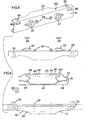
Fig. 5 is a side view of the parts included in apulse generator module 3 according the invention, separated from each other. Thepulse generator module 3 comprises acase 20, a printedcircuit assembly 40 which is adapted to be mounted in thechamber 22, acover 30 and aseal 50. Moreover, twomagnets 38 belonging to the cover are shown. - The pulse generator module is mounted by inserting the printed
circuit assembly 40 into thechamber 22 of thecase 20. A cable (not shown) is connected to the printedcircuit assembly 40 and is passed through theseal 50, which is arranged in the lead-in 28 formed in thechamber 22. Subsequently, thecover 30 is pressed against thecase 20, whereby the engagingmeans case 20 engage the corresponding engagingmeans cover 30. Thus, a tight and explosion-proof pulse generator module is formed. - The printed
circuit assembly 40 comprises aholder 41 which holds and supports a printedcircuit 42. The holder has acase side 47 and acover side 48 and is resilient therebetween. In thecover side 48 of the printed circuit holder there are twoapertures 49 for receiving the ends of thepins 24. The ends of thepins 24 preferably have a reduced diameter. Thecover side 48 of the printed circuit holder rests against a shoulder in the transition between the different diameters of the pins. - The printed
circuit 42, which can be a flexible card, is thin and comprises twopulse generators circuit 42 further comprises aprocessor unit 45 which is connected to the twopulse generators cover 30. The processor unit has a calibration function, which will be described in more detail below, and a theft-detecting function, which gives a signal to a pump computer when detecting impermissible magnetic field changes, for instance when removing the pulse generator module from the frequency generator of metering means. Also information on the total volume dispensed through each of the metering means is stored in a memory unit on the printed circuit. - Adjacent to the
processor unit 45 there are two switchingunits 46, which are adapted to sense the presence or absence of the switching means, i.e. themagnets 38, in theholders 37. - The
processor unit 45 accommodates a calibratable correction unit. When the switchingunits 46 sense the presence of themagnets 38, the pulse generator unit functions to emit pulses via the cable (not shown) in response to movement of a frequency generator which is connected to one of the pulse generators. When the switchingunits 46 sense the absence ofmagnets 38, theprocessor unit 45 is put into calibration mode. In this mode, the correction unit will be calibrated for adaptation of the number of pulses which are to be emitted in relation to a given volume that has passed. After completion of the calibration, themagnets 38 are again placed in theholders 37. The position of themagnets 38 in theholders 37 is sealable, which makes the calibration function convenient in commercial plants, in which the accuracy of the meters is checked regularly. A great advantage of using magnets for calibration signals is that signals are given in a contactless manner to the switching units and that no lead-in is required in the pulse generator casing. - Since the
chamber 22 has only one lead-in 28, it will be easier and less expensive to accomplish explosion protection by encapsulation, especially if two pulse generators are arranged to communicate via the same lead-in. Preferably, the lines of the pulse generator module are laid in a common cable, and a seal is arranged in the lead-in round the cable. - Pulse generator modules of the type described above can, with intrinsically safe electronics and the described hall effect sensors, advantageously be connected in series. For instance, five pulse generator modules can be connected to a common barrier for explosion protection via a common serial bus.
- The invention is not limited to the embodiment described above, but several modifications are feasible within the scope of protection according to the accompanying claims.
- The frequency generators and the pulse generators thus need not be arranged to communicate via magnetic fields, but they can communicate, for instance, in an acoustic, optical or inductive manner.
- The frequency generators can be arranged in the casing outside the measuring chamber and thus have no direct contact with the fuel.
Claims (10)
- An apparatus for volume determination in a fuel pump unit, said apparatus having a first metering means (1) which comprises
a metering casing (11) having a shaft assembly, which is enclosed therein and which is adapted to be rotated when fuel flows through the metering casing, and
a pulse generating means (3) which is adapted to convert the rotation of the shaft assembly into pulses and which comprises a frequency generator and a pulse generator (43, 44), the frequency generator being connected to the shaft assembly to be rotated therewith, and the pulse generator (43, 44) being adapted to sense, in a contactless manner, rotation of the frequency generator and to emit pulses in relation thereto,
characterised in
that the apparatus comprises a second metering means (2), whose construction and function correspond to the construction and function of the first metering means (1), the first and second metering means (1, 2) being arranged adjacent to one another,
that the frequency generators of the metering means (1, 2) are mounted in the respective metering casings (11, 12), and
that the two pulse generators (43, 44) are together arranged in a separate pulse generator module (3) and are encompassed in a pulse generator casing (13) which is detachably connected to said metering casings (11,12). - The apparatus as claimed in claim 1, wherein the frequency generators of the metering means (1, 2) are encompassed in a measuring chamber, through which fuel flows, in the respective metering casings (11, 12).
- The apparatus as claimed in claim 1 or 2, wherein the pulse generator module comprises a processor unit (45), which is common to both pulse generators (43, 44).
- The apparatus as claimed in any one of claims 1-3, wherein the frequency generators comprise magnets, which, as the frequency generators rotate, cause magnetic field changes, and the pulse generators (43, 44) are adapted to convert magnetic field changes into electric pulses.
- The apparatus as claimed in any one of the preceding claims,
wherein switching means (38) are arranged on the outside of the pulse generator casing (13), one pulse generator (43, 44) being associated with each switching means (38) for switching the pulse generator between different modes. - The apparatus as claimed in claim 5, wherein each switching means (38) is adapted to actuate an associated switching unit (48) through the wall (31) of the pulse generator casing (13) without any lead-in formed in the wall (31).
- The apparatus as claimed in any one of the preceding claims,
wherein the pulse generator module (3) comprises
a correcting means which is calibratable for each pulse generator belonging to the pulse generator module (3). - The apparatus as claimed in any one of the preceding claims,
wherein the pulse generator module (3) is a per se exchangeable unit, in which electronics connected to the metering means (1, 2) are enclosed. - The apparatus as claimed in any one of the preceding claims,
wherein the metering casings (11, 12) of said two metering means (1, 2) are integrated in a common casing. - The apparatus as claimed in any one of the preceding claims,
wherein said pulse generator module (3) is enclosed in a casing (13) for connection to at least two metering means (1, 2), and comprises means (43, 44) for sensing, simultaneously and in a contactless manner, flow-induced movement of each of at least two frequency generators arranged outside the casing (13), and for emitting electric pulses in response to the movement of the frequency generators.
Applications Claiming Priority (3)
| Application Number | Priority Date | Filing Date | Title |
|---|---|---|---|
| SE9604076 | 1996-11-07 | ||
| SE9604076A SE511179C2 (en) | 1996-11-07 | 1996-11-07 | Device for volume determination |
| PCT/SE1997/001863 WO1998020305A1 (en) | 1996-11-07 | 1997-11-07 | Apparatus for volume determination |
Publications (2)
| Publication Number | Publication Date |
|---|---|
| EP1019676A1 EP1019676A1 (en) | 2000-07-19 |
| EP1019676B1 true EP1019676B1 (en) | 2014-09-17 |
Family
ID=20404528
Family Applications (1)
| Application Number | Title | Priority Date | Filing Date |
|---|---|---|---|
| EP97913591.0A Expired - Lifetime EP1019676B1 (en) | 1996-11-07 | 1997-11-07 | Apparatus for volume determination |
Country Status (5)
| Country | Link |
|---|---|
| US (1) | US5869757A (en) |
| EP (1) | EP1019676B1 (en) |
| AU (1) | AU5073798A (en) |
| SE (1) | SE511179C2 (en) |
| WO (1) | WO1998020305A1 (en) |
Families Citing this family (2)
| Publication number | Priority date | Publication date | Assignee | Title |
|---|---|---|---|---|
| RU2157968C2 (en) * | 1998-04-27 | 2000-10-20 | Курский государственный технический университет | Water meter |
| SE513441C2 (en) * | 1999-01-28 | 2000-09-11 | Dresser Wayne Ab | Measuring means for fuel pumps and ways of measuring the output of fuel from a fuel pump |
Family Cites Families (7)
| Publication number | Priority date | Publication date | Assignee | Title |
|---|---|---|---|---|
| US2936096A (en) * | 1958-02-21 | 1960-05-10 | Sun Oil Co | Fuel dispensing system |
| JPS54177960U (en) * | 1978-06-02 | 1979-12-15 | ||
| SE460929B (en) * | 1987-04-24 | 1989-12-04 | Dresser Wayne Ab | SET AND DEVICE MEASURING THE VOLUME OF A VOLUME THAT FLOWS THROUGH A MEETING CHAMBER DURING A MEASURING PERIOD |
| DK160059C (en) * | 1987-11-13 | 1991-06-10 | Torben Bruno Rasmussen | GAS FLOW METER FOR HOUSEHOLD USE |
| WO1993006439A1 (en) * | 1991-09-23 | 1993-04-01 | Futureflo System, Incorporated | Liquid flow meter |
| US5509305A (en) * | 1992-02-12 | 1996-04-23 | Daniel Industries, Inc. | Closely coupled, dual turbine volumetric flow meter |
| US5557084A (en) * | 1994-07-22 | 1996-09-17 | Gilbarco Inc. | Temperature compensating fuel dispenser |
-
1996
- 1996-11-07 SE SE9604076A patent/SE511179C2/en not_active IP Right Cessation
-
1997
- 1997-11-06 US US08/964,380 patent/US5869757A/en not_active Expired - Lifetime
- 1997-11-07 AU AU50737/98A patent/AU5073798A/en not_active Abandoned
- 1997-11-07 EP EP97913591.0A patent/EP1019676B1/en not_active Expired - Lifetime
- 1997-11-07 WO PCT/SE1997/001863 patent/WO1998020305A1/en not_active Ceased
Also Published As
| Publication number | Publication date |
|---|---|
| AU5073798A (en) | 1998-05-29 |
| EP1019676A1 (en) | 2000-07-19 |
| SE9604076D0 (en) | 1996-11-07 |
| US5869757A (en) | 1999-02-09 |
| WO1998020305A1 (en) | 1998-05-14 |
| SE9604076L (en) | 1998-05-08 |
| SE511179C2 (en) | 1999-08-16 |
Similar Documents
| Publication | Publication Date | Title |
|---|---|---|
| US9356334B2 (en) | Meter register transmitting flow rate warning | |
| DK1875171T3 (en) | SYSTEM AND PROCEDURE FOR TRANSMISSION OF CONSUMER TARGET DATA FROM A SUPPLY SERVICE METER TO A REMOTE SURVEILLANCE SITE | |
| US4410949A (en) | Controller for fuel dispenser | |
| US9302899B2 (en) | Fuel dispenser flow meter fraud detection and prevention | |
| US6336362B1 (en) | Method and system for measuring and remotely reporting the liquid level of tanks and the usage thereof | |
| US4345146A (en) | Apparatus and method for an electronic identification, actuation and recording system | |
| US4888706A (en) | Fluid distribution to multiple users through distributed intelligence sub-centers | |
| US20140260514A1 (en) | Fuel Dispenser Flow Meter Fraud Detection and Prevention | |
| WO1997016705A1 (en) | Detection system for a flowmeter | |
| CN109579947A (en) | Liquid level of liquefied petroleum gas measuring system | |
| US5869757A (en) | Apparatus for volume determination | |
| US7728606B2 (en) | Measurement instrument | |
| EP0717286A2 (en) | Commodity consumption meters | |
| EP2962075B1 (en) | Liquid level gauge device | |
| CN217083844U (en) | Ultrasonic flowmeter | |
| US7398188B2 (en) | Apparatus for determining and/or monitoring a physical or chemical quantity | |
| KR102771284B1 (en) | Mechanical water meter with both remote and visual meter reading | |
| Chien | Short-Range Radio Transmission Of Sensor Data | |
| IL167464A (en) | Antenna and meter register including same | |
| MXPA97007026A (en) | Cable entry sealed to accommodate instrument and sell method | |
| JPH05201495A (en) | Identification device |
Legal Events
| Date | Code | Title | Description |
|---|---|---|---|
| PUAI | Public reference made under article 153(3) epc to a published international application that has entered the european phase |
Free format text: ORIGINAL CODE: 0009012 |
|
| 17P | Request for examination filed |
Effective date: 19990510 |
|
| AK | Designated contracting states |
Kind code of ref document: A1 Designated state(s): DE FR GB IT SE |
|
| 17Q | First examination report despatched |
Effective date: 20071029 |
|
| RAP1 | Party data changed (applicant data changed or rights of an application transferred) |
Owner name: DRESSER WAYNE AB |
|
| GRAP | Despatch of communication of intention to grant a patent |
Free format text: ORIGINAL CODE: EPIDOSNIGR1 |
|
| RIC1 | Information provided on ipc code assigned before grant |
Ipc: G01F 1/075 20060101AFI20140313BHEP |
|
| INTG | Intention to grant announced |
Effective date: 20140414 |
|
| GRAS | Grant fee paid |
Free format text: ORIGINAL CODE: EPIDOSNIGR3 |
|
| GRAA | (expected) grant |
Free format text: ORIGINAL CODE: 0009210 |
|
| AK | Designated contracting states |
Kind code of ref document: B1 Designated state(s): DE FR GB IT SE |
|
| REG | Reference to a national code |
Ref country code: GB Ref legal event code: FG4D |
|
| REG | Reference to a national code |
Ref country code: DE Ref legal event code: R096 Ref document number: 69740735 Country of ref document: DE Effective date: 20141023 |
|
| RAP2 | Party data changed (patent owner data changed or rights of a patent transferred) |
Owner name: WAYNE FUELING SYSTEMS SWEDEN AB |
|
| REG | Reference to a national code |
Ref country code: DE Ref legal event code: R081 Ref document number: 69740735 Country of ref document: DE Owner name: WAYNE FUELING SYSTEMS SWEDEN AB, SE Free format text: FORMER OWNER: DRESSER WAYNE AB, MALMOE, SE Effective date: 20140917 Ref country code: DE Ref legal event code: R081 Ref document number: 69740735 Country of ref document: DE Owner name: WAYNE FUELING SYSTEMS SWEDEN AB, SE Free format text: FORMER OWNER: DRESSER WAYNE AB, MALMOE, SE Effective date: 20141204 |
|
| PG25 | Lapsed in a contracting state [announced via postgrant information from national office to epo] |
Ref country code: SE Free format text: LAPSE BECAUSE OF FAILURE TO SUBMIT A TRANSLATION OF THE DESCRIPTION OR TO PAY THE FEE WITHIN THE PRESCRIBED TIME-LIMIT Effective date: 20140917 |
|
| REG | Reference to a national code |
Ref country code: DE Ref legal event code: R097 Ref document number: 69740735 Country of ref document: DE |
|
| PLBE | No opposition filed within time limit |
Free format text: ORIGINAL CODE: 0009261 |
|
| STAA | Information on the status of an ep patent application or granted ep patent |
Free format text: STATUS: NO OPPOSITION FILED WITHIN TIME LIMIT |
|
| 26N | No opposition filed |
Effective date: 20150618 |
|
| PG25 | Lapsed in a contracting state [announced via postgrant information from national office to epo] |
Ref country code: IT Free format text: LAPSE BECAUSE OF FAILURE TO SUBMIT A TRANSLATION OF THE DESCRIPTION OR TO PAY THE FEE WITHIN THE PRESCRIBED TIME-LIMIT Effective date: 20140917 |
|
| REG | Reference to a national code |
Ref country code: FR Ref legal event code: PLFP Year of fee payment: 19 |
|
| PGFP | Annual fee paid to national office [announced via postgrant information from national office to epo] |
Ref country code: GB Payment date: 20151104 Year of fee payment: 19 Ref country code: DE Payment date: 20151103 Year of fee payment: 19 |
|
| PGFP | Annual fee paid to national office [announced via postgrant information from national office to epo] |
Ref country code: FR Payment date: 20151106 Year of fee payment: 19 |
|
| REG | Reference to a national code |
Ref country code: DE Ref legal event code: R119 Ref document number: 69740735 Country of ref document: DE |
|
| GBPC | Gb: european patent ceased through non-payment of renewal fee |
Effective date: 20161107 |
|
| REG | Reference to a national code |
Ref country code: FR Ref legal event code: ST Effective date: 20170731 |
|
| PG25 | Lapsed in a contracting state [announced via postgrant information from national office to epo] |
Ref country code: FR Free format text: LAPSE BECAUSE OF NON-PAYMENT OF DUE FEES Effective date: 20161130 |
|
| PG25 | Lapsed in a contracting state [announced via postgrant information from national office to epo] |
Ref country code: DE Free format text: LAPSE BECAUSE OF NON-PAYMENT OF DUE FEES Effective date: 20170601 Ref country code: GB Free format text: LAPSE BECAUSE OF NON-PAYMENT OF DUE FEES Effective date: 20161107 |