EP1019127B1 - Aerosol medication delivery apparatus - Google Patents
Aerosol medication delivery apparatus Download PDFInfo
- Publication number
- EP1019127B1 EP1019127B1 EP98946684A EP98946684A EP1019127B1 EP 1019127 B1 EP1019127 B1 EP 1019127B1 EP 98946684 A EP98946684 A EP 98946684A EP 98946684 A EP98946684 A EP 98946684A EP 1019127 B1 EP1019127 B1 EP 1019127B1
- Authority
- EP
- European Patent Office
- Prior art keywords
- canister
- medication
- chamber housing
- delivery apparatus
- aerosol
- Prior art date
- Legal status (The legal status is an assumption and is not a legal conclusion. Google has not performed a legal analysis and makes no representation as to the accuracy of the status listed.)
- Expired - Lifetime
Links
Images
Classifications
-
- A—HUMAN NECESSITIES
- A61—MEDICAL OR VETERINARY SCIENCE; HYGIENE
- A61M—DEVICES FOR INTRODUCING MEDIA INTO, OR ONTO, THE BODY; DEVICES FOR TRANSDUCING BODY MEDIA OR FOR TAKING MEDIA FROM THE BODY; DEVICES FOR PRODUCING OR ENDING SLEEP OR STUPOR
- A61M15/00—Inhalators
- A61M15/0086—Inhalation chambers
-
- A—HUMAN NECESSITIES
- A61—MEDICAL OR VETERINARY SCIENCE; HYGIENE
- A61M—DEVICES FOR INTRODUCING MEDIA INTO, OR ONTO, THE BODY; DEVICES FOR TRANSDUCING BODY MEDIA OR FOR TAKING MEDIA FROM THE BODY; DEVICES FOR PRODUCING OR ENDING SLEEP OR STUPOR
- A61M11/00—Sprayers or atomisers specially adapted for therapeutic purposes
- A61M11/001—Particle size control
- A61M11/002—Particle size control by flow deviation causing inertial separation of transported particles
-
- A—HUMAN NECESSITIES
- A61—MEDICAL OR VETERINARY SCIENCE; HYGIENE
- A61M—DEVICES FOR INTRODUCING MEDIA INTO, OR ONTO, THE BODY; DEVICES FOR TRANSDUCING BODY MEDIA OR FOR TAKING MEDIA FROM THE BODY; DEVICES FOR PRODUCING OR ENDING SLEEP OR STUPOR
- A61M11/00—Sprayers or atomisers specially adapted for therapeutic purposes
- A61M11/001—Particle size control
- A61M11/003—Particle size control by passing the aerosol trough sieves or filters
-
- A—HUMAN NECESSITIES
- A61—MEDICAL OR VETERINARY SCIENCE; HYGIENE
- A61M—DEVICES FOR INTRODUCING MEDIA INTO, OR ONTO, THE BODY; DEVICES FOR TRANSDUCING BODY MEDIA OR FOR TAKING MEDIA FROM THE BODY; DEVICES FOR PRODUCING OR ENDING SLEEP OR STUPOR
- A61M15/00—Inhalators
- A61M15/009—Inhalators using medicine packages with incorporated spraying means, e.g. aerosol cans
Definitions
- the present invention relates to an aerosol medication delivery apparatus as disclosed in the preambles of claims 1 and 8.
- An aerosol medication delivery apparatus of this type which is used for administering a desired respirable dosage of a medication in aerosol form to a patient's lungs by oral inhalation is described in US-A-5,012,804.
- the known apparatus includes a cylindrical body useable with different inlet and outlet fittings at the opposite ends thereof.
- the outlet end is provided with a spider forming a support for a thin diaphragm acting as an inhalation valve. All portions of the spider extend straight and radially with respect to the cylindrical body.
- US-A-3,236,458 describes an aerosol apparatus having a containment chamber provided adjacent to the outlet end thereof with a disk having a convex surface facing the jet of aerosols.
- the disk is sufficiently spaced from a distal wall of the containment chamber and has a diameter which is substantially equal to a diameter of an opening within the distal wall providing a tortuous path for all gas leaving the output end of the containment chamber. This measure will increase the pressure drop and is difficult to manufacture.
- Conventional aerosol medication delivery systems include pressurized metered-dose inhalers (pMDIs).
- pMDIs typically have two components: a canister component in which the medication particles are stored under pressure in a suspension or solution form and a receptacle component used to hold and actuate the canister.
- the canister component typically includes a valved outlet from which the contents of the canister can be discharged. Aerosol medication is dispensed from the pMDI by applying a force on the canister component to push it into the receptacle component thereby opening the valved outlet and causing the medication particles to be conveyed from the valved outlet through the receptacle component and discharged from an outlet of the receptacle component.
- the medication particles Upon discharge from the canister, the medication particles are "atomized" forming an aerosol. It is intended that the patient coordinate the discharge of aerosolized medication with his or her inhalation so that the medication particles are entrained in the patient's inspiratory flow and conveyed to the lungs.
- propellants such as chlorofluorocarbons (CFCs)
- CFCs chlorofluorocarbons
- the high velocity of the aerosol medication particles may also accentuate the difficulty of a significant number of patients. particularly the very young and elderly, to coordinate actuation of the pMDI with inhalation of the aerosol medication particles generated. Failure to coordinate the actuation and inhalation maneuvers and failure to inhale slowly, have been documented by the literature [S.P. Newman, "Aerosol Deposition Considerations in Inhalation Therapy” Chest / 88 / 2 / August. 1985 / Supplement] as contributing to a significant reduction in the number of aerosol medication particles inspired and deposited in a patient's lungs.
- Impaction and deposition of aerosol medication particles on a patient's oropharynx and upper airway may also contribute to an unpleasant taste in a patient's mouth, particularly with certain medication solution or suspension formulations such as flunisolide.
- [t is a further object to provide a device that reduces the delivery of non-respirable medication particles from a pMDI canister to a patient.
- the aerosol medication delivery apparatus can include a canister-holding portion and a chamber housing.
- the canister-holding portion has a receptacle for receipt of a pMDI canister containing a medication and a propellant.
- the canister-holding portion has a discharge orifice communicating with the receptacle to direct an aerosol into an interior of the chamber housing at an input end thereof.
- the chamber housing also has an output end from which medication can be withdrawn by inhalation by a patient.
- the canister-holding portion and the chamber housing are coupled together by a mechanism that provides for the canister-holding portion to be retracted into the chamber housing for storage.
- the coupling mechanism also allows the canister-holding portion to be extracted from its storage position in the chamber housing and pivoted into position for use when dispensing medication.
- an aerosol medication delivery apparatus in another aspect, includes a chamber housing with an input end an output end. The input end receives the discharge of a medication from a pMDI canister which is received in an elastomeric backpiece that is adapted to accommodate various sizes of actuator boot mouthpieces.
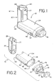
- FIGS. 1 - 11 show an embodiment of an aerosol medication delivery apparatus 10.
- the apparatus 10 comprises a pMDI canister-holding portion (or dispenser) 22 coupled to a chamber housing portion 24.
- the delivery apparatus 10 together with a pMDI canister 30 form an aerosol therapy system 12.
- the canister-holding portion 22 has a generally rectangular cross-sectional shape that defines a receiving area or receptacle 28 for receipt therein of the pMDI canister 30.
- the receiving area 28 is suited for conventional pMDI canisters of well-known construction.
- the pMDI canister 30 contains a medication suspension or solution under pressure. In the present embodiment, an HFA propelled medication suspension or solution formulation is used. In one embodiment, the liquid medication is flunisolide. Other propellants and other medications may also be used.
- the pMDI canister 30 has a stem 32 that permits a portion of the medication suspension or solution to be discharged therefrom upon application of a force on the stem 32.
- the canister stem 32 is positioned in a vertical channel or well 34 formed in the bottom of the canister-holding portion 22.
- ambient air can pass into the chamber via a passageway 33.
- a horizontal passage 35 communicates with the vertical channel 34.
- the horizontal passage 35 leads to a discharge orifice 36 located opposite from the vertical channel 34.
- the discharge orifice 36 forms the passage by which medication particles from the pMDI canister 30 can exit the canister holding portion 22 and enter into the chamber housing portion 24.
- the chamber housing 24 has an input end 46 and an output end 48 that define the ends of an interior space 39.
- the chamber housing portion 24 is formed of two parts: a main housing portion 43 and a downstream portion 45.
- the main housing portion 43 and the downstream portion 45 together define the interior space 39 of the chamber housing portion 24.
- the downstream portion 45 has retaining fingers 47 that engage in slots 49 on each side of the main housing portion 43. In the embodiment shown, the main housing portion 43 and the downstream portion 45 easily snap together and can be easily disconnected for cleaning.
- the main housing portion 43 has a curved cross section.
- the curved cross-section has a complex geometry formed of a plurality of radii to form a convenient, easy-to-use shape.
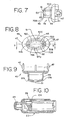
- a containment baffle 51 is located in the downstream portion 45 at the outlet of the chamber housing 24.
- the containment baffle 51 is located centrally and forms a distal wall 53 of the downstream portion 45.
- the containment baffle 51 is positioned so as to partially block the output end 48.
- the containment baffle 51 reduces the velocity or flow rate or both of the aerosol medication particles on axis 42 of the chamber housing 24.
- a mouthpiece 55 is located on the outside of the downstream portion 45 and includes the containment baffle 51 at an outlet end thereof.
- the containment baffle 51 has a concave-shaped center portion 62.
- the perimeter of the concave-shaped center portion 62 of the containment baffle 51 has generally straight vertical sides 57A and 57B, a curved top side 57C, and a curved bottom side 57D.
- the perimeter of the concave-shaped center portion 62 of the containment baffle 51 conforms generally in shape to the cross-sectional shape of the mouthpiece 55.
- the concave-shaped center portion 62 of the containment baffle 51 is aligned with a central axis 42 of the chamber housing 24 and is directly in line with the discharge orifice 36.
- Aerosol medication particles that have a flow path away from the axis of symmetry 42 tend to have a velocity that is lower than that of particles near to the axis of symmetry.
- the center portion 62 of the containment baffle 51 reduces the forward, on-axis velocity and simultaneously acts as an impaction surface for on-axis projectile aerosol medication particles.
- the center portion 62 allows slower moving aerosol medication particles to migrate towards the sides 52 of the chamber housing 24.
- the forward velocity of the aerosol medication particles away from the axis 42 along the chamber length is also reduced by the outer portion 66 of the containment baffle 51 that is concentric with the concave shaped center portion 62.
- the inhalation opening area 70 is Positioned between the center and outer portions 62 and 66 is an inhalation opening area 70.
- the inhalation opening area 70 is defined by four openings 70A-70D.
- the openings are arcuate in shape and conform to the periphery of the central portion 62.
- Each of the openings 70 has a length of approximately 9 mm and a width of approximately 2 mm. The size, shape and number of openings may vary depending on the medication suspension or solution formulation and/or propellant used.
- the aerosol delivery apparatus 10 includes a cap 74 which can be placed over the mouthpiece 55 to prevent contaminants from entering the interior space 39.
- the cap 74 serves to protect the mouthpiece 55 and keep it relatively clean.
- the canister-holding portion 22 and chamber housing 24 are arranged as shown in FIG. 1.
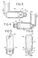
- the cap 74 is removed and the pMDI canister 30 is located in the receiving area 28 with the stem 32 inserted into the channel 34 formed in the bottom of the receiving area 28 as shown in FIG. 6.
- the apparatus 10 receives the pMDI canister 30 which is operated conventionally (i.e. by pressing down on the pMDI canister 30 which is located stem-side-down in the receiving area 28).
- the medication suspension or solution formulation in the pMDI canister 30 is discharged out of an opening 33 at the tip of the stem 32.
- the propellant and suspending liquid or solvent evaporate and the medication particles are discharged in aerosol form into the surrounding environment inside the chamber volume 39.
- the medication particles in the aerosol plume may have an average speed, size distribution and/or flow rate that may not be ideal for direct inhalation by a patient.
- the proportion of larger non-respirable particles available on inhalation is minimized and the dose of respirable particles is optimized.
- the aerosol medication particles are withdrawn therefrom by having the patient, whose mouth is around the mouthpiece 55, inhale through the inhalation opening area 70. The aerosol medication particles will then flow through the inhalation opening area 70 and into the patient's mouth.
- a further feature of the aerosol medication apparatus 10 is that it can be retracted for convenient storage and portability.
- the chamber housing 24 is coupled to the canister-holding portion 22 via a coupling mechanism 94 as shown in FIG. 11.
- the coupling mechanism 94 permits the aerosol medication delivery apparatus 10 to be compactly stored by pivoting the canister-holding portion 22 from the position of FIGS. 1-4 to a horizontal position and then pushing the canister-holding portion 22 so that it translationally moves into the chamber housing 24 as shown in FIG. 10.
- the coupling mechanism 94 includes a pair of slots 96 formed in the chamber housing 24, wherein each slot 96 has an open end 98 and a closed end 100.
- the canister-holding portion 22 has a pair of pegs 102. attached thereto.
- the interior portion of the chamber housing 24 has multiple parallel tracks 104 (shown in FIG. 10) which guide the canister-holding portion 22 into the chamber housing 24.
- a top end 109 of the canister-holding portion 22 is first inserted into the output end 48 of the chamber housing 24 and translationally moved towards and past the input end 46 so that the pegs 102 are inserted into the open ends 98 of the corresponding slots 96. Each of the pegs 102 can then translationally move within its respective slot 96 to the closed end 100 thereof.
- the canister-holding portion 22 is telescopically received within the chamber housing 24 during translational movement and is able to move from the retracted position of FIG. 10 to an extended position.
- both pegs 102 contact the closed ends 100 of their corresponding slots 96 and the canister-holding portion 22 is then allowed to pivot to the position of FIG. 4 so that the patient can use the apparatus 10.
- the end of the canister-holding portion 22 is curved so as to allow it to pivot relative to the chamber housing 24.
- a plurality of ribs 77 may be located along the front and rear sides of the canister-holding portion 22 close to the top edge 109 thereof. These ribs 77 remain exposed when the canister-holding portion 22 is retracted into the chamber portion 24 so that the patient can use these ribs to help grip the end of the canister-holding portion 22 in order to withdraw it from the chamber portion 24. After use by the patient, the cap 74 can be placed back over the mouthpiece 55.
- the end result of combining the specified inhalation opening area 70, the chamber housing 24, and the containment baffle 51 is to administer a controllable and desired respirable dose of aerosol medication to a patient for inhalation into the lungs.
- the disclosed embodiment provides advantages over prior devices in that it incorporates an integrated actuator and is easier to use and is easier to store and carry given its smaller size.
- the containment baffle 51 An advantageous feature of the disclosed embodiment is provided by the containment baffle 51.
- the velocity of the aerosol medication particles nearest the axis of symmetry 42 will typically be greater than that of aerosol medication particles that are located further from the axis 42.
- the velocity of the aerosol medication particles near the axis 42 may be so large as to reduce the effectiveness of delivering the medication to the patient because it will cause a significant portion of the aerosol medication particles to impact on the oropharyngeal region and upper airway where they have no therapeutic value and, in the case of medication such as corticosteroids. may give rise to adverse side-effects.
- the containment baffle 51 overcomes this potential problem by isolating the patient's mouth from the location at which the greatest risk of high velocity impaction may occur.
- the containment baffle provides this solution in a manner that is relatively inexpensive and easy to manufacture.
- the disclosed aerosol medication delivery apparatus optimizes the deposition of respirable aerosol medication particles in a patient's lungs to provide a desired therapeutic effect.
- the aerosol medication delivery apparatus also reduces the importance of coordination between the actuation and inhalation maneuvers and reduces or eliminates possible side-effects caused by aerosol medication formulations consisting of corticosteroids.
- the aerosol medication delivery apparatus also reduces or eliminates the unpleasant taste associated with aerosol medication formulations such as flunisolide and allows for convenient portability and quick use.
- the present embodiment provides a particular advantage.
- the respirable dosage of flunisolide delivered to the patient can be controlled in a manner to closely conform to the dosage of flunisolide that had been delivered using conventional prior art systems that used prior propellants, such as CFC. In this manner, the dosage of flunisolide can be consistently maintained, thereby benefiting administration of such medication to patients.
- the shape, size, and number of openings in the inhalation opening area may vary in order to ensure the administration of a desired respirable dose of a specific pMDI formulation.
- the on-axis aerosol medication particles which are generally non-respirable and have a higher inertia than the respirable particles, collide with the interior center portion of the containment baffle resulting in a reduction in the number of larger (non-respirable) aerosol medication particles, and the division of larger (non-respirable) aerosol medication particles into smaller respirable particles.
- the containment baffle By sealing off (except for the inhalation opening area) the output end of the chamber, the containment baffle contributes to maintaining a high pressure zone in the chamber which allows for the deflection of most slower moving respirable aerosol medication particles away from the containment baffle and into the chamber for containment until inhaled by the patient through the inhalation opening area.
- the containment of the respirable aerosol medication particles in the chamber provides the patient with more time to inhale the aerosol medication particles and, therefore, reduces the importance of exact coordination between the discharge maneuver and inhalation.
- the canister-holding portion 22 is approximately 7.5 cm in height and is approximately 2.5 by 2.5 cm in cross section.
- the chamber housing 24 is approximately 8 cm in length and has an oval-shaped cross section with dimensions of approximately 49 mm by 33 mm.
- the mouthpiece 55 is approximately 1.5 cm in length.
- the canister-holding portion, the chamber housing, and the end cap are formed of a suitable hard, durable plastic, such as polypropylene.
- the discharge orifice 36 has a diameter of approximately 0.011 inches.
- the containment baffle 51 has a width of approximately 27 mm and a height of approximately 15 mm at the center and 5 mm at the side edges.
- the pMDI canister contains a 0.06% w/v to 0.24% w/v mixture of liquid medication, such as flunisolide in ethanolic solution and HFA as a propellant. It is understood that the pMDI canister 30 can also contain other liquids and other mixtures without departing from the spirit of the invention.
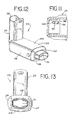
- FIGS. 12 and 13 another embodiment of an aerosol delivery apparatus 110 is shown. This embodiment is similar to the embodiment shown in FIGS. 1-11 and like components are labeled with the same numerals.
- the containment baffle 151 is located at an upstream end of the passageway defined in the mouthpiece 55.
- the containment baffle 151 in this embodiment is convex in shape and diverts flow around an on-axis trajectory.
- a chamber housing 124 has four squared-off sides 125, 126, 127, and 128. The squared-off sides may facilitate gripping of the device.
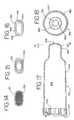
- a containment baffle 251 has a screen-like structure forming a plurality of openings defined between a crisscrossed mesh 252.
- the surface area provided by the mesh 252, combined with the relatively small areas of the openings. serves to prevent aerosol particles having a high velocity from passing to the patient.
- a containment baffle 351 has a plurality of small circular openings formed around a periphery of a solid central portion 362.
- the embodiment of FIG. 15 provides a surface area 362. combined with the relatively small openings, serves to prevent aerosol particles having a high velocity from passing to the patient.
- a containment baffle 451 has four relatively large openings formed around the periphery a solid dish-shaped central portion 462.
- the dish-shaped central portion 462 is connected to the remainder of the chamber body by one or more ribs 463.
- the embodiment of FIG. 16 provides a surface area 462, that serves to prevent aerosol particles having a high velocity from passing to the patient.
- FIGS. 17 and 18 there is shown an alternate embodiment 510 of an aerosol delivery apparatus.
- the embodiment of FIGS. 17 and 18 includes an aerosol delivery apparatus 510.
- the apparatus 510 includes a chamber housing 524 which defines an interior space 539.
- the apparatus 510 does not include an integrated canister-holding portion.
- the chamber housing 524 has a backpiece 527.
- the backpiece 527 is made of an elastomeric material and is fitted over the upstream end of the chamber housing 524.
- the backpiece 527 has an opening 529 located centrally therein. The opening 529 is sized to receive the mouthpiece end of a separate pMDI actuator boot.
- the opening 529 is sized so that the mouthpiece of the pMDI actuator boot fits snugly into the opening 529. Because the backpiece 527 is formed of an elastomeric material, it is resilient and the opening 529 in the backpiece can be stretched. thereby enabling it accommodate actuator boot mouthpieces of various sizes and shapes.
- the backpiece 527 may be similar to the backpiece described in U.S. Pat. No. 4,470.412 or in Ser. No. 08/248,716, the entire disclosure of which is incorporated by reference herein.
- a mouthpiece 555 Located at a downstream end of the chamber housing 524 is a mouthpiece 555. Also located at the downstream end of the chamber housing 524 is a containment baffle 551.
- the containment baffle 551 may be similar to the containment baffle 51 in the above described embodiment.
- the inhalation opening area 570 includes four arcuate shaped openings.
- the containment baffle 551 is located at the downstream end of the mouthpiece 555, although in alternative embodiments, the containment baffle may be located at the upstream end of the mouthpiece or anywhere along the length of the mouthpiece.
- the patient inserts the actuator boot mouthpiece into the opening 529 and inserts the pMDI canister into the actuator boot.
- the patient inhales the aerosol from the interior space 539 via the mouthpiece 555 of the apparatus 510.
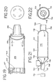
- FIGS. 19 and 20 Another embodiment of the aerosol medication delivery apparatus is shown in FIGS. 19 and 20.
- An aerosol delivery apparatus 610 includes a chamber housing 624 defining an interior space 639.
- the apparatus 610 also includes an elastomeric backpiece 627 which may be similar to the backpiece in the embodiment shown in FIGS. 17 and 18.
- the apparatus 610 includes a containment baffle 651.
- the containment baffle 651 is located at the downstream end of the chamber housing 624 just upstream of the mouthpiece 655.
- the containment baffle 651 includes an inhalation opening area 670 located around the periphery of the containment baffle 651.
- the containment baffle 651 may be formed of a single piece of material with the chamber housing 624.
- the mouthpiece 655 may be formed of a separate piece of material that is coupled to the downstream end of the chamber housing 624.
- the embodiment of FIGS. 19 and 20 may be used in a similar manner as the embodiment of FIGS. 17 and 18.
- FIGS. 21 and 22 Still another embodiment of the aerosol medication delivery apparatus is shown in FIGS. 21 and 22.
- This embodiment of the aerosol delivery apparatus is particularly suited for use by a mechanically ventilated patient (i.e. a patient using a ventilator).
- an aerosol delivery apparatus 710 includes components that are similar to the previous embodiments, in particular the embodiment of FIGS. 17 and 18.
- a chamber housing 724 defines an interior space 739.
- the apparatus 710 is intended to be positioned in a ventilator circuit, in particular in the air passageway that provides inspiratory air flow from a ventilator to the patient.
- the chamber housing 724 includes a first opening 727 located in a first tubular extension 728 extending from the upstream end 746 of the chamber housing 724 and a second opening 755 located in a second tubular extension 756 that extends from the downstream end 748 of the chamber housing 724.
- the first opening 727 connects to tubing 731 that leads to the ventilator (not shown) and the second opening 755 leads to tubing, a mask, a mouthpiece, or other suitable means (not shown) of providing air from the ventilator to the patient.
- Located at the upstream end of the chamber 724 is a receptacle 722.
- a well 734 adapted to receive the stem of a pMDI canister.
- the well 734 extends into a rib 735 that extends across the entrance into the interior space 739 of the chamber housing 724.
- the rib 735 may be located at or along the extension 728.
- the rib 735 includes a discharge opening 736 that communicates with the well 734.
- the discharge opening 736 is oriented toward the interior space 739.
- the receptacle 722, the rib 735, and the discharge opening 736 are integrated with the chamber housing 724 forming part of the aerosol delivery apparatus 710, (i.e. the receptacle and chamber housing form an integrated unit).
- the receptacle 722, the rib 735, and the discharge opening 736 are formed of the same piece of material as the chamber housing 724, or alternatively, they may be formed of separate pieces. Further disclosure regarding an integrated chamber housing and canister receptacle is included in U.S. Pat. No. 5,012,804.
- the containment baffle 751 may be located at the downstream end of the chamber housing 724 or along the extension 756.
- the containment baffle 751 includes an inhalation opening area 770 located around the periphery of the containment baffle 751.
- FIGS. 21 and 22 may be used in a similar manner as the device disclosed in U.S. Pat. No. 5,012.804.
- the apparatus 710 may be positioned in the inspiratory flow path from the ventilator to the patient when the patient is initially placed on the ventilator. The apparatus 710 is then left in place until needed. Alternatively, the apparatus 710 may be positioned in the inspiratory flow path of the ventilator circuit just prior to when a dose of aerosol medication is to be delivered to a ventilated patient.
- a pMDI canister is positioned in the receptacle 722 and actuated. The medication from the pMDI canister is conveyed with the inspiratory flow from the ventilator to the patient.
- the containment baffle 751 reduces on-axis non-respirable particles.
Description
Claims (21)
- An aerosol medication delivery apparatus (10, 110, 510, 610, 710) for use with a pMDI canister (30) having medication and a propellant contained therein under pressure, wherein the pMDI canister (30) has a discharge orifice from which the medication and propellant can be discharged forming an aerosol, the apparatus comprising a chamber housing (24, 124, 524, 624, 724) having an input end (46, 746) and an output end (48, 748) and defining an interior space (39, 539, 639, 739), wherein said input end (46, 746) receives the medication discharged from the discharge orifice of the pMDI canister (30) into said interior space (39, 539, 639, 739) and wherein the medication can be withdrawn from said interior space by inhalation by a patient from the output end (48, 748),
characterised by a concave-like or a convex-like shaped containment baffle (51, 151, 351, 451, 551, 651, 751) comprised by a solid centre portion (62, 362, 462, 565) located along a central axis (42) of said chamber housing (24, 124, 524, 624, 724), which is surrounded by an inhalation area (70, 470, 570, 670, 770) including at least one opening, said containment baffle (51, 151, 351, 451, 551, 651, 751) forming a distal wall (53) of said chamber housing (24, 124, 524, 624, 724) and being located at said output end (48, 748) to partially block said output end. - The aerosol delivery apparatus of claim 1 wherein said inhalation area (70, 470, 570, 670,. 770) is located concentrically with said solid centre portion (62, 362, 462, 562).
- The aerosol delivery apparatus of claim 1 or 2 where said containment baffle (51, 151, 251, 351, 451, 551, 651, 751) is aligned with said discharge orifice.
- The aerosol delivery apparatus of any one of claims 1 to 4 wherein said inhalation opening area (70, 470, 570, 670, 770) comprises four arcuate-shaped openings.
- The aerosol delivery apparatus of any one of claims 1 to 4 wherein said containment baffle (51, 151, 351, 451) has curved top and bottom sides (57C, 57D) and straight vertical sides (57A, 57B).
- The aerosol delivery apparatus of any one of claims 1 to 4 wherein said containment baffle (51, 151, 451, 551, 651, 751) includes a centre portion (62, 462, 562) coupled to said chamber housing (24, 124, 524, 624, 724) by a plurality of ribs.
- The aerosol delivery apparatus of claim 1 wherein said containment baffle (351) comprises a centre portion (362) having a plurality of openings formed through a periphery thereof.
- An aerosol medication delivery apparatus (10, 110, 510, 610, 710) for use with a pMDI canister (30) having medication and a propellant contained therein under pressure, wherein the pMDI canister (30) has a discharge orifice from which the medication and propellant can be discharged forming an aerosol, the apparatus comprising a chamber housing (24, 124, 524, 624, 724) having an input end (46,. 746) and an output end (48, 748) and defining an interior space (39, 539, 639, 739), wherein said input end (46, 746) receives the medication discharged from the discharge orifice of the pMDI canister (30) into said interior space (39, 539, 639, 739) and wherein the medication can be withdrawn from said interior space by inhalation by a patient from the output end (48, 748),
characterised by a concave-like or a convex-like shaped containment baffle (251) comprised by a screen-like mesh (252) defining a plurality of openings therethrough, said containment baffle (251) forming a distal wall (53) of said chamber housing (24, 124, 524, 624, 724) and being located at said output end (48, 748) to partially block said output end. - The aerosol delivery apparatus of any one of claims 1 to 8 wherein said containment baffle (151, 651, 751) is located at an upstream end of a mouthpiece (755) extending from said output end (748) of said chamber housing portion (124, 724).
- The aerosol delivery apparatus of any one of claims 1 to 8 wherein said containment baffle (51, 551) is located at a downstream end of a mouthpiece (55, 555) extending from said output end (48) of said chamber housing portion (24, 524).
- The aerosol delivery apparatus of any one of claims 1 to 10 where said chamber housing (124) has squared-off sides.
- The aerosol delivery apparatus of any one of claims 1 to 11 wherein said output end (48, 748) of said chamber housing (24, 124, 524, 724) is connected to said containment baffle (51, 551, 751) by a curved side wall portion reducing the cross-sectioned area from a first, greater area within said chamber housing (24, 124, 524, 724) to a second smaller area of said containment baffle (51, 551, 751)
- The aerosol delivery apparatus of any one of claims 1 to 12 wherein a backpiece (527, 627) is located on the input end of the chamber housing (524, 624), said backpiece including an opening (529, 629) located therein to receive a mouthpiece of an actuator boot of the pMDI canister.
- The aerosol delivery apparatus of any one of claims 1 to 12 wherein a receptacle (722) is coupled to the chamber housing (724) at an upstream portion thereof, and a well (734) is located in a bottom of said receptacle (722), said well (734) communicating with said discharge orifice; and said chamber housing portion (724) includes a first opening (727) at said input end (746) coupled to a ventilator circuit and a second opening (755) at said output end (748) leading to the patient.
- The aerosol delivery apparatus of claim 14 wherein said receptacle (722) and chamber housing (724) are formed of an integrated unit.
- The aerosol medication delivery apparatus according to any one of claims 1 to 12 comprising: a canister-holding portion (22) comprising a receptacle (28) for receipt therein of a pMDI canister (30), said canister-holding portion (22) having a discharge orifice communicating with said receptacle (28) to receive the medication and propellant from said pMDI canister (30); said discharge orifice of said canister-holding portion (22) communicates with said interior space (29) at said input end (46).
- The aerosol delivery apparatus of claim 16 wherein ambient air can pass into said interior space (39) when an pMDI canister (30) is located in said canister-holding portion (22).
- The aerosol delivery apparatus of claim 16 or 17 further comprising a mechanism (94) coupling said canister-holding portion (22) and said chamber housing (24) providing for said canister-holding portion (22) to be retracted into said chamber housing (24) for storage and to be extended out of said chamber housing (24) and pivoted into position for use in dispensing medication.
- An aerosol therapy system comprising:the aerosol delivery apparatus of any one of claims 16 to 18; anda pMDI canister (30) of medication having a stem (32), wherein said canister (30) is located at least in part within said receptacle (28).
- The aerosol delivery system of claim 19 wherein said canister contains HFA.
- The aerosol delivery system of claim 19 wherein said medication includes flunisolide.
Applications Claiming Priority (3)
| Application Number | Priority Date | Filing Date | Title |
|---|---|---|---|
| US08/938,686 US6345617B1 (en) | 1997-09-26 | 1997-09-26 | Aerosol medication delivery apparatus and system |
| US938686 | 1997-09-26 | ||
| PCT/IB1998/001681 WO1999016490A1 (en) | 1997-09-26 | 1998-09-16 | Aerosol medication delivery apparatus and system |
Publications (2)
| Publication Number | Publication Date |
|---|---|
| EP1019127A1 EP1019127A1 (en) | 2000-07-19 |
| EP1019127B1 true EP1019127B1 (en) | 2003-11-05 |
Family
ID=25471799
Family Applications (1)
| Application Number | Title | Priority Date | Filing Date |
|---|---|---|---|
| EP98946684A Expired - Lifetime EP1019127B1 (en) | 1997-09-26 | 1998-09-16 | Aerosol medication delivery apparatus |
Country Status (9)
| Country | Link |
|---|---|
| US (1) | US6345617B1 (en) |
| EP (1) | EP1019127B1 (en) |
| JP (2) | JP2001518323A (en) |
| AR (1) | AR013968A1 (en) |
| AU (1) | AU739002B2 (en) |
| CA (3) | CA2304498C (en) |
| DE (1) | DE69819541T2 (en) |
| WO (1) | WO1999016490A1 (en) |
| ZA (1) | ZA988203B (en) |
Families Citing this family (68)
| Publication number | Priority date | Publication date | Assignee | Title |
|---|---|---|---|---|
| US5823179A (en) * | 1996-02-13 | 1998-10-20 | 1263152 Ontario Inc. | Nebulizer apparatus and method |
| US6345617B1 (en) | 1997-09-26 | 2002-02-12 | 1263152 Ontario Inc. | Aerosol medication delivery apparatus and system |
| US6293279B1 (en) | 1997-09-26 | 2001-09-25 | Trudell Medical International | Aerosol medication delivery apparatus and system |
| US20060213505A1 (en) * | 1997-11-14 | 2006-09-28 | Astrazeneca Ab | Inhalation device |
| US7967011B2 (en) * | 1997-11-14 | 2011-06-28 | Astrazeneca Ab | Inhalation device |
| SE9704185D0 (en) * | 1997-11-14 | 1997-11-14 | Astra Pharma Prod | Inhalation device |
| US6397837B1 (en) * | 1999-07-22 | 2002-06-04 | Martin W. Ferris | Inhaler assistive device |
| GB2360219A (en) | 2000-03-18 | 2001-09-19 | Astrazeneca Uk Ltd | Inhaler |
| CA2826724C (en) | 2000-04-11 | 2016-02-02 | Trudell Medical International | Aerosol delivery apparatus with positive expiratory pressure capacity |
| US6501052B2 (en) * | 2000-12-22 | 2002-12-31 | Chrysalis Technologies Incorporated | Aerosol generator having multiple heating zones and methods of use thereof |
| US6698422B2 (en) * | 2001-03-12 | 2004-03-02 | Birdsong Medical Devices, Inc. | Canister inhaler having a spacer and easy to operate lever mechanism and a flexible, elastic mouthpiece |
| CA2809180C (en) | 2001-03-20 | 2015-06-02 | Trudell Medical International | Nebulizer apparatus with an adjustable fluid orifice |
| CA2452140C (en) * | 2001-06-26 | 2010-12-14 | Norton Healthcare, Ltd. | An improved aerosol actuator |
| US8440791B2 (en) * | 2001-09-06 | 2013-05-14 | Mgp Biotechnologies, Llc | Thimerosal removal device |
| US7767872B2 (en) * | 2001-09-06 | 2010-08-03 | Mpg Biotechnologies, Llc | Thimerosal removal device |
| US20030205226A1 (en) * | 2002-05-02 | 2003-11-06 | Pre Holding, Inc. | Aerosol medication inhalation system |
| AU2003225071A1 (en) * | 2002-05-03 | 2003-11-17 | Trudell Medical International | Aerosol medication delivery apparatus with narrow orifice |
| US6904908B2 (en) | 2002-05-21 | 2005-06-14 | Trudell Medical International | Visual indicator for an aerosol medication delivery apparatus and system |
| US7360537B2 (en) * | 2003-04-16 | 2008-04-22 | Trudell Medical International | Antistatic medication delivery apparatus |
| US8235036B2 (en) * | 2005-09-09 | 2012-08-07 | Vedat Obuz | Portable universal inhaler system |
| US20070074718A1 (en) * | 2005-10-04 | 2007-04-05 | Sp Medical Llc | Metered dose inhaler having spacing device |
| US20090250058A1 (en) * | 2006-07-14 | 2009-10-08 | Astrazeneca Ab | Inhalation System and Delivery Device for the Administration of a Drug in the Form of Dry Powder |
| CA2661152A1 (en) * | 2006-08-21 | 2008-02-28 | Trudell Medical International | Respiratory muscle endurance training device and method for the use thereof |
| AU2008331443B2 (en) * | 2007-12-08 | 2010-11-04 | Efthimiou, Dimitrios Mr | Personal air filter with amplifier and vibrator |
| EP2338575B1 (en) | 2008-02-21 | 2017-05-31 | Trudell Medical International | Respiratory muscle endurance training device and method for the use thereof |
| US8251876B2 (en) * | 2008-04-22 | 2012-08-28 | Hill-Rom Services, Inc. | Breathing exercise apparatus |
| US8539951B1 (en) | 2008-05-27 | 2013-09-24 | Trudell Medical International | Oscillating positive respiratory pressure device |
| US8327849B2 (en) | 2008-10-28 | 2012-12-11 | Trudell Medical International | Oscillating positive expiratory pressure device |
| US9149589B2 (en) | 2009-02-23 | 2015-10-06 | Trudell Medical International | Method and device for performing orientation dependent oscillating positive expiratory pressure therapy |
| US8485179B1 (en) | 2009-02-23 | 2013-07-16 | Trudell Medical International | Oscillating positive expiratory pressure device |
| JP5919277B2 (en) * | 2010-09-21 | 2016-05-18 | コーニンクレッカ フィリップス エヌ ヴェKoninklijke Philips N.V. | Holding chamber with valve including valve holding system |
| MX343608B (en) | 2010-11-30 | 2016-11-14 | Teva Pharma | Inhalers and housing caps for inhalers. |
| RU2615280C2 (en) | 2011-06-06 | 2017-04-04 | Труделл Медикал Интернешнл | Device with oscillatory positive pressure at exhalation |
| US8695589B2 (en) | 2011-12-06 | 2014-04-15 | Anthony J. Mullane | Inhaler assist device |
| US9180271B2 (en) | 2012-03-05 | 2015-11-10 | Hill-Rom Services Pte. Ltd. | Respiratory therapy device having standard and oscillatory PEP with nebulizer |
| US9364622B2 (en) | 2012-04-20 | 2016-06-14 | Fsc Laboratories, Inc. | Inhalation devices and systems and methods including the same |
| US9517315B2 (en) | 2012-11-30 | 2016-12-13 | Trudell Medical International | Oscillating positive expiratory pressure device |
| CA156938S (en) | 2013-02-14 | 2014-07-08 | Clement Clarke Int Ltd | Spacer for an asthma inhaler |
| USD735316S1 (en) | 2013-03-11 | 2015-07-28 | Fsc Laboratories, Inc. | Inhalation spacer |
| CA2915949C (en) | 2013-07-12 | 2020-01-28 | Trudell Medical International | Huff cough simulation device |
| US10207065B2 (en) | 2013-07-12 | 2019-02-19 | John H. Silva | Mouthpiece for inhalers |
| US9849257B2 (en) | 2013-08-22 | 2017-12-26 | Trudell Medical International | Oscillating positive respiratory pressure device |
| WO2015053361A1 (en) * | 2013-10-11 | 2015-04-16 | 株式会社リーチハイアー | Inhalation aid for oral powder |
| US10363383B2 (en) | 2014-02-07 | 2019-07-30 | Trudell Medical International | Pressure indicator for an oscillating positive expiratory pressure device |
| GB201408561D0 (en) * | 2014-05-14 | 2014-06-25 | The Technology Partnership Plc | Aerosolisation engine for liquid drug delivery |
| USD748242S1 (en) * | 2014-07-11 | 2016-01-26 | H. Stuart Campbell | Inhaler mouthpiece |
| US10004872B1 (en) | 2015-03-06 | 2018-06-26 | D R Burton Healthcare, Llc | Positive expiratory pressure device having an oscillating valve |
| CN205924624U (en) * | 2015-05-12 | 2017-02-08 | 深圳瑞之谷医疗科技有限公司 | Medicine glass subassembly and medical vaporizer |
| MX2018001321A (en) | 2015-07-30 | 2018-08-15 | Trudell Medical Int | Combined respiratory muscle training and oscillating positive expiratory pressure device. |
| USD780906S1 (en) | 2015-09-02 | 2017-03-07 | Trudell Medical International | Respiratory treatment device |
| USD778429S1 (en) | 2015-09-02 | 2017-02-07 | Trudell Medical International | Respiratory treatment device |
| US10857317B2 (en) | 2015-12-04 | 2020-12-08 | Trudell Medical International | Huff cough simulation device |
| US10850050B2 (en) | 2016-05-19 | 2020-12-01 | Trudell Medical International | Smart valved holding chamber |
| US10537693B2 (en) | 2016-05-30 | 2020-01-21 | Medical Developments International Limited | Collapsible disposable spacer for metered dose inhalers |
| WO2018007997A1 (en) | 2016-07-08 | 2018-01-11 | Trudell Medical International | Smart oscillating positive expiratory pressure device |
| US10786638B2 (en) | 2016-07-08 | 2020-09-29 | Trudell Medical International | Nebulizer apparatus and method |
| US11426539B2 (en) * | 2016-12-06 | 2022-08-30 | Heath Rainbow | Inhaler housing |
| ES2920151T3 (en) | 2016-12-09 | 2022-08-01 | Trudell Medical Int | smart nebulizer |
| EP3618908A4 (en) | 2017-05-03 | 2021-01-13 | Trudell Medical International | Combined oscillating positive expiratory pressure therapy and huff cough simulation device |
| DE102017219364B4 (en) | 2017-10-27 | 2022-07-07 | Weiss Klimatechnik Gmbh | Air conditioner and method for disinfecting an air conditioner |
| MX2020007026A (en) | 2018-01-04 | 2020-12-03 | Trudell Medical Int | Smart oscillating positive expiratory pressure device. |
| US10953278B2 (en) | 2018-02-02 | 2021-03-23 | Trudell Medical International | Oscillating positive expiratory pressure device |
| WO2019236662A1 (en) | 2018-06-05 | 2019-12-12 | Teleflex Medical Incorporated | Valved spacer for inhalation device |
| CA3119536A1 (en) * | 2018-11-14 | 2020-05-22 | Loop Laboratories, LLC | Inhalant dispensing system and apparatus |
| WO2020243024A1 (en) * | 2019-05-24 | 2020-12-03 | Blue Ocean Group, LLC | Compact spacer for metered dose inhaler |
| GB201909172D0 (en) * | 2019-06-26 | 2019-08-07 | Royal College Of Art | Inhaler |
| EP4021542A4 (en) | 2019-08-27 | 2023-09-06 | Trudell Medical International | Smart oscillating positive expiratory pressure device |
| USD1010101S1 (en) | 2020-09-18 | 2024-01-02 | Trudell Medical International | Holding chamber |
Citations (1)
| Publication number | Priority date | Publication date | Assignee | Title |
|---|---|---|---|---|
| US3236458A (en) * | 1962-02-23 | 1966-02-22 | Ramis Jean | Aerosol apparatus |
Family Cites Families (67)
| Publication number | Priority date | Publication date | Assignee | Title |
|---|---|---|---|---|
| US2670739A (en) | 1951-07-02 | 1954-03-02 | Charles M Mcneill | Inhaler |
| GB975754A (en) | 1961-05-15 | 1964-11-18 | Pfizer Ltd | Medicament administering apparatus |
| GB1017032A (en) | 1963-12-12 | 1966-01-12 | Aerosmoke Ltd | Aerosol compositions |
| DE1972590U (en) | 1964-06-15 | 1967-11-16 | Asmund S Laerdal | VALVE FOR REVIVAL APPARATUS. |
| US3565071A (en) | 1968-09-19 | 1971-02-23 | Abbott Lab | Self-regulating therapeutic inhaler |
| US3809084A (en) | 1970-02-16 | 1974-05-07 | American Cyanamid Co | Pressurized portable dispenser |
| US3643686A (en) | 1970-10-21 | 1972-02-22 | Ewald Koegel | High-velocity breathing valve |
| US3838686A (en) | 1971-10-14 | 1974-10-01 | G Szekely | Aerosol apparatus for inhalation therapy |
| US3897779A (en) | 1973-06-27 | 1975-08-05 | American Cyanamid Co | Triamcinolone acetonide inhalation therapy |
| US3809294A (en) | 1973-06-27 | 1974-05-07 | American Cyanamid Co | Dispensing lung contacting powdered medicaments |
| US3994421A (en) | 1975-09-29 | 1976-11-30 | American Cyanamid Company | Unitary therapeutic aerosol dispenser |
| SE411705B (en) | 1976-11-09 | 1980-02-04 | Draco Ab | DEVICE FOR GENERATION OF A SHIELD, ESSENTIAL FUEL-FREE AEROSOL |
| GB2000555A (en) | 1977-07-01 | 1979-01-10 | Ici Ltd | Aerosol dispensing device |
| GR69682B (en) | 1978-09-11 | 1982-07-08 | Newhouse Michael T | |
| SE415957B (en) | 1979-02-16 | 1980-11-17 | Draco Ab | Aerosol inhalation device |
| SE433443B (en) * | 1981-09-15 | 1984-05-28 | Draco Ab | Aerosol inhalation device |
| US4509515A (en) * | 1982-02-23 | 1985-04-09 | Fisons Plc | Inhalation device |
| US4470412A (en) | 1982-03-19 | 1984-09-11 | Trutek Research, Inc. | Inhalation valve |
| ATE27405T1 (en) | 1983-08-02 | 1987-06-15 | Trutek Research Inc | RESPIRATORY VALVE. |
| FI69962C (en) | 1983-12-28 | 1986-09-12 | Huhtamaeki Oy | INHALATIONSANORDNING |
| US4637528A (en) | 1984-01-19 | 1987-01-20 | William H. Rorer, Inc. | Articulated joint in aerosol medicament dispenser |
| SE453566B (en) * | 1986-03-07 | 1988-02-15 | Draco Ab | POWDER INHALATOR DEVICE |
| FI89458C (en) | 1986-11-06 | 1993-10-11 | Leiras Oy | INHALERINGSANORDNING |
| JPS63143081A (en) | 1986-12-05 | 1988-06-15 | メクト株式会社 | Inhalator |
| US4796614A (en) * | 1987-02-26 | 1989-01-10 | Trutek Research, Inc. | Collapsible inhalation valve |
| JPH0199570A (en) * | 1987-09-30 | 1989-04-18 | Bootran Medical Technol Inc | Method and apparutus for inhalation |
| IT1217890B (en) | 1988-06-22 | 1990-03-30 | Chiesi Farma Spa | DOSED AEROSOL INHALATION DEVICE |
| US4852561A (en) * | 1988-07-27 | 1989-08-01 | Sperry C R | Inhalation device |
| US5012804A (en) | 1989-03-06 | 1991-05-07 | Trudell Medical | Medication inhaler with adult mask |
| US5012803A (en) * | 1989-03-06 | 1991-05-07 | Trudell Medical | Modular medication inhaler |
| GB8908647D0 (en) | 1989-04-17 | 1989-06-01 | Glaxo Group Ltd | Device |
| GB8915420D0 (en) | 1989-07-05 | 1989-08-23 | Fisons Plc | Inhalation device |
| GB8917775D0 (en) * | 1989-08-03 | 1989-09-20 | Atomic Energy Authority Uk | Aerosol inhaler |
| IT1237118B (en) * | 1989-10-27 | 1993-05-18 | Miat Spa | MULTI-DOSE INHALER FOR POWDER DRUGS. |
| US5042467A (en) | 1990-03-28 | 1991-08-27 | Trudell Medical | Medication inhaler with fitting having a sonic signalling device |
| US5178138A (en) * | 1990-09-11 | 1993-01-12 | Walstrom Dennis R | Drug delivery device |
| RU2095092C1 (en) | 1990-09-12 | 1997-11-10 | Бисгорд Ханс | Device for inhalation of active powder-like or liquid substance |
| IT1244441B (en) | 1990-09-13 | 1994-07-15 | Chiesi Farma Spa | MOUTH INHALATION DEVICE FOR AEROSOL DRUGS |
| GB9021433D0 (en) * | 1990-10-02 | 1990-11-14 | Atomic Energy Authority Uk | Power inhaler |
| US5040527A (en) | 1990-12-18 | 1991-08-20 | Healthscan Products Inc. | Metered dose inhalation unit with slide means |
| AU651882B2 (en) * | 1991-05-14 | 1994-08-04 | Visiomed Group Limited | Aerosol inhalation device |
| DK0585379T3 (en) | 1991-05-21 | 1999-06-21 | Abbott Lab | The aerosol inhalation device |
| US5241954A (en) | 1991-05-24 | 1993-09-07 | Glenn Joseph G | Nebulizer |
| IT1248059B (en) | 1991-06-14 | 1995-01-05 | Miat Spa | MULTI-DOSE INSUFFLATOR FOR POWDER DRUGS |
| AU662919B2 (en) | 1991-07-02 | 1995-09-21 | Inhale, Inc. | Method and device for delivering aerosolized medicaments |
| US6123075A (en) | 1991-10-15 | 2000-09-26 | Mallinckrodt, Inc. | Resuscitator regulator with carbon dioxide detector |
| DE4208880A1 (en) * | 1992-03-19 | 1993-09-23 | Boehringer Ingelheim Kg | SEPARATOR FOR POWDER INHALATORS |
| US5297543A (en) | 1992-06-24 | 1994-03-29 | Healthscan Products, Inc. | Medication inhaler mixer |
| US6582728B1 (en) | 1992-07-08 | 2003-06-24 | Inhale Therapeutic Systems, Inc. | Spray drying of macromolecules to produce inhaleable dry powders |
| FI95873C (en) * | 1992-10-15 | 1996-04-10 | Orion Yhtymae Oy | Valve for use with an inhaler |
| US5505194A (en) | 1994-03-23 | 1996-04-09 | Abbott Laboratories | Aerosol inhalation device having slideably and rotatably connected elliptical cylinder portions |
| SE9401220D0 (en) | 1994-04-11 | 1994-04-11 | Astra Ab | Valve |
| CA2124410A1 (en) * | 1994-05-26 | 1995-11-27 | Jean-Paul Praud | Device for the simultaneous delivery of beta 2 agonists and oxygen to a patient |
| US5477849A (en) | 1994-05-31 | 1995-12-26 | Fry; Stephen | Spacer for medication inhaler |
| GB2299512A (en) | 1995-04-06 | 1996-10-09 | Ian James Sharp | Inhaler |
| PL182198B1 (en) | 1995-06-21 | 2001-11-30 | Asta Medica Ag | Pharmaceutic powder holding container with integrated measuring device and powdered |
| GB9513218D0 (en) | 1995-06-29 | 1995-09-06 | Fisons Plc | Inhalation device and method |
| AUPN417395A0 (en) | 1995-07-14 | 1995-08-10 | Techbase Pty. Ltd. | An improved spacer |
| US5617844A (en) | 1995-09-21 | 1997-04-08 | King; Russell W. | Aerosol medication delivery system |
| US5738087A (en) | 1995-09-21 | 1998-04-14 | King; Russell W. | Aerosol medication delivery system |
| GB2310607A (en) | 1996-02-29 | 1997-09-03 | Norton Healthcare Ltd | Spacer device for inhalers |
| FR2751553B1 (en) | 1996-07-23 | 1999-06-11 | Pedrali Franck | PROCESS FOR IMPROVING THE DIFFUSION OF A SPRAY BRONCHODILATOR AND APPARATUSES USING THE SAME |
| US5765553A (en) | 1996-11-27 | 1998-06-16 | Diemolding Corporation | Aerosol medication delivery facemask adapter |
| GB9626263D0 (en) | 1996-12-18 | 1997-02-05 | Innovata Biomed Ltd | Powder inhaler |
| US6345617B1 (en) | 1997-09-26 | 2002-02-12 | 1263152 Ontario Inc. | Aerosol medication delivery apparatus and system |
| US6039042A (en) | 1998-02-23 | 2000-03-21 | Thayer Medical Corporation | Portable chamber for metered dose inhaler dispensers |
| US6026807A (en) | 1998-02-27 | 2000-02-22 | Diemolding Corporation | Metered dose inhaler cloud chamber |
-
1997
- 1997-09-26 US US08/938,686 patent/US6345617B1/en not_active Expired - Lifetime
-
1998
- 1998-09-08 ZA ZA9808203A patent/ZA988203B/en unknown
- 1998-09-16 CA CA002304498A patent/CA2304498C/en not_active Expired - Lifetime
- 1998-09-16 EP EP98946684A patent/EP1019127B1/en not_active Expired - Lifetime
- 1998-09-16 JP JP2000513619A patent/JP2001518323A/en active Pending
- 1998-09-16 AU AU93644/98A patent/AU739002B2/en not_active Expired
- 1998-09-16 DE DE69819541T patent/DE69819541T2/en not_active Expired - Lifetime
- 1998-09-16 CA CA2790025A patent/CA2790025A1/en not_active Abandoned
- 1998-09-16 WO PCT/IB1998/001681 patent/WO1999016490A1/en active IP Right Grant
- 1998-09-16 CA CA2689736A patent/CA2689736C/en not_active Expired - Lifetime
- 1998-09-25 AR ARP980104800A patent/AR013968A1/en unknown
-
2009
- 2009-10-09 JP JP2009235307A patent/JP5137929B2/en not_active Expired - Lifetime
Patent Citations (1)
| Publication number | Priority date | Publication date | Assignee | Title |
|---|---|---|---|---|
| US3236458A (en) * | 1962-02-23 | 1966-02-22 | Ramis Jean | Aerosol apparatus |
Also Published As
| Publication number | Publication date |
|---|---|
| CA2304498C (en) | 2010-01-05 |
| DE69819541D1 (en) | 2003-12-11 |
| EP1019127A1 (en) | 2000-07-19 |
| ZA988203B (en) | 2000-03-22 |
| CA2790025A1 (en) | 1999-04-08 |
| CA2689736C (en) | 2012-12-18 |
| AU739002B2 (en) | 2001-10-04 |
| CA2689736A1 (en) | 1999-04-08 |
| JP2010046500A (en) | 2010-03-04 |
| JP2001518323A (en) | 2001-10-16 |
| WO1999016490A1 (en) | 1999-04-08 |
| DE69819541T2 (en) | 2004-04-15 |
| US6345617B1 (en) | 2002-02-12 |
| JP5137929B2 (en) | 2013-02-06 |
| CA2304498A1 (en) | 1999-04-08 |
| AR013968A1 (en) | 2001-01-31 |
| AU9364498A (en) | 1999-04-23 |
Similar Documents
| Publication | Publication Date | Title |
|---|---|---|
| EP1019127B1 (en) | Aerosol medication delivery apparatus | |
| US6293279B1 (en) | Aerosol medication delivery apparatus and system | |
| AU777562B2 (en) | Internal vortex mechanism for inhaler device | |
| US5699789A (en) | Dry powder inhaler | |
| JP5395100B2 (en) | Method and apparatus for delivering aerosolized drug | |
| JPH0623048A (en) | Apparatus for oral inhalation of aerosol drug | |
| US20160067429A1 (en) | Methods and apparatus for delivering aerosolized medication | |
| EP0774986B1 (en) | Inhaler apparatus with optimisation chamber | |
| MXPA00002949A (en) | Aerosol medication delivery apparatus and system |
Legal Events
| Date | Code | Title | Description |
|---|---|---|---|
| PUAI | Public reference made under article 153(3) epc to a published international application that has entered the european phase |
Free format text: ORIGINAL CODE: 0009012 |
|
| 17P | Request for examination filed |
Effective date: 20000329 |
|
| AK | Designated contracting states |
Kind code of ref document: A1 Designated state(s): DE ES FR GB IE IT |
|
| GRAH | Despatch of communication of intention to grant a patent |
Free format text: ORIGINAL CODE: EPIDOS IGRA |
|
| RTI1 | Title (correction) |
Free format text: AEROSOL MEDICATION DELIVERY APPARATUS |
|
| GRAS | Grant fee paid |
Free format text: ORIGINAL CODE: EPIDOSNIGR3 |
|
| GRAA | (expected) grant |
Free format text: ORIGINAL CODE: 0009210 |
|
| AK | Designated contracting states |
Kind code of ref document: B1 Designated state(s): DE ES FR GB IE IT |
|
| PG25 | Lapsed in a contracting state [announced via postgrant information from national office to epo] |
Ref country code: IT Free format text: LAPSE BECAUSE OF FAILURE TO SUBMIT A TRANSLATION OF THE DESCRIPTION OR TO PAY THE FEE WITHIN THE PRESCRIBED TIME-LIMIT;WARNING: LAPSES OF ITALIAN PATENTS WITH EFFECTIVE DATE BEFORE 2007 MAY HAVE OCCURRED AT ANY TIME BEFORE 2007. THE CORRECT EFFECTIVE DATE MAY BE DIFFERENT FROM THE ONE RECORDED. Effective date: 20031105 Ref country code: FR Free format text: LAPSE BECAUSE OF FAILURE TO SUBMIT A TRANSLATION OF THE DESCRIPTION OR TO PAY THE FEE WITHIN THE PRESCRIBED TIME-LIMIT Effective date: 20031105 |
|
| REG | Reference to a national code |
Ref country code: GB Ref legal event code: FG4D |
|
| REF | Corresponds to: |
Ref document number: 69819541 Country of ref document: DE Date of ref document: 20031211 Kind code of ref document: P |
|
| REG | Reference to a national code |
Ref country code: IE Ref legal event code: FG4D |
|
| PG25 | Lapsed in a contracting state [announced via postgrant information from national office to epo] |
Ref country code: ES Free format text: LAPSE BECAUSE OF FAILURE TO SUBMIT A TRANSLATION OF THE DESCRIPTION OR TO PAY THE FEE WITHIN THE PRESCRIBED TIME-LIMIT Effective date: 20040216 |
|
| PLBE | No opposition filed within time limit |
Free format text: ORIGINAL CODE: 0009261 |
|
| STAA | Information on the status of an ep patent application or granted ep patent |
Free format text: STATUS: NO OPPOSITION FILED WITHIN TIME LIMIT |
|
| PG25 | Lapsed in a contracting state [announced via postgrant information from national office to epo] |
Ref country code: IE Free format text: LAPSE BECAUSE OF NON-PAYMENT OF DUE FEES Effective date: 20040916 |
|
| 26N | No opposition filed |
Effective date: 20040806 |
|
| EN | Fr: translation not filed | ||
| REG | Reference to a national code |
Ref country code: IE Ref legal event code: MM4A |
|
| REG | Reference to a national code |
Ref country code: GB Ref legal event code: 732E |
|
| PGFP | Annual fee paid to national office [announced via postgrant information from national office to epo] |
Ref country code: GB Payment date: 20170921 Year of fee payment: 20 Ref country code: DE Payment date: 20170927 Year of fee payment: 20 |
|
| REG | Reference to a national code |
Ref country code: DE Ref legal event code: R071 Ref document number: 69819541 Country of ref document: DE |
|
| REG | Reference to a national code |
Ref country code: GB Ref legal event code: PE20 Expiry date: 20180915 |
|
| PG25 | Lapsed in a contracting state [announced via postgrant information from national office to epo] |
Ref country code: GB Free format text: LAPSE BECAUSE OF EXPIRATION OF PROTECTION Effective date: 20180915 |