EP1018726A2 - Method and apparatus for reconstructing a linear prediction filter excitation signal - Google Patents
Method and apparatus for reconstructing a linear prediction filter excitation signal Download PDFInfo
- Publication number
- EP1018726A2 EP1018726A2 EP00100065A EP00100065A EP1018726A2 EP 1018726 A2 EP1018726 A2 EP 1018726A2 EP 00100065 A EP00100065 A EP 00100065A EP 00100065 A EP00100065 A EP 00100065A EP 1018726 A2 EP1018726 A2 EP 1018726A2
- Authority
- EP
- European Patent Office
- Prior art keywords
- signal
- linear prediction
- excitation
- reconstructing
- spectrum
- Prior art date
- Legal status (The legal status is an assumption and is not a legal conclusion. Google has not performed a legal analysis and makes no representation as to the accuracy of the status listed.)
- Granted
Links
Images


Classifications
-
- G—PHYSICS
- G10—MUSICAL INSTRUMENTS; ACOUSTICS
- G10L—SPEECH ANALYSIS TECHNIQUES OR SPEECH SYNTHESIS; SPEECH RECOGNITION; SPEECH OR VOICE PROCESSING TECHNIQUES; SPEECH OR AUDIO CODING OR DECODING
- G10L19/00—Speech or audio signals analysis-synthesis techniques for redundancy reduction, e.g. in vocoders; Coding or decoding of speech or audio signals, using source filter models or psychoacoustic analysis
- G10L19/04—Speech or audio signals analysis-synthesis techniques for redundancy reduction, e.g. in vocoders; Coding or decoding of speech or audio signals, using source filter models or psychoacoustic analysis using predictive techniques
- G10L19/08—Determination or coding of the excitation function; Determination or coding of the long-term prediction parameters
Definitions
- This invention relates to a method and apparatus for reconstructing a linear prediction filter excitation signal.
- Such signal reconstruction is commonly employed in speech coding algorithms where a speech signal is decomposed to a spectral envelope and a residual signal for efficient transmission.
- phase information may be derived from the encoded magnitude spectrum using Sinusoidal Transform Coding
- synthetic and "buzzing" qualities still exist in the decoded speech owing to minimum phase assumptions in the speech production model.
- Improved speech quality has been reported when the phase spectra of some pre-stored waveforms are used, but only a little information from the pre-stored waveforms is revealed using this technique.
- an apparatus for reconstructing a linear prediction filter excitation signal as claimed in claim 1.
- a simple voiced speech production model is typically expressed in terms of three cascaded filters excited by a pseudo-periodic series of discrete time impulses e(n) , as illustrated in FIG. 1. These filters are:
- V(z) is used to model the K vocal tract resonances (or formants) which is assumed to be an all-pole model and has a transfer function: where values of ⁇ ' are the poles of V(z) .
- the frequency and bandwidth of a tormant is directly related to the location of the pole within the unit circle as shown in FIG. 2.
- L(z) is used to model the lip-radiation and is considered to be a differentiator which has a single positive zero on the real axis.
- the system function of the simple voice speech production model can be expressed in the Z-plane as illustrated in FIG. 2a.
- FIG. 3 the schematic diagram of a linear predictive (LP) based speech coder is shown.
- LP analysis (30) is used to estimate the spectral envelope of a segment of speech signal, and thus to yield a set of filter coefficients a k .
- the set of a k 's is used in an LP analysis filter (32) to process the speech segment to yield an LP residual signal r(n) .
- the LP residual, together with the set of filter coefficients, are encoded (34, 36) and transmitted over the channel (38).
- the two signals â k and ê ( n ) are re-covered (40, 42).
- the residual signal ê ( n ) is used as an excitation to an LP synthesis filter (44), and hence to obtain the synthesized speech ⁇ S ( n ) .
- LP analysis The function of LP analysis is to estimate the spectral envelope of the speech segment. It can be seen from FIG. 2a that this is equivalent to estimating the location of the poles inside the unit circle. It is often assumed that the magnitude effect of one of the glottal excitation poles ⁇ 's is cancelled out with the lip-radiation zero ⁇ . Hence LP analysis only estimates the locations of ⁇ i 's and one of the ⁇ 's. By passing through the speech segment to an LP analysis filter A(z) , the magnitude spectrum of the speech segment is flattened. This is effectively the same as putting the zero's on the locations of the poles. As a result, the LP residual signal should have a flat magnitude spectrum and zero phase, as shown in FIG. 2b.
- the LP residual will have a system function as illustrated in FIG. 4b.
- E(z) is an unstable system, this is not relevant since we are only interested in the phase response of the filter.
- an LP excitation is regenerated or reconstructed at the decoder using a flat magnitude and a derived phase spectrum, as shown in FIG. 5.
- a magnitude deriver (50) and a phase deriver (52) are used to compute the required magnitude and phase spectra from received parameters.
- the derived magnitude and phase signals are applied to an LP synthesis filter (54) to generate the reconstructed speech signal.
- phase spectrum is computed as:
- the magnitude spectrum of the LP excitation signal may be derived using the same argument or simply using the original magnitude spectrum of the LP residual. It will be appreciated that computational simplicity and bit-rate efficiency is gained by using a flat magnitude spectrum.
- ⁇ 1 (8)
- the value of a can be varied in the range of, say, 0.9 to 1.
- ⁇ is a zero which lies on the real axis, and hence it contributes as a spectral tilt on the spectral envelope.
- a set of LP filter coefficients is available at the decoder and these filter coefficient characterize the spectral envelope of an LP synthesis filter H(z) .
- phase spectrum is calculated as:
- Equation (14) suggests that the vocal tract filter V ( ⁇ ) and the lip-radiation filter L ( ⁇ ) are now excited by a combined source, G ( ⁇ ) and N ( ⁇ ).
- the combined excitation signal is composed of a glottal excitation for the lower frequency band and a noisy siganl for the higher frequency band.
- the speech signal is recovered using the following equation, where the synthesized speech is produced by driving a combined LP excitation through an LP synthesis filter H ( ⁇ ).
- the combined excitation is generated using a magnitude spectrum together with a derived phase spectrum for lower frequency band and a random phase spectrum for higher frequency band.
- the separation frequency ⁇ s may be determined at the encoder via an "analysis-by-synthesis" approach. This manner of determining the value of ⁇ s is shown in FIG. 6.
- a magnitude spectrum (62), a derived phase spectrum (64) and a full-band random phase spectrum (66) are determined prior to the generation of the combined excitation.
- the three spectra are used to generate (68) a combined excitation signal ê ( n ) for a value of ⁇ s .
- the combined excitation signal is used to excite H(z) (70) to yield a synthesized speech signal ⁇ s ( n ).
- the synthesized speech is then compared (72) with the original s(n) using a similarity measure.
- the similarity measure is defined as the cross-correlation between the two speech signals C(s,s and). This process is carried out for a range of values of ⁇ s (74). The value of ⁇ s which yields the highest similarity measure will be encoded and sent to the decoder. At the decoder, an identical copy of the three spectra is available and the re-generation process is exactly the same as at the encoder.
- ⁇ s may alternatively be estimated by using an open-loop approach, as shown in FIG. 7.
- a deterministic signal is generated (80) at the encoder using a magnitude spectrum (76) and a derived phase spectrum (78).
- the deterministic signal is then passed through an LP synthesis filter (82) to yield a synthesized speech signal.
- the synthesized speech signal is compared (84) with the original using a similarity measure C(s,s and). The more the synthesised speech is like the original, the higher will be the value of ⁇ s , i.e. glottal excitation dominates, and vice versa.
- the value of ⁇ s is encoded at the encoder (86), quantised and sent over the channel.
- the computational complexity of the encoder can be reduced with only a minor degradation in the speech quality.
Landscapes
- Engineering & Computer Science (AREA)
- Computational Linguistics (AREA)
- Signal Processing (AREA)
- Health & Medical Sciences (AREA)
- Audiology, Speech & Language Pathology (AREA)
- Human Computer Interaction (AREA)
- Physics & Mathematics (AREA)
- Acoustics & Sound (AREA)
- Multimedia (AREA)
- Compression, Expansion, Code Conversion, And Decoders (AREA)
- Magnetic Resonance Imaging Apparatus (AREA)
Abstract
Description





Claims (7)
- An apparatus for reconstructing a linear prediction synthesis filter excitation signal, the apparatus comprising:means for receiving parameters representative of a signal's magnitude and phase spectrum, and for producing therefrom a deterministic signal comprising a magnitude spectrum (50) and a phase spectrum (52); andmeans for receiving the deterministic signal and a noise signal and for reconstructing therefrom the signal for excitation of a linear prediction synthesis filter.
- An apparatus as claimed in claim 1 wherein the magnitude spectrum is substantially flat.
- An apparatus as claimed in claim 1 wherein the phase spectrum is derived from substantially the formula:where
 ε(ω) represents the phase at frequency ω,α is a predetermined constant,γ represents a desired degree of spectral tilting, andβ is substantially equal to the mean average of α and γ.
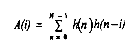
 - An apparatus as claimed in claim 3 wherein the value of γ is substantially equal to |-A(1)/A(0)|, where A(i) is the ith autocorrelation function of the impulse response of the linear prediction systhesis filter.
- An apparatus as claimed in claim 3 wherein the values of α, β and γ are substantially equal.
- An apparatus as claimed in claim 3 wherein the value of a is substantially equal to unity.
- A method of reconstructing a linear prediction synthesis filter excitation signal, the method comprising the steps of:receiving parameters representative of a signal's magnitude and phase spectrum, and producing therefrom a deterministic signal comprising a magnitude spectrum (50) and a phase spectrum (52);
andreceiving the deterministic signal and a noise signal and reconstructing therefrom the signal for excitation of a linear prediction synthesis filter.
Applications Claiming Priority (2)
| Application Number | Priority Date | Filing Date | Title |
|---|---|---|---|
| US226914 | 1999-01-05 | ||
| US09/226,914 US6304843B1 (en) | 1999-01-05 | 1999-01-05 | Method and apparatus for reconstructing a linear prediction filter excitation signal |
Publications (3)
| Publication Number | Publication Date |
|---|---|
| EP1018726A2 true EP1018726A2 (en) | 2000-07-12 |
| EP1018726A3 EP1018726A3 (en) | 2002-04-03 |
| EP1018726B1 EP1018726B1 (en) | 2005-10-26 |
Family
ID=22850961
Family Applications (1)
| Application Number | Title | Priority Date | Filing Date |
|---|---|---|---|
| EP00100065A Expired - Lifetime EP1018726B1 (en) | 1999-01-05 | 2000-01-05 | Method and apparatus for reconstructing a linear prediction filter excitation signal |
Country Status (4)
| Country | Link |
|---|---|
| US (1) | US6304843B1 (en) |
| EP (1) | EP1018726B1 (en) |
| AT (1) | ATE308099T1 (en) |
| DE (1) | DE60023366T2 (en) |
Families Citing this family (4)
| Publication number | Priority date | Publication date | Assignee | Title |
|---|---|---|---|---|
| US7065485B1 (en) * | 2002-01-09 | 2006-06-20 | At&T Corp | Enhancing speech intelligibility using variable-rate time-scale modification |
| US20090222268A1 (en) * | 2008-03-03 | 2009-09-03 | Qnx Software Systems (Wavemakers), Inc. | Speech synthesis system having artificial excitation signal |
| US10176835B1 (en) | 2018-06-22 | 2019-01-08 | Western Digital Technologies, Inc. | Data storage device employing predictive oversampling for servo control |
| CN113571079B (en) * | 2021-02-08 | 2025-07-11 | 腾讯科技(深圳)有限公司 | Speech enhancement method, device, equipment and storage medium |
Family Cites Families (11)
| Publication number | Priority date | Publication date | Assignee | Title |
|---|---|---|---|---|
| US5293448A (en) * | 1989-10-02 | 1994-03-08 | Nippon Telegraph And Telephone Corporation | Speech analysis-synthesis method and apparatus therefor |
| US5517595A (en) * | 1994-02-08 | 1996-05-14 | At&T Corp. | Decomposition in noise and periodic signal waveforms in waveform interpolation |
| US5754974A (en) * | 1995-02-22 | 1998-05-19 | Digital Voice Systems, Inc | Spectral magnitude representation for multi-band excitation speech coders |
| US5701390A (en) * | 1995-02-22 | 1997-12-23 | Digital Voice Systems, Inc. | Synthesis of MBE-based coded speech using regenerated phase information |
| FR2734389B1 (en) * | 1995-05-17 | 1997-07-18 | Proust Stephane | METHOD FOR ADAPTING THE NOISE MASKING LEVEL IN A SYNTHESIS-ANALYZED SPEECH ENCODER USING A SHORT-TERM PERCEPTUAL WEIGHTING FILTER |
| IT1277194B1 (en) * | 1995-06-28 | 1997-11-05 | Alcatel Italia | METHOD AND RELATED APPARATUS FOR THE CODING AND DECODING OF A CHAMPIONSHIP VOICE SIGNAL |
| US5774837A (en) * | 1995-09-13 | 1998-06-30 | Voxware, Inc. | Speech coding system and method using voicing probability determination |
| US6041297A (en) * | 1997-03-10 | 2000-03-21 | At&T Corp | Vocoder for coding speech by using a correlation between spectral magnitudes and candidate excitations |
| US6070137A (en) * | 1998-01-07 | 2000-05-30 | Ericsson Inc. | Integrated frequency-domain voice coding using an adaptive spectral enhancement filter |
| US6067511A (en) * | 1998-07-13 | 2000-05-23 | Lockheed Martin Corp. | LPC speech synthesis using harmonic excitation generator with phase modulator for voiced speech |
| US6119082A (en) * | 1998-07-13 | 2000-09-12 | Lockheed Martin Corporation | Speech coding system and method including harmonic generator having an adaptive phase off-setter |
-
1999
- 1999-01-05 US US09/226,914 patent/US6304843B1/en not_active Expired - Lifetime
-
2000
- 2000-01-05 AT AT00100065T patent/ATE308099T1/en not_active IP Right Cessation
- 2000-01-05 DE DE60023366T patent/DE60023366T2/en not_active Expired - Fee Related
- 2000-01-05 EP EP00100065A patent/EP1018726B1/en not_active Expired - Lifetime
Also Published As
| Publication number | Publication date |
|---|---|
| EP1018726A3 (en) | 2002-04-03 |
| ATE308099T1 (en) | 2005-11-15 |
| US6304843B1 (en) | 2001-10-16 |
| DE60023366D1 (en) | 2005-12-01 |
| EP1018726B1 (en) | 2005-10-26 |
| DE60023366T2 (en) | 2006-04-20 |
Similar Documents
| Publication | Publication Date | Title |
|---|---|---|
| JP4842538B2 (en) | Synthetic speech frequency selective pitch enhancement method and device | |
| JP4662673B2 (en) | Gain smoothing in wideband speech and audio signal decoders. | |
| EP0409239B1 (en) | Speech coding/decoding method | |
| EP1125286B1 (en) | Perceptual weighting device and method for efficient coding of wideband signals | |
| EP1141946B1 (en) | Coded enhancement feature for improved performance in coding communication signals | |
| CA2412449C (en) | Improved speech model and analysis, synthesis, and quantization methods | |
| US9037456B2 (en) | Method and apparatus for audio coding and decoding | |
| KR100304682B1 (en) | Fast Excitation Coding for Speech Coders | |
| EP0878790A1 (en) | Voice coding system and method | |
| KR20010102004A (en) | Celp transcoding | |
| US6052659A (en) | Nonlinear filter for noise suppression in linear prediction speech processing devices | |
| US5884251A (en) | Voice coding and decoding method and device therefor | |
| US5675701A (en) | Speech coding parameter smoothing method | |
| US5570453A (en) | Method for generating a spectral noise weighting filter for use in a speech coder | |
| US20040138886A1 (en) | Method and system for parametric characterization of transient audio signals | |
| EP1018726B1 (en) | Method and apparatus for reconstructing a linear prediction filter excitation signal | |
| US6801887B1 (en) | Speech coding exploiting the power ratio of different speech signal components | |
| EP0361432B1 (en) | Method of and device for speech signal coding and decoding by means of a multipulse excitation | |
| US5708756A (en) | Low delay, middle bit rate speech coder | |
| EP1521243A1 (en) | Speech coding method applying noise reduction by modifying the codebook gain | |
| EP1521242A1 (en) | Speech coding method applying noise reduction by modifying the codebook gain | |
| Liang et al. | A new 1.2 kb/s speech coding algorithm and its real-time implementation on TMS320LC548 | |
| HK1078978B (en) | Method and device for pitch enhancement of decoded speech |
Legal Events
| Date | Code | Title | Description |
|---|---|---|---|
| PUAI | Public reference made under article 153(3) epc to a published international application that has entered the european phase |
Free format text: ORIGINAL CODE: 0009012 |
|
| AK | Designated contracting states |
Kind code of ref document: A2 Designated state(s): AT BE CH CY DE DK ES FI FR GB GR IE IT LI LU MC NL PT SE |
|
| AX | Request for extension of the european patent |
Free format text: AL;LT;LV;MK;RO;SI |
|
| PUAL | Search report despatched |
Free format text: ORIGINAL CODE: 0009013 |
|
| AK | Designated contracting states |
Kind code of ref document: A3 Designated state(s): AT BE CH CY DE DK ES FI FR GB GR IE IT LI LU MC NL PT SE |
|
| AX | Request for extension of the european patent |
Free format text: AL;LT;LV;MK;RO;SI |
|
| 17P | Request for examination filed |
Effective date: 20021004 |
|
| AKX | Designation fees paid |
Free format text: AT BE CH CY DE DK ES FI FR GB GR IE IT LI LU MC NL PT SE |
|
| 17Q | First examination report despatched |
Effective date: 20040728 |
|
| RAP1 | Party data changed (applicant data changed or rights of an application transferred) |
Owner name: FREESCALE SEMICONDUCTOR, INC. |
|
| GRAP | Despatch of communication of intention to grant a patent |
Free format text: ORIGINAL CODE: EPIDOSNIGR1 |
|
| GRAS | Grant fee paid |
Free format text: ORIGINAL CODE: EPIDOSNIGR3 |
|
| GRAA | (expected) grant |
Free format text: ORIGINAL CODE: 0009210 |
|
| AK | Designated contracting states |
Kind code of ref document: B1 Designated state(s): AT BE CH CY DE DK ES FI FR GB GR IE IT LI LU MC NL PT SE |
|
| PG25 | Lapsed in a contracting state [announced via postgrant information from national office to epo] |
Ref country code: AT Free format text: LAPSE BECAUSE OF FAILURE TO SUBMIT A TRANSLATION OF THE DESCRIPTION OR TO PAY THE FEE WITHIN THE PRESCRIBED TIME-LIMIT Effective date: 20051026 Ref country code: NL Free format text: LAPSE BECAUSE OF FAILURE TO SUBMIT A TRANSLATION OF THE DESCRIPTION OR TO PAY THE FEE WITHIN THE PRESCRIBED TIME-LIMIT Effective date: 20051026 Ref country code: LI Free format text: LAPSE BECAUSE OF FAILURE TO SUBMIT A TRANSLATION OF THE DESCRIPTION OR TO PAY THE FEE WITHIN THE PRESCRIBED TIME-LIMIT Effective date: 20051026 Ref country code: IT Free format text: LAPSE BECAUSE OF FAILURE TO SUBMIT A TRANSLATION OF THE DESCRIPTION OR TO PAY THE FEE WITHIN THE PRESCRIBED TIME-LIMIT;WARNING: LAPSES OF ITALIAN PATENTS WITH EFFECTIVE DATE BEFORE 2007 MAY HAVE OCCURRED AT ANY TIME BEFORE 2007. THE CORRECT EFFECTIVE DATE MAY BE DIFFERENT FROM THE ONE RECORDED. Effective date: 20051026 Ref country code: CH Free format text: LAPSE BECAUSE OF FAILURE TO SUBMIT A TRANSLATION OF THE DESCRIPTION OR TO PAY THE FEE WITHIN THE PRESCRIBED TIME-LIMIT Effective date: 20051026 Ref country code: FI Free format text: LAPSE BECAUSE OF FAILURE TO SUBMIT A TRANSLATION OF THE DESCRIPTION OR TO PAY THE FEE WITHIN THE PRESCRIBED TIME-LIMIT Effective date: 20051026 Ref country code: BE Free format text: LAPSE BECAUSE OF FAILURE TO SUBMIT A TRANSLATION OF THE DESCRIPTION OR TO PAY THE FEE WITHIN THE PRESCRIBED TIME-LIMIT Effective date: 20051026 |
|
| REG | Reference to a national code |
Ref country code: GB Ref legal event code: FG4D |
|
| REG | Reference to a national code |
Ref country code: CH Ref legal event code: EP |
|
| REG | Reference to a national code |
Ref country code: IE Ref legal event code: FG4D |
|
| REF | Corresponds to: |
Ref document number: 60023366 Country of ref document: DE Date of ref document: 20051201 Kind code of ref document: P |
|
| PG25 | Lapsed in a contracting state [announced via postgrant information from national office to epo] |
Ref country code: IE Free format text: LAPSE BECAUSE OF NON-PAYMENT OF DUE FEES Effective date: 20060105 |
|
| PG25 | Lapsed in a contracting state [announced via postgrant information from national office to epo] |
Ref country code: GB Free format text: LAPSE BECAUSE OF NON-PAYMENT OF DUE FEES Effective date: 20060126 Ref country code: SE Free format text: LAPSE BECAUSE OF FAILURE TO SUBMIT A TRANSLATION OF THE DESCRIPTION OR TO PAY THE FEE WITHIN THE PRESCRIBED TIME-LIMIT Effective date: 20060126 Ref country code: DK Free format text: LAPSE BECAUSE OF FAILURE TO SUBMIT A TRANSLATION OF THE DESCRIPTION OR TO PAY THE FEE WITHIN THE PRESCRIBED TIME-LIMIT Effective date: 20060126 Ref country code: GR Free format text: LAPSE BECAUSE OF FAILURE TO SUBMIT A TRANSLATION OF THE DESCRIPTION OR TO PAY THE FEE WITHIN THE PRESCRIBED TIME-LIMIT Effective date: 20060126 |
|
| PG25 | Lapsed in a contracting state [announced via postgrant information from national office to epo] |
Ref country code: MC Free format text: LAPSE BECAUSE OF NON-PAYMENT OF DUE FEES Effective date: 20060131 Ref country code: LU Free format text: LAPSE BECAUSE OF NON-PAYMENT OF DUE FEES Effective date: 20060131 |
|
| PG25 | Lapsed in a contracting state [announced via postgrant information from national office to epo] |
Ref country code: ES Free format text: LAPSE BECAUSE OF FAILURE TO SUBMIT A TRANSLATION OF THE DESCRIPTION OR TO PAY THE FEE WITHIN THE PRESCRIBED TIME-LIMIT Effective date: 20060206 |
|
| PG25 | Lapsed in a contracting state [announced via postgrant information from national office to epo] |
Ref country code: PT Free format text: LAPSE BECAUSE OF FAILURE TO SUBMIT A TRANSLATION OF THE DESCRIPTION OR TO PAY THE FEE WITHIN THE PRESCRIBED TIME-LIMIT Effective date: 20060327 |
|
| NLV1 | Nl: lapsed or annulled due to failure to fulfill the requirements of art. 29p and 29m of the patents act | ||
| REG | Reference to a national code |
Ref country code: CH Ref legal event code: PL |
|
| PG25 | Lapsed in a contracting state [announced via postgrant information from national office to epo] |
Ref country code: DE Free format text: LAPSE BECAUSE OF NON-PAYMENT OF DUE FEES Effective date: 20060801 |
|
| PLBE | No opposition filed within time limit |
Free format text: ORIGINAL CODE: 0009261 |
|
| STAA | Information on the status of an ep patent application or granted ep patent |
Free format text: STATUS: NO OPPOSITION FILED WITHIN TIME LIMIT |
|
| GBPC | Gb: european patent ceased through non-payment of renewal fee |
Effective date: 20060126 |
|
| 26N | No opposition filed |
Effective date: 20060727 |
|
| REG | Reference to a national code |
Ref country code: IE Ref legal event code: MM4A |
|
| EN | Fr: translation not filed | ||
| PG25 | Lapsed in a contracting state [announced via postgrant information from national office to epo] |
Ref country code: FR Free format text: LAPSE BECAUSE OF FAILURE TO SUBMIT A TRANSLATION OF THE DESCRIPTION OR TO PAY THE FEE WITHIN THE PRESCRIBED TIME-LIMIT Effective date: 20061215 |
|
| PG25 | Lapsed in a contracting state [announced via postgrant information from national office to epo] |
Ref country code: FR Free format text: LAPSE BECAUSE OF FAILURE TO SUBMIT A TRANSLATION OF THE DESCRIPTION OR TO PAY THE FEE WITHIN THE PRESCRIBED TIME-LIMIT Effective date: 20060131 |
|
| PG25 | Lapsed in a contracting state [announced via postgrant information from national office to epo] |
Ref country code: CY Free format text: LAPSE BECAUSE OF FAILURE TO SUBMIT A TRANSLATION OF THE DESCRIPTION OR TO PAY THE FEE WITHIN THE PRESCRIBED TIME-LIMIT Effective date: 20051026 Ref country code: FR Free format text: LAPSE BECAUSE OF FAILURE TO SUBMIT A TRANSLATION OF THE DESCRIPTION OR TO PAY THE FEE WITHIN THE PRESCRIBED TIME-LIMIT Effective date: 20051026 |