BACKGROUND OF THE INVENTION
Field of the Invention
-
This invention relates to a process for producing
an electrophotographic photosensitive member.
Related Background Art
-
Electrophotographic photosensitive members making
use of organic photoconductive materials have, e.g., a
charge generation layer containing a charge-generating
material and a surface protective layer containing a
conductive material and a lubricant. These layers are
formed by coating a dispersion prepared by dispersing
the corresponding materials in a resin, followed by
drying.
-
Dispersion means conventionally used to prepare
such a dispersion include roll mills, ball mills,
attritors, sand mills and high-pressure dispersion
mixers. The roll mill dispersion is a method in which
a fluid (liquid) mixture comprised of a pigment, a
binder resin and a solvent is passed between two or
more rotating rolls to carry out dispersion, but are
not so widely used in recent years because of a
disadvantage that they have a very poor productivity.
-
The dispersion carried out using ball mills,
attritors or sand mills is a method in which a pigment,
a binder resin, a solvent and so forth are put in a
vessel (dispersion vessel) together with a medium
(dispersion medium) and are stirred by some means to
effect dispersion by the aid of energy produced by
collision or friction between medium beads.
-
However, in the case of dispersions (fluid
dispersions) for electrophotographic photosensitive
members, dispersion must be effected especially
microscopically and in a narrow particle size
distribution. In these dispersion methods, it is
difficult to obtain dispersions formed microscopically
and in a narrow particle size distribution. These
methods are also unsatisfactory in view of
productivity. Also, fragments of the vessel and medium
may become included in dispersions to damage the
properties of electrophotographic photosensitive
members. Electrophotographic photosensitive members
obtained by production processes making use of such
dispersions tends to cause spots (black spots or white
spots) and image fog.
-
As a different dispersion method, as disclosed in
Japanese Patent Application Laid-open Nos. 4-337962 and
4-372955, a high-pressure dispersion method is
available in which a fluid mixture containing a pigment
and a dispersion solvent is led into a dispersion
chamber having an orifice, under application of a high
pressure to cause the fluid to collide against one
another at a high velocity in its channel leading to
the orifice, to carry out dispersion.
-
In such a conventional high-pressure dispersion
method, however, it is impossible to obtain dispersions
formed well microscopically and in a narrow particle
size distribution, and electrophotographic
photosensitive members produced using such dispersions
may cause spots and image fog in some cases.
-
In such conventional high-pressure dispersion, the
dispersion chamber has a structure wherein a channel is
provided therein with a branching zone and a joining
zone to cause the fluid mixture to collide against one
another (Fig. 6), or a structure wherein a channel is
bent to provide a bent zone to cause the fluid mixture
to collide against walls. (Fig. 7). Thus, since the
fluid mixture undergoes dispersion in a microscopic
time passing through a microscopic volume, the
dispersion can not be effected well uniformly to tend
to cause over-dispersion at some portions of the fluid
mixture and insufficient dispersion at its other
portions, and it is difficult to effect uniform
dispersion. Accordingly, in some cases, the step of
dispersion must be repeated plural times to ensure
necessary properties, and it has been sought to more
improve productivity.
-
In particular, a charge-generating material
oxytitanium phthalocyanine tends to cause crystal
transformation during the dispersion. Also, azo
pigments and fluorine resin powders may agglomerate to
make it impossible to achieve any good uniformity in
some cases.
-
In addition, in the conventional high-pressure
dispersion, the dispersion chamber may greatly wear at
the branching zone, joining zone and bent zone of its
channel to make dispersions have an unstable quality
because of the wear of its channels. Moreover, such a
dispersion chamber requires a high production cost and
the dispersion machine requires a high maintenance
cost. Furthermore, because of the branching zone,
joining zone and bent zone present inside the
dispersion chamber, it has been difficult to perform
maintenance or disassembly cleaning.
SUMMARY OF THE INVENTION
-
An object of the present invention is to provide a
process for producing an electrophotographic
photosensitive member by which materials to be
dispersed can be dispersed microscopically and in a
narrow particle size distribution and can be dispersed
in a good productivity and stably at a low cost.
-
Another object of the present invention is to
provide a process for producing an electrophotographic
photosensitive member which may hardly cause faulty
images such as spots and image fog.
-
The present invention provides a process for
producing an electrophotographic photosensitive member
having a layer; the process comprising the step of
forming the layer by the use of a dispersion obtained
by ejecting a pressurized fluid from an orifice into a
hollow member having a diameter larger than the
diameter of the orifice, to disperse a material to be
dispersed; the fluid being ejected in substantially an
unatomized state.
BRIEF DESCRIPTION OF THE DRAWINGS
-
- Fig. 1 is a schematic illustration of an example
of the construction of a high-pressure jet dispersion
machine used in the production process of the present
invention.
- Fig. 2 is a schematic illustration of an example
of the construction of a dispersion chamber in the
high-pressure jet dispersion machine used in the
production process of the present invention.
- Fig. 3 is a schematic illustration of another
example of the construction of a high-pressure jet
dispersion machine used in the production process of
the present invention.
- Fig. 4 is a schematic illustration of another
example of the construction of a dispersion chamber in
the high-pressure jet dispersion machine used in the
production process of the present invention.
- Fig. 5 is a schematic illustration of an example
of the construction of a conventional high-pressure
dispersion machine.
- Fig. 6 is a schematic illustration of an example
of the construction of a conventional dispersion
chamber having a channel provided with a branching zone
and a joining zone.
- Fig. 7 is a schematic illustration of an example
of the construction of a conventional dispersion
chamber having a channel provided with a bent zone.
- Fig. 8 is a CuKα characteristic X-ray diffraction
pattern of an oxytitanium phthalocyanine before
dispersion is carried out in Example 1 of the present
invention.
- Fig. 9 is a CuKα characteristic X-ray diffraction
pattern of the oxytitanium phthalocyanine after
dispersion has been carried out in Example 1 of the
present invention.
- Fig. 10 schematically illustrates an example of
the construction of an electrophotographic apparatus
having a process cartridge having the
electrophotographic photosensitive member of the
present invention.
-
DESCRIPTION OF THE PREFERRED EMBODIMENTS
-
The electrophotographic photosensitive member
obtained by the process of the present invention has a
layer formed by coating a dispersion (fluid dispersion)
followed by drying, which is obtained by ejecting a
pressurized fluid from an orifice into a hollow member
having a diameter (inner diameter) larger than the
diameter of the orifice, to disperse a material to be
dispersed; the fluid being ejected in substantially an
unatomized state.
-
In the present invention, dispersion is carried
out first at the time the fluid passes through the
orifice and is ejected into the hollow member. Also,
in the present invention, the fluid having been ejected
stands substantially not atomized, and is jetted into
the hollow member in the state of a high-velocity jet
stream. Hence, the dispersion is effected by the aid
of a shear force acting between the fluid flowing into
it and the fluid stagnating in the hollow member after
it has flowed in. Thus, the dispersion can be effected
well efficiently and in a narrow particle size
distribution. The electrophotographic photosensitive
member produced using the resultant fluid dispersion
promises images free of faulty images such as spots and
image fog.
-
In the present invention, the fluid can also be
made to pass through an orifice in a dispersion chamber
having a channel provided with neither the bent zone
nor the joining zone. Hence, the channel may less
wear, and the dispersion chamber can have a long life
to enable stable manufacture over a long period of
time. Moreover, since the dispersion chamber has
neither the bent zone nor the joining zone in its
channel, the dispersion machine can be disassembled and
cleaned with ease, and arrangements can be made in a
short time when the dispersion is carried out to
prepare two or more types of fluid dispersions by using
a single dispersion machine, promising a high
production efficiency.
-
Examples of the construction of an apparatus for
producing fluid dispersions for electrophotographic
photosensitive members are schematically shown in Figs.
1 and 3.
-
In the apparatus shown in Fig. 1, a fluid (liquid)
mixture is led from a fluid-mixture tank 4 to a
dispersion chamber 3 by means of a high-pressure pump
2. The fluid dispersion having been prepared is led to
a fluid-dispersion tank 6.
-
As an example of the construction of the
dispersion chamber used in the present invention, it
may include the one shown in Fig. 2. A high-pressure
fluid mixture is introduced through a fluid-mixture
inlet 10, and is made into a high-velocity jet stream
through an orifice 8. This high-velocity jet stream is
jetted into a hollow member 9. The fluid is discharged
through a fluid-dispersion discharge outlet 11.
Incidentally, a back-pressure valve 16 may be provided
so that the effect of dispersion does not become low
because of microscopic bubbles which may occur at the
moment the fluid is discharged out of the dispersion
chamber and the pressure lowers.
-
In the apparatus shown in Fig. 3, a dispersion
solvent and so forth are led from a dispersion medium
tank 1 to a dispersion chamber 3 by means of a
high-pressure pump 2. Meanwhile, a fluid which
contains the material to be dispersed such as a pigment
is sent from a fluid-mixture tank 4 (tank B) by means
of an injection pump 5, and led and injected into the
dispersion chamber 3. The fluid dispersion having been
prepared is led to a fluid-dispersion tank 6. In the
structure of a dispersion chamber shown in Fig. 4, a
high-pressure dispersion solvent is introduced through
a solvent inlet 7, and is made into a high-velocity jet
stream through an orifice 8. This high-velocity jet
stream is jetted into a hollow member 9. Meanwhile,
the fluid which contains the material to be dispersed
such as a pigment is injected through a fluid-mixture
inlet 10 to the high-velocity jet stream formed
previously, to effect dispersion. The fluid dispersion
having been prepared is discharged through a
fluid-dispersion discharge outlet 11.
-
As the shape of a channel leading to the orifice
in the dispersion chamber of the present invention, it
may preferably be a shape causative of wear with
difficulty because the high-velocity jet stream must be
jetted into the hollow member. If the dispersion
chamber has the joining zone or bent zone in its
channel, the channel tends to wear at that part,
resulting in a shortening of the life of the dispersion
chamber. From this point of view, the channel leading
to the orifice may preferably be substantially
straight.
-
The jet stream in the orifice may preferably be at
a velocity of from 40 to 3,000 m/sec, and particularly
preferably from 200 to 2,000 m/sec, where good results
can be obtained. The orifice diameter and the volume
and pressure of the pump may appropriately be set in
accordance with the necessary velocity of the jet
stream.
-
The orifice may preferably have a diameter of from
0.01 to 1.0 mm, and particularly preferably from 0.05
to 0.3 mm. If it has a too small diameter, the
productivity may not be improved and also the orifice
tends to clog. If it has a too large diameter,
although the productivity is improved, a pump having a
volume enough for that size is required in order to
ensure the necessary velocity of the jet stream,
resulting in a high system cost.
-
The orifice may preferably be made of a material
that may hardly wear when the fluid passes
therethrough, including, e.g., diamonds such as
sintered diamond and single-crystal diamond, ceramic
materials such as alumina, zirconia and Carborundum,
and metals such as stainless steel, iron and titanium.
-
In the present invention, the high-velocity jet
stream narrowed at the orifice is jetted to carry out
dispersion. Accordingly, it may preferably have such a
structure that the high-velocity jet stream may slow
down while undergoing the shearing action between the
jet stream and the fluid with which the hollow member
stands filled, and that it does not collide against the
inner walls of the hollow member at a high velocity.
-
In the hollow member, the high-velocity jet stream
jetted into it must be flowable at the necessary
distance and linearly. As a preferred example of the
shape of the hollow member, it may include cylindrical
members as shown in Figs. 2 and 4. The high-velocity
jet stream narrowed at the orifice passes along the
center of the cylinder without colliding against the
wall surfaces and slows down while undergoing the
shearing action between the jet stream and the fluid
with which the hollow member has already been filled.
-
The hollow member must have a diameter (inner
diameter) larger than the diameter of the orifice. If,
however, it has a too large diameter, any uniform flow
may not be formed in the hollow member to tend to make
dispersion non-uniform. Stated specifically, the
hollow member may preferably have a diameter twice to
hundred (2 to 100) times the orifice diameter, and
particularly preferably three to fifty (3 to 50) times
and a diameter not larger than 10 mm. The hollow
member must have a linear structure so that the
high-velocity jet stream does not collide against the
inner walls at a high velocity. Stated specifically,
it may preferably have a length of from 30 to 300 mm.
-
The hollow member may preferably be made of a
material that may hardly wear when the fluid dispersion
passes, including, e.g., ceramic materials such as
alumina, zirconia and Carborundum, and metals such as
stainless steel, iron and titanium.
-
The hollow member must also have such a structure
that the fluid dispersion formed can appropriately be
discharged. The fluid dispersion may be discharged
from any portions of the hollow member, depending on
its purpose. For example, when a discharge outlet is
provided at an end on the side opposite to the orifice,
the fluid dispersion can be uniformly discharged by the
aid of the pressure of the high-velocity jet stream
jetted into the hollow member. Also, when it has such
a structure that the fluid dispersion is discharged
therefrom on the side of the orifice, the high-velocity
jet stream flows along the center of the hollow member
and the fluid dispersion having returned along the wall
surfaces comes to flow in the counter direction to the
high-velocity jet stream. Thus, the shearing can be
made highly effective and also the fluid dispersion can
be discharged uniformly. However, the hollow member
must be so structured that the material to be
dispersed, injected into it, is not discharged before
it has been dispersed.
-
In the high-velocity jet dispersion in the present
invention, the pressure at which the fluid mixture or
solvent is brought to the orifice may appropriately be
selected taking account of the material to be dispersed
and dispersion conditions in combination. It may
preferably be from 5 × 10³ to 3.2 × 10⁵ kPa, and
particularly preferably from 2 × 10³ to 3 × 10⁵ kPa. If
the pressure is too low, insufficient dispersion tends
to result, and, if it is too high, over-dispersion.
-
In the high-velocity jet dispersion in the present
invention, the dispersion cycle (the number of time in
which the fluid mixture or solvent passes through the
orifice) is once or more, which may appropriately be
selected taking account of materials selected,
dispersion conditions and properties required.
-
The pressure inside the hollow member (called back
pressure) may further be controlled by means of the
back-pressure valve to prevent dispersion power from
decreasing because of microscopic bubbles which may
occur when the pressure lowers abruptly after the fluid
mixture or solvent passes through the orifice. The
back pressure changes depending on dispersion
conditions, boiling points of dispersion solvents and
so forth. A back pressure of 1 × 10³ kPa or below may
be less effective. Even if it is made higher than 1 ×
104 kPa, any corresponding higher effect is not
obtainable, only resulting in a large load on the
hollow member. Incidentally, a cooling means may also
be provided in order to keep constant the temperature
of the fluid discharged from the hollow member. As an
example of the cooling means, a coiled pipe may be
provided in cooling water and the fluid dispersion may
be passed therethrough to effect heat exchange. Such a
method may be used.
-
As an example of steps for producing the fluid
dispersion according to the present invention, first
the fluid mixture to be put to dispersion is prepared.
The material to be dispersed such as a pigment is mixed
in a solvent, and a binder resin is optionally further
dissolved therein. In an instance where lumps of the
material to be dispersed are included in the fluid
mixture to clog the orifice of the dispersion machine,
the lumps may be broken up by a suitable means. Such a
means may include high-speed revolution type
homogenizers and ultrasonic dispersion machines.
Another method is also available in which only the
material to be dispersed and the solvent are mixed
first and the binder resin is dissolved after
dispersion.
-
Next, this fluid mixture for dispersion is fed
into a high-pressure jet dispersion machine. The
fluid-mixture tank may be provided with a means for
preventing sedimentation of the material to be
dispersed. The fluid for which the dispersion has been
completed is led to the fluid-dispersion tank and,
after adjustment to a suitable concentration, used as a
coating fluid.
-
As another example of steps for producing the
fluid dispersion according to the present invention,
first the dispersion solvent and so forth are put into
the tank 1 shown in Fig. 3, and the fluid mixture
containing the material to be dispersed and solvent are
put into the tank 4. The fluid in the tank 1 (the
fluid to be jetted from the orifice) may be a fluid
that can pass through the orifice at a high velocity.
It may also contain, in addition to at least the
dispersion solvent, a binder resin and additives. The
dispersion solvent may be either of a single solvent
and a mixed solvent.
-
The fluid in the tank 4 (the fluid to be injected
into the high-velocity jet stream) contains at least
the material to be dispersed. When the fluid has a
sufficient fluidity, it may contain only the material
to be dispersed. Usually, it is used as a fluid
mixture containing a solvent or the like in order to
improve its fluidity. In an instance where lumps of
the material to be dispersed are included in the fluid
mixture to make any uniform injection unable or to clog
the injection opening, the lumps may be broken up by a
suitable means. Such a means may include high-speed
revolution type homogenizers and ultrasonic dispersion
machines. The fluid-mixture tank may be provided with
a means for preventing sedimentation of the material to
be dispersed. The fluid for which the dispersion has
been completed is led to the fluid-dispersion tank and,
after adjustment to a suitable concentration, used as a
coating fluid.
-
The material to be dispersed, usable in the
production process of the present invention may be any
material. In particular, the present invention acts
effectively on a phthalocyanine pigment, an azo pigment
and a fluorine resin powder when used as the material
to be dispersed.
-
As examples of the phthalocyanine pigment, it may
include copper phthalocyanine pigments, metal-free
phthalocyanine pigments, vanadium phthalocyanine
pigments and oxytitanium phthalocyanine pigments.
Phthalocyanine pigments of different types or a
phthalocyanine pigment and a pigment of different type
(including azo pigments, quinone pigments, quinocyanine
pigments and perylene pigments) may also be used in the
form of a mixture.
-
Of these pigments, the dispersion process of the
present invention is effective for dispersing pigments
whose crystal form tends to break down, as exemplified
by oxytitanium phthalocyanine having a main peak at
Bragg's angle (2±0.2°) of 27.1° in CuKα characteristic
X-ray diffraction, and oxytitanium phthalocyanine
having strong peaks at Bragg's angles (2±0.2°) of
9.0°, 14.2°, 23.9° and 27.1°.
-
The azo pigment may include those having an azo
group in the molecule, as exemplified by diazo pigments
and trisazo pigments. As examples of particularly
effective azo pigments, those represented by the
following formulas (1) to (6) are effective.
-
In the present invention, azo pigments of
different types or an azo pigment and a pigment of
different type (including, e.g., phthalocyanine
pigments, quinone pigments, quinocyanine pigments and
perylene pigments) may also be used in the form of a
mixture.
-
The solvent usable in dispersing the above
pigments in the present invention may include ether
type solvents such as tetrahydrofuran and diethyl
ether, ketone type solvents such as cyclohexanone and
methyl ethyl ketone, ester type solvents such as ethyl
acetate and butyl acetate, petroleum type solvents such
as hexane and octane, alcohol type solvents such as
methanol, ethanol and methoxypropanol, halogen type
solvents such as monochlorobenzene and dichlorobenzene,
and also water, any of which may be selected taking
account of their solubility in binder resins,
dispersibility for pigments and suitability for
coating.
-
As examples of the binder resin usable in
dispersing the above pigments in the present invention,
it may include polyvinyl butyral resins, polyarylate
resins, polycarbonate resins, polyester resins, acrylic
resins, polyacrylamide resins, polyvinyl acetate
resins, polyamide resins, cellulose resins, urethane
resins, epoxy resins, casein, polyvinyl alcohol resins
and benzal resins, any of which may be selected taking
account of performances required as electrophotographic
photosensitive members, dispersibility and so forth.
-
Materials suited to what is required for the
performances of electrophotographic photosensitive
members may further be added. Such additives may
include, e.g., those for improving the performances of
electrophotographic photosensitive members, such as
donor materials, acceptor materials and antioxidants;
and those for improving dispersibility and coating
properties, such as dispersing agents and coating
material modifiers (such as silicone oil, leveling
agents and coupling agents).
-
As for the fluorine resin powder, preferred are
tetrafluoroethylene resins, trifluoroethylene resins,
hexafluoroethylene propylene resins, vinyl fluoride
resins, vinylidene fluoride resins, and copolymer
resins of any of these. These fluorine resin powders
are commonly mixed with a suitable binder resin
together with a solvent at the time of dispersion or
after dispersion.
-
The solvent may include the same ones as those
described previously.
-
As the binder resin usable here, it may include
polycarbonate resins having a bisphenol-A skeleton,
polycarbonate resins having a bisphenol-Z skeleton and
other polycarbonate resins, and also acrylic resins,
styrene resins, acrylate-styrene copolymer resins,
polyester resins, polyurethane resins, polyarylate
resins and polysulfone resins. Any of these resins may
be used alone or in the form of a mixture of two or
more types.
-
To a surface layer (when a protective layer is
provided, the protective layer is the surface layer) of
the photosensitive member to be obtained in the present
invention, it is possible to add a photosensitive
material or to add a dispersing agent or surface-active
agent for dispersing lubricants, and additives such as
a sensitizer and an antioxidant.
-
The photosensitive member obtained by the process
of the present invention can contain the above fluorine
resin powder in a uniformly dispersed state free of any
agglomeration, up to an effective quantity. Hence, the
surface layer can have proper surface slip properties,
lubricity and wear resistance.
-
In the present invention, the fluorine resin
powder may preferably be dispersed in the layer of the
photosensitive member in an even and uniform state.
Also, the fluorine resin powder has a greater effect
corresponding to its quantity, where the degree of
difficulty of such uniform dispersion is proportional
to the quantity ratio of the fluorine resin powder.
Thus, it is not easy to disperse the fluorine resin
powder uniformly.
-
If agglomerates of the fluorine resin powder used
as a lubricant come bare to the photosensitive member
surface, a great difference in wear rate may be
produced between such agglomerates and their
neighborhood as electrical and physical stress is
repeatedly applied to the photosensitive member, so
that the agglomerates may grow to scratches which are
so large as not to be imaginable from their initial
size, tending to result in a great low image quality.
Such agglomerates of a lubricant that may lead to
scratches on the photosensitive member when used
repeatedly are ruled by firstly the uniformity of
average particle diameter in a disperse state and
secondly the absolute size and probability of presence
of coarse particles.
-
As a result of studies made by the present
inventors, it has become clear that as a standard the
fluorine resin powder may have an average particle
diameter of 0.2 µm or smaller after dispersion
treatment and also the probability of presence of
coarse particles having particle diameters of 0.5 µm or
larger may be 3% or less.
-
More specifically, if a system having an average
particle diameter larger than 0.2 µm is used in the
surface layer, images formed tend to be non-uniform on
the whole. Also, the presence of coarse particles
having particle diameters larger than 0.5 µm may bring
nuclei of the scratches on the photosensitive member
when used repeatedly. It is preferable for such coarse
particles not to be present. In an experiment,
however, difficulties on actual images were little seen
as long as the probability of presence of the coarse
particles was less than 5% inclusive of errors at the
time of evaluation, and any scratches of photosensitive
member caused by coarse particles were seen not to
occur in every evaluation as long as it was 3% or less.
-
The electrophotographic photosensitive member
obtained by the process of the present invention has a
photosensitive layer on a support. As an example of
configuration of the photosensitive layer, it may
include a single-layer type photosensitive layer
containing a charge-generating material and a
charge-transporting material in the same layer, and a
function-separated type photosensitive layer having a
charge generation layer containing a charge-generating
material and a charge transport layer containing a
charge-transporting material. A protective layer for
improving durability may further be provided on the
photosensitive layer. The production process of the
present invention is applicable to various fields
relating to the production of electrophotographic
photosensitive members. In particular, it is effective
for forming a layer containing a charge-generating
material, i.e., the single-layer type photosensitive
layer, and the charge generation layer of the
function-separated type photosensitive layer, and also
a photosensitive layer and a protective layer which
contain particles of the fluorine resin powder or the
like.
-
As the support of the electrophotographic
photosensitive member produced by the process of the
present invention, it may include those made of
materials having a conductivity, as exemplified by
metals such as aluminum, an aluminum alloy, copper,
nickel, iron and stainless steel, and resins endowed
with a conductivity. As its shape, it may have the
shape of, e.g., a drum or a sheet.
-
In order to control charge injection or to improve
adhesion, the electrophotographic photosensitive member
produced by the process of the present invention may
also have a subbing layer between the support and the
photosensitive layer. As a material for the subbing
layer, it may include, e.g., polyvinyl butyral resins,
polyarylate resins, polycarbonate resins, polyester
resins, acrylic resins, polyacrylamide resins,
polyvinyl acetate resins, polyamide resins, cellulose
resins, urethane resins, epoxy resins, caseins,
polyvinyl alcohol resins and benzal resins, any of
which may be selected taking account of performances
required as electrophotographic photosensitive members.
-
As the charge-generating material, it may include,
e.g., phthalocyanine pigments, polycyclic quinone
pigments, trisazo pigments, disazo pigments, monoazo
pigments, perylene pigments, indigo pigments,
quinacridone pigments, azulenium dyes, squarilium dyes,
cyanine dyes, pyrylium dyes, thiopyrylium dyes,
xanthene dyes, triphenylmethane dyes, styryl dyes,
selenium, selenium-tellurium alloy, amorphous silicon
and cadmium sulfide.
-
These charge-generating materials are commonly
dispersed in a binder resin so as to be used as a
coating material. Such a binder resin may preferably
include polyvinyl butyral, polyvinyl benzal,
polyarylates, polycarbonates, polyesters,
polyurethanes, phenoxy resins, acrylic resins and
cellulose resins.
-
The charge-transporting material may include,
e.g., pyrene compounds, N-alkylcarbazole compounds,
hydrazone compounds, N,N-dialkylaniline compounds,
diphenylamine compounds, triphenylamine compounds,
triphenylmethan compounds, pyrazoline compounds, styryl
compounds, stilbene compounds, polynitro compounds and
polycyano compounds.
-
These charge-transporting materials are commonly
dissolved in a binder resin so as to be used as a
coating material. Such a binder resin may include
polycarbonates, polyesters, polyurethanes, polysulfone,
polyamides, polyarylates, polyacrylamide, polyvinyl
butyral, phenoxy resins, acrylic resins, acrylonitrile
resins, methacrylic resins, phenolic resins, epoxy
resins and alkyd resins.
-
As described previously, a protective layer may be
provided on the photosensitive layer. As resins used
in the protective layer may be the same as those used
in the charge transport layer.
-
In the present invention, the surface layer of the
electrophotographic photosensitive member may
dispersedly be incorporated with a lubricant such as
fluorine resin powder and conductive particles such as
conductive metal oxide particles.
-
To form the above various layers, the coating
fluids may be coated by a process including, e.g., dip
coating, spray coating, spin coating, blade coating and
roll coating.
-
Fig. 10 schematically illustrates the construction
of an electrophotographic apparatus having a process
cartridge having the electrophotographic photosensitive
member of the present invention. In Fig. 10, reference
numeral 101 denotes a drum type electrophotographic
photosensitive member of the present invention, which
is rotatingly driven around an axis 102 in the
direction of an arrow at a stated peripheral speed.
The photosensitive member 101 is uniformly
electrostatically charged on its periphery to a
positive or negative, given potential through a primary
charging means 103. The photosensitive member thus
charged is then exposed to light 104 emitted from an
exposure means (not shown) for slit exposure or laser
beam scanning exposure. In this way, electrostatic
latent images are successively formed on the periphery
of the photosensitive member 101.
-
The electrostatic latent images thus formed are
subsequently developed by toner by the operation of a
developing means 105. The resulting toner-developed
images are then successively transferred by the
operation of a transfer means 106, to the surface of a
transfer medium 107 fed from a paper feed section (not
shown) to the part between the photosensitive member
101 and the transfer means 106 in the manner
synchronized with the rotation of the photosensitive
member 101.
-
The transfer medium 107 on which the images have
been transferred is separated from the surface of the
photosensitive member, is led through an image fixing
means 108, where the images are fixed, and is then
printed out of the apparatus as a copied material (a
copy).
-
The surface of the photosensitive member 101 from
which images have been transferred is brought to
removal of the toner remaining after the transfer,
through a cleaning means 109. Thus the photosensitive
member is cleaned on its surface, further subjected to
charge elimination by pre-exposure light 110 emitted
from a pre-exposure means (not shown), and then
repeatedly used for the formation of images. When the
primary charging means 103 is a contact charging means
making use of a charging roller, the pre-exposure is
not necessarily required.
-
In the present invention, the apparatus may be
constituted of a combination of plural components
integrally joined as a process cartridge from among the
constituents such as the above electrophotographic
photosensitive member 101, primary charging means 103,
developing means 105 and cleaning means 109 so that the
process cartridge is detachably mountable to the body
of the electrophotographic apparatus such as a copying
machine or a laser beam printer. For example, at least
one of the primary charging means 103, the developing
means 105 and the cleaning means 109 may be integrally
supported in a cartridge together with the
photosensitive member 101 to form a process cartridge
111 that is detachably mountable to the body of the
apparatus through a guide means such as a rail 102
provided in the body of the apparatus.
-
In the case when the electrophotographic apparatus
is a copying machine or a printer, the exposure light
104 is light reflected from, or transmitted through, an
original, or light irradiated by the scanning of a
laser beam, the driving of an LED array or the driving
of a liquid crystal shutter array according to signals
obtained by reading an original through a sensor and
converting the information into signals.
-
The electrophotographic photosensitive member
obtained by the process of the present invention is
widely usable in electrophotographic machinery such as
copying machines, laser beam printers and LED printers.
It is also applicable to process cartridges for
machinery where electrophotography is applied (those in
which parts tending to wear in electrophotographic
machinery are set integral so as to be exchangeable).
-
The present invention will be described below in
greater detail by giving Examples. In the following
Examples, "part(s)" refers to "part(s) by weight".
Example 1
-
In a mixed solvent of 220 parts of methanol and 60
parts of butanol, 20 parts of an alcohol-soluble
copolymer nylon resin (average molecular weight:
29,000) and 20 parts of methoxymethylated nylon 6
(average molecular weight: 32,000) were dissolved to
prepare a subbing layer coating solution. This coating
solution was dip-coated on an aluminum cylinder (30 mm
diameter and 260 mm long) serving as a support,
followed by drying at 100°C for 20 minutes to provide a
subbing layer with a layer thickness of 1 µm.
-
Next, 1,000 parts of cyclohexanone was put into a
stainless steel container, and 20 parts of polyvinyl
butyral resin (trade name: S-LEC BX-1; available from
Sekisui Chemical Co., Ltd.) was dissolved therein with
stirring. Then, 30 parts of an oxytitanium
phthalocyanine pigment (of a crystal type having strong
peaks at Bragg's angles (2±0.2°) of 9.0°, 14.2°, 23.9°
and 27.1° in CuKα characteristic X-ray diffraction, as
shown in Fig. 8) was put into it, followed by mixing
for 1 minute by means of a homogenizer (trade name:
ULTRATALUX T-25; manufactured by Ika Laboratory).
-
The fluid mixture obtained was put in a
high-pressure jet dispersion apparatus (DeBee 2000,
manufactured by B.E.E. Co.) having the structure as
shown in Figs. 1 and 2, to carry out dispersion.
Dispersion conditions were set as shown below.
- Dispersion pressure:
- 1 × 10⁵ kPa
- Orifice diameter:
- 0.1 mm
- Hollow member shape:
- 1 mm in diameter (cylindrical)
100 mm in length - Hollow member diameter/orifice diameter:
- 10
- Back pressure:
- 2 × 10³ kPa
- Dispersion cycle:
- Once
- Liquid flow rate:
- 640 m/sec
-
Volume average diameter of particles of the fluid
dispersion thus obtained was measured with a
centrifugal sedimentation type particle size
distribution meter (CAPA 700, manufactured by Horiba
Seisakusho). Results obtained are shown in Table 2.
-
CuKα characteristic X-ray diffraction of the
oxytitanium phthalocyanine pigment was also made after
dispersion in order to compare its crystal form with
that before dispersion. As the result, as shown in
Fig. 9, no change was seen in its crystal form.
-
This fluid dispersion was diluted with ethyl
acetate to have a solid content of 1.8% to prepare a
charge generation layer coating fluid. On the lapse of
24 hours after the dispersion was completed, the
coating fluid was dip-coated on the above subbing
layer, followed by drying at 100°C for 15 minutes to
form a charge generation layer with a layer thickness
of 0.15 µm.
-
Next, 100 parts of a triphenylamine compound
represented by the formula:
and 100 parts of polycarbonate resin (trade name:
PANLITE L; available from Teijin Chemicals Ltd.;
weight-average molecular weight: 20,000) were dissolved
in a mixed solvent of 400 parts of monochlorobenzene
and 200 parts of dichloromethane to prepare a charge
transport layer coating solution. This solution was
dip-coated on the charge generation layer, followed by
drying at 130°C for 30 minutes to form a charge
transport layer with a layer thickness of 20 µm.
-
The electrophotographic photosensitive member thus
produced was set in a reversal development type laser
beam printer in which a process of charging, exposure,
development, transfer and cleaning was repeated in a
cycle of 1.5 seconds. To make image evaluation, 10,000
sheets of A4-size paper with printing percentage of 5%
were fed into the printer and thereafter, in white
solid images formed, the number of black spots (those
with a diameter of 0.05 mm or larger and those with a
diameter of 0.01 mm or larger) in images corresponding
to the whole periphery of the photosensitive member was
counted. Results obtained are shown in Table 2.
-
To make evaluation also on changes with time of
the charge generation layer coating fluid prepared by
dispersion, an electrophotographic photosensitive
member was produced in the same manner but using the
coating fluid after it was circulated for 50 days in an
environment of 25°C by means of a pump with a flow rate
of 10 liters/minute. On white solid images at the
initial stage (after the feeding of 10 sheets of
A4-size paper), fog was examined and the number of
black spots (those with a diameter of 0.05 mm or
larger) in images corresponding to the whole periphery
of the photosensitive member was counted. Results
obtained are shown in Table 2.
Examples 2 to 11
-
Charge generation layer fluid dispersions (coating
fluids) were prepared in the same manner as in Example
1 except that the conditions for dispersion carried out
using the high-pressure jet dispersion apparatus were
changed as shown in Table 1.
-
Average diameter of particles of each fluid
dispersion thus obtained was measured in the same
manner as in Example 1 to make evaluation. Results
obtained are shown in Table 2.
-
Electrophotographic photosensitive members were
also produced in the same manner as in Example 1 except
for using this fluid dispersion. Evaluation was made
similarly. Results obtained are shown in Table 2.
Example 12
-
In Example 1 the manner of preparing the charge
generation layer coating fluid was changed as shown
below.
-
1,000 parts of toluene was put into a stainless
steel container, and 30 parts of methyl methacrylate
resin (available from Mitsubishi Rayon Co., Ltd.;
molecular weight: 145,000) was dissolved therein with
stirring. Then, 40 parts of a copper phthalocyanine
pigment was put into it, followed by mixing for 10
minutes by means of a homogenizer (trade name:
ULTRATALUX T-25; manufactured by Ika Laboratory).
-
The fluid mixture obtained was put in the same
high-pressure jet dispersion apparatus as that in
Example 1 to carry out dispersion under the same
conditions as those in Example 1.
-
Average diameter of particles of the fluid
dispersion thus obtained was measured in the same
manner as in Example 1 to make evaluation. Results
obtained are shown in Table 2.
-
This fluid dispersion was diluted by toluene, and
the dispersion with a solid content of 1.8% was
dip-coated on a subbing layer formed in the same manner
as in Example 1, followed by drying at 80°C for 15
minutes to form a charge generation layer with a layer
thickness of 0.25 µm.
-
Next, 80 parts of a hydrazone compound represented
by the formula:
and 100 parts of styrene-methyl methacrylate copolymer
resin (trade name: ESTYRENE; available from Shin
Nittetsu Kagaku K.K.) were dissolved in a mixed solvent
of 400 parts of monochlorobenzene and 200 parts of
dichloromethane to prepare a charge transport layer
coating solution. This solution was dip-coated on the
charge generation layer, followed by drying at 110°C
for 30 minutes to form a charge transport layer with a
layer thickness of 20 µm.
-
The electrophotographic photosensitive member thus
produced was set in a reversal development type laser
beam printer in which a process of charging, exposure,
development, transfer and cleaning was repeated in a
cycle of 2.5 seconds. To make image evaluation, 10,000
sheets of A4-size paper were fed into the printer and
thereafter, in white solid images formed, the number of
black spots (those with a diameter of 0.05 mm or larger
and those with a diameter of 0.01 mm or larger) in
images corresponding to the whole periphery of the
photosensitive member was counted. Results obtained
are shown in Table 2.
-
To make evaluation also on changes with time of
the charge generation layer coating fluid prepared by
dispersion, an electrophotographic photosensitive
member was produced in the same manner but using the
coating fluid after it was circulated for 50 days in an
environment of 25°C by means of a pump with a flow rate
of 10 liters/minute. On white solid images at the
initial stage (after the feeding of 10 sheets of
A4-size paper), fog was examined and the number of
black spots (those with a diameter of 0.05 mm or
larger) in images corresponding to the whole periphery
of the photosensitive member was counted. Results
obtained are shown in Table 2.
Example 13
-
In Example 1 the manner of preparing the charge
generation layer coating fluid was changed as shown
below.
-
1,000 parts of cyclohexanone was put into a
stainless steel container, and 25 parts of polyvinyl
butyral resin (trade name: S-LEC BX-1; available from
Sekisui Chemical Co., Ltd.) was dissolved therein with
stirring. Then, 40 parts of an oxytitanium
phthalocyanine pigment (having strong peaks at Bragg's
angles (2±0.2°) of 9.0°, 14.2°, 23.9° and 27.1° in
CuKα characteristic X-ray diffraction, as shown in Fig.
8) and 10 parts of an azo pigment represented by the
formula:
were put into it, followed by mixing for 3 minutes at
10,000 rpm by means of a homogenizer (trade name:
ULTRATALUX T-25; manufactured by Ika Laboratory).
-
The fluid mixture obtained was put in the same
high-pressure jet dispersion apparatus as that in
Example 1 to carry out dispersion under the same
conditions as those in Example 1. To the resultant
fluid dispersion, 25 parts of polyvinyl butyral resin
(trade name: S-LEC BX-1; available from Sekisui
Chemical Co., Ltd.) was dissolved therein with
stirring.
-
Average diameter of particles of the fluid
dispersion thus obtained was measured in the same
manner as in Example 1 to make evaluation. Results
obtained are shown in Table 2.
-
Electrophotographic photosensitive members were
also produced in the same manner as in Example 1 except
for using this fluid dispersion. Evaluation was made
similarly. Results obtained are shown in Table 2.
Example 14
-
The coating fluid prepared in Example 1 was put to
further dispersion and the dispersion machine was
worked over a period of 1,000 hours under the same
conditions as in Example 1. Thereafter, average
diameter of particles of the fluid dispersion thus
obtained was measured in the same manner as in Example
1 to make evaluation. As the result, the average
particle diameter was 0.13 µm and its standard
deviation was 0.10 µm.
-
Electrophotographic photosensitive members were
also produced in the same manner as in Example 1 except
for using this fluid dispersion. Evaluation was made
similarly. As the result, good images were obtainable
using the photosensitive members produced by using the
coating fluid on the lapse of 24 hours after dispersion
and also using the coating fluid after storage for 50
days at 25°C. Also, the dispersion apparatus was
disassembled and the orifice diameter was measured,
where there was no change in the orifice diameter even
after the dispersion carried out for 1,000 hours.
Comparative Examples 1 to 5
-
In Example 1 the manner of preparing the charge
generation layer coating fluid was changed as shown
below.
-
The fluid mixture was put to dispersion using a
high-pressure dispersion apparatus having the same
system construction as that of Example 1 (the one shown
in Fig. 1) except that the dispersion chamber has the
structure wherein the channel is provided with a
branching zone and a joining zone as shown in Fig. 6.
Dispersion conditions were set as shown in Table 1 as
Comparative Examples 1 to 5.
-
Average diameter of particles of the fluid
dispersion thus obtained was measured in the same
manner as in Example 1 to make evaluation. Results
obtained are shown in Table 2.
-
Electrophotographic photosensitive members were
also produced in the same manner as in Example 1 except
for using this fluid dispersion. Evaluation was made
similarly. Results obtained are shown in Table 2.
Comparative Examples 6 to 8
-
In Example 1 the manner of preparing the charge
generation layer coating fluid was changed as shown
below.
-
The fluid mixture was put to dispersion using a
high-pressure dispersion apparatus having the same
system construction as that of Example 1 (the one shown
in Fig. 1) except that the dispersion chamber has the
structure wherein the channel is provided with a bent
zone as shown in Fig. 7. Dispersion conditions were
set as shown in Table 1 as Comparative Examples 6 to 8.
-
Average diameter of particles of the fluid
dispersion thus obtained was measured in the same
manner as in Example 1 to make evaluation. Results
obtained are shown in Table 2.
-
Electrophotographic photosensitive members were
also produced in the same manner as in Example 1 except
for using this fluid dispersion. Evaluation was made
similarly. Results obtained are shown in Table 2.
Comparative Example 9
-
A charge generation layer coating fluid was
prepared in the same manner as in Example 12 except
that dispersion was carried out using the high-pressure
dispersion apparatus of Comparative Example 1 and under
the same conditions as in Comparative Example 5 to
obtain a fluid dispersion.
-
Average diameter of particles of the fluid
dispersion thus obtained was measured in the same
manner as in Example 1 to make evaluation. Results
obtained are shown in Table 2.
-
Electrophotographic photosensitive members were
also produced in the same manner as in Example 12
except for using this fluid dispersion. Evaluation was
made similarly. Results obtained are shown in Table 2.
Comparative Example 10
-
A charge generation layer coating fluid was
prepared in the same manner as in Example 13 except
that dispersion was carried out using the high-pressure
dispersion apparatus of Comparative Example 1 and under
the same conditions as in Comparative Example 5 to
obtain a fluid dispersion.
-
Average diameter of particles of the fluid
dispersion thus obtained was measured in the same
manner as in Example 1 to make evaluation. Results
obtained are shown in Table 2.
-
Electrophotographic photosensitive members were
also produced in the same manner as in Example 13
except for using this fluid dispersion. Evaluation was
made similarly. Results obtained are shown in Table 2.
Comparative Example 11
-
The coating fluid prepared in Comparative Example
5 was put to further dispersion, and the dispersion
machine was worked over a period of 1,000 hours under
the same conditions as in Comparative Example 5.
Thereafter, average diameter of particles of the fluid
dispersion thus obtained was measured in the same
manner as in Example 1. As the result, the average
particle diameter was 0.19 µm and its standard
deviation was 0.20 µm.
-
Electrophotographic photosensitive members were
also produced in the same manner as in Example 1 except
for using this fluid dispersion. Evaluation was made
similarly. As the result, spots and fog were seen and
good images were not obtainable even with use of the
photosensitive member produced by using the coating
fluid on the lapse of 24 hours after dispersion. Also,
the dispersion apparatus was disassembled, where the
channel was seen to have worn at its joining zone.
Comparative Example 12
-
The coating fluid prepared in Comparative Example
8 was put to further dispersion, and the dispersion
machine wqas worked over a period of 1,000 hours under
the same conditions as in Comparative Example 8.
Thereafter, average diameter of particles of the fluid
dispersion thus obtained was measured in the same
manner as in Example 1 to make evaluation. As the
result, the average particle diameter was 0.20 µm and
its standard deviation was 0.21 µm.
-
Electrophotographic photosensitive members were
also produced in the same manner as in Example 1 except
for using this fluid dispersion. Evaluation was made
similarly. As the result, spots and fog were seen and
good images were not obtainable even with use of the
photosensitive member produced by using the coating
fluid on the lapse of 24 hours after dispersion. Also,
the dispersion apparatus was disassembled, where the
channel was seen to have worn at its joining zone.
-
To summarize the results in Examples and
Comparative Examples, as in Comparative Examples 1 to
10 the electrophotographic photosensitive members are
produced using the coating fluid obtained by the
dispersion process in which a high pressure is applied
to the fluid mixture containing a pigment to cause it
to pass through the channel having a branching zone and
a joining zone or having a bent zone. In such cases,
good images are not obtainable when the coating fluid
is obtained by one-cycle dispersion, and spots tend to
occur especially when the electrophotographic
photosensitive member has become worn. The
electrophotographic photosensitive members produced
using the coating fluid obtained by dispersion repeated
several times provided good images, but the stability
was insufficient when the fluid dispersion was
circulated. Moreover, as a result of long-time
dispersion as in Comparative Examples 11 and 12, the
channel becomes worn at its joining zone or bent zone.
-
On the other hand, as in Examples 1 to 13,
according to the dispersion process of the present
invention, coating fluids which can produce
electrophotographic photosensitive members free of
faulty images such as spots and image fog can be
obtained by one-cycle dispersion, and the resultant
electrophotographic photosensitive members can form
well good images even after the charge transport layer
has worn as a result of repeated use. Moreover, a good
manufacture efficiency can be achieved and also the
fluid dispersions have a good storage stability. Also,
as in Example 14, the orifice may hardly wear to enable
stable manufacture and also promise low-cost
maintenance.
Example 15
-
In a mixed solvent of 220 parts of methanol and 60
parts of butanol, 20 parts of an alcohol-soluble
copolymer nylon resin (average molecular weight:
29,000) and 20 parts of methoxymethylated nylon 6
(average molecular weight: 32,000) were dissolved to
prepare a subbing layer coating solution. This coating
solution was dip-coated on an aluminum cylinder (30 mm
diameter and 260 mm long) serving as a support,
followed by drying at 100°C for 20 minutes to provide a
subbing layer with a layer thickness of 0.9 µm.
-
Next, 300 parts of cyclohexanone and 700 parts of
tetrahydrofuran were put into a stainless steel
container, and 20 parts of polyvinyl benzal resin
(number-average molecular weight: 80,000; available
from Kopia K.K.) was further dissolved therein with
stirring. Then, 25 parts of the azo pigment
represented by the formula (1) and 15 parts of the azo
pigment represented by the formula (2) were put into
it, followed by mixing for 1 minute by means of a
homogenizer (trade name: ULTRATALUX T-25; manufactured
by Ika Laboratory).
-
The fluid mixture obtained was put in a
high-pressure jet dispersion apparatus (DeBee 2000,
manufactured by B.E.E. Co.) having the structure as
shown in Figs. 1 and 2, to carry out dispersion.
Dispersion conditions were set as shown below.
- Dispersion pressure:
- 1 × 10⁵ kPa
- Orifice diameter:
- 0.1 mm
- Hollow member shape:
- 1 mm in diameter (cylindrical)
100 mm in length - Hollow member diameter/orifice diameter:
- 10
- Back pressure:
- 0 kPa
- Dispersion cycle:
- Once
- Liquid flow rate:
- 640 m/sec
-
Volume average diameter of particles of the fluid
dispersion thus obtained was measured with a
centrifugal sedimentation type particle size
distribution meter (CAPA 700, manufactured by Horiba
Seisakusho) to make evaluation. Results obtained are
shown in Table 3.
-
This fluid dispersion was diluted with
cyclohexanone to have a solid content of 1.8% to
prepare a charge generation layer coating fluid. On
the lapse of 24 hours after the dispersion was
completed, the coating fluid was dip-coated on the
above subbing layer, followed by drying at 100°C for 15
minutes to form a charge generation layer with a layer
thickness of 0.20 µm.
-
Next, 100 parts of a triphenylamine compound
represented by the formula:
and 100 parts of polycarbonate resin (trade name:
PANLITE L; available from Teijin Chemicals Ltd.;
weight-average molecular weight: 40,000) were dissolved
in a mixed solvent of 400 parts of monochlorobenzene
and 200 parts of dichloromethane to prepare a charge
transport layer coating solution. This solution was
dip-coated on the charge generation layer, followed by
drying at 130°C for 30 minutes to form a charge
transport layer with a layer thickness of 15 µm.
-
The electrophotographic photosensitive member thus
produced was set in a reversal development type laser
beam printer in which a process of charging, exposure,
development, transfer and cleaning was repeated in a
cycle of 1.5 seconds. To make image evaluation, 1000
sheets of A4-size paper with printing percentage of 5%
were fed into the printer and thereafter the number of
black spots (those with a diameter of 0.01 mm or
larger) in white solid images corresponding to the
whole periphery of the photosensitive member was
counted. Results obtained are shown in Table 3.
Examples 16 to 25
-
Charge generation layer fluid dispersions (coating
fluids) were prepared in the same manner as in Example
15 except that the conditions for dispersion carried
out using the high-pressure jet dispersion apparatus
were changed as shown in Table 3.
-
Average diameter of particles of each fluid
dispersion thus obtained was measured in the same
manner as in Example 15 to make evaluation. Results
obtained are shown in Table 3.
-
Electrophotographic photosensitive members were
also produced in the same manner as in Example 15
except for using this fluid dispersion. Evaluation was
made similarly. Results obtained are shown in Table 3.
Example 26
-
In Example 15 the manner of preparing the charge
generation layer coating fluid was changed as shown
below.
-
500 parts of cyclohexanone and 500 parts of
tetrahydrofuran were put into a stainless steel
container, and 20 parts of polyvinyl butyral resin
(trade name: S-LEC BLS; available from Sekisui Chemical
Co., Ltd.) was dissolved therein with stirring. Then,
40 parts of the azo pigment represented by the formula
(2) was put into it, followed by mixing for 3 minutes
by means of a homogenizer (trade name: ULTRATALUX T-25;
manufactured by Ika Laboratory).
-
The fluid mixture obtained was put in the same
high-pressure jet dispersion apparatus as that in
Example 15 to carry out dispersion under the conditions
shown in Table 3.
-
Average diameter of particles of the fluid
dispersion thus obtained was measured in the same
manner as in Example 15 to make evaluation. Results
obtained are shown in Table 3.
-
This fluid dispersion was diluted with
tetrahydrofuran to have a solid content of 1.8% to
prepare a charge generation layer coating fluid. This
coating fluid was dip-coated on a subbing layer formed
in the same manner as in Example 15, followed by drying
at 80°C for 15 minutes to form a charge generation
layer with a layer thickness of 0.25 µm.
-
A charge transport layer was further formed in the
same manner as in Example 15, thus an
electrophotographic photosensitive member was produced.
Evaluation was made similarly. Results obtained are
shown in Table 3.
Example 27
-
In Example 15 the manner of preparing the charge
generation layer coating fluid was changed as shown
below.
-
500 parts of cyclohexanone and 500 parts of
tetrahydrofuran were put into a stainless steel
container, and 20 parts of polyvinyl benzal resin
(number-average molecular weight: 80,000; available
from Kopia K.K.) was further dissolved therein with
stirring. Then, 40 parts of the azo pigment
represented by the formula (1) was put into it,
followed by mixing for 5 minutes by means of a
homogenizer (trade name: ULTRATALUX T-25; manufactured
by Ika Laboratory).
-
The fluid mixture obtained was put in the same
high-pressure jet dispersion apparatus as that in
Example 15 to carry out dispersion under the conditions
as shown in Table 3.
-
Average diameter of particles of the fluid
dispersion thus obtained was measured in the same
manner as in Example 15 to make evaluation. Results
obtained are shown in Table 3.
-
This fluid dispersion was diluted with
cyclohexanone to have a solid content of 1.6% to
prepare a charge generation layer coating fluid. This
coating fluid was dip-coated on a subbing layer formed
in the same manner as in Example 15, followed by drying
at 85°C for 10 minutes to form a charge generation
layer with a layer thickness of 0.25 µm.
-
A charge transport layer was further formed in the
same manner as in Example 15, thus an
electrophotographic photosensitive member was produced.
Evaluation was made similarly. Results obtained are
shown in Table 3.
Example 28
-
In Example 15 the manner of preparing the charge
generation layer coating fluid and charge transport
layer coating solution was changed as shown below.
-
1,000 parts of cyclohexanone was put into a
stainless steel container, and 20 parts of methyl
methacrylate resin (number-average molecular weight:
100,000) was dissolved therein with stirring. Then, 50
parts of the azo pigment represented by the formula (3)
was put into it, followed by mixing for 10 minutes by
means of a homogenizer (trade name: ULTRATALUX T-25;
manufactured by Ika Laboratory).
-
The fluid mixture obtained was put in the same
high-pressure jet dispersion apparatus as that in
Example 15 to carry out dispersion under the conditions
as shown in Table 3. Average diameter of particles of
the fluid dispersion thus obtained was measured in the
same manner as in Example 15. Results obtained are
shown in Table 3.
-
This fluid dispersion was diluted with
tetrahydrofuran to have a solid content of 1.6% to
prepare a charge generation layer coating fluid. This
coating fluid was dip-coated on a subbing layer formed
in the same manner as in Example 15, followed by drying
at 80°C for 15 minutes to form a charge generation
layer with a layer thickness of 0.20 µm.
-
Next, 80 parts of a hydrazone compound represented
by the formula:
and 100 parts of styrene-methyl methacrylate copolymer
resin (trade name: ESTYRENE; available from Shin
Nittetsu Kagaku K.K.) were dissolved in a mixed solvent
of 400 parts of monochlorobenzene and 200 parts of
dichloromethane to prepare a charge transport layer
coating solution. This solution was dip-coated on the
charge generation layer, followed by drying at 110°C
for 60 minutes to form a charge transport layer with a
layer thickness of 15 µm.
-
The electrophotographic photosensitive member thus
produced was set in a reversal development type laser
beam printer in which a process of charging, exposure,
development, transfer and cleaning was repeated in a
cycle of 5.0 seconds. To make image evaluation, the
number of black spots (those with a diameter of 0.01 mm
or larger) in white solid images corresponding to the
whole periphery of the photosensitive member was
counted. Results obtained are shown in Table 3.
Example 29
-
The coating fluid prepared in Example 15 was put
to further dispersion, and the dispersion machine was
worked over a period of 1,000 hours under the same
conditions as in Example 15. Thereafter, average
diameter of particles of the fluid dispersion thus
obtained was measured in the same manner as in Example
15 1 to make evaluation. As the result, the average
particle diameter was 0.11 µm and its standard
deviation was 0.10 µm.
-
An electrophotographic photosensitive member was
also produced in the same manner as in Example 15
except for using this fluid dispersion. Evaluation was
made similarly. As the result, good images were
obtainable. Also, the dispersion apparatus was
disassembled and the orifice diameter was measured,
where there was no change due to wear or the like.
Comparative Examples 13 to 17
-
In Example 15 the manner of preparing the charge
generation layer coating fluid was changed as shown
below.
-
The fluid mixture was put to dispersion using a
high-pressure dispersion apparatus having the same
system construction as that of Example 15 (the one
shown in Fig. 1) except that the dispersion chamber has
the structure wherein the channel is provided with a
branching zone 13 and a joining zone 14 as shown in
Fig. 6. Dispersion conditions were set as shown in
Table 3.
-
Average diameter of particles of each fluid
dispersion thus obtained was measured in the same
manner as in Example 15 to make evaluation. Results
obtained are shown in Table 3.
-
Electrophotographic photosensitive member were
also produced in the same manner as in Example 15
except for using this fluid dispersion. Evaluation was
made similarly. Results obtained are shown in Table 3.
Comparative Examples 18 to 20
-
In Example 15 the manner of preparing the charge
generation layer coating fluid was changed as shown
below.
-
The fluid mixture was put to dispersion using a
high-pressure dispersion apparatus having the same
system construction as that of Example 15 (the one
shown in Fig. 1) except that the dispersion chamber has
the structure wherein the channel is provided with a
bent zone 15 as shown in Fig. 7. Dispersion conditions
were set as shown in Table 3.
-
Average diameter of particles of each fluid
dispersion thus obtained was measured in the same
manner as in Example 15 to make evaluation. Results
obtained are shown in Table 3.
-
Electrophotographic photosensitive members were
also produced in the same manner as in Example 15
except for using this fluid dispersion. Evaluation was
made similarly. Results obtained are shown in Table 3.
Comparative Example 21
-
A charge generation layer coating fluid was
prepared in the same manner as in Example 26 except
that dispersion was carried out using the high-pressure
dispersion apparatus of Comparative Example 13 and
under the conditions as shown in Table 3 to obtain a
fluid dispersion.
-
Average diameter of particles of the fluid
dispersion thus obtained was measured in the same
manner as in Example 15 to make evaluation. Results
obtained are shown in Table 3.
-
An electrophotographic photosensitive member was
also produced in the same manner as in Example 26
except for using this fluid dispersion. Evaluation was
made similarly. Results obtained are shown in Table 3.
Comparative Example 22
-
A charge generation layer coating fluid was
prepared in the same manner as in Example 27 except
that dispersion was carried out using the high-pressure
dispersion apparatus of Comparative Example 13 and
under the conditions as shown in Table 3 to obtain a
fluid dispersion.
-
Average diameter of particles of the fluid
dispersion thus obtained was measured in the same
manner as in Example 15 to make evaluation. Results
obtained are shown in Table 3.
-
An electrophotographic photosensitive member was
also produced in the same manner as in Example 27
except for using this fluid dispersion. Evaluation was
made similarly. Results obtained are shown in Table 3.
Comparative Example 23
-
A charge generation layer coating fluid was
prepared in the same manner as in Example 28 except
that dispersion was carried out using the high-pressure
dispersion apparatus of Comparative Example 13 and
under the conditions as shown in Table 3 to obtain a
fluid dispersion.
-
Average diameter of particles of the fluid
dispersion thus obtained was measured in the same
manner as in Example 15 to make evaluation. Results
obtained are shown in Table 3.
-
An electrophotographic photosensitive member was
also produced in the same manner as in Example 28
except for using this fluid dispersion. Evaluation was
made similarly. Results obtained are shown in Table 3.
Comparative Example 24
-
The coating fluid prepared in Comparative Example
16 was put to further dispersion, and the dispersion
machine was worked over a period of 1,000 hours under
the same conditions as in Comparative Example 16.
Thereafter, average diameter of particles of the fluid
dispersion thus obtained was measured in the same
manner as in Example 15 to make evaluation. As the
result, the average particle diameter was 0.29 µm and
its standard deviation was 0.28 µm.
-
An electrophotographic photosensitive member was
also produced in the same manner as in Example 15
except for using this fluid dispersion. Evaluation was
made similarly. As the result, fog was seen and good
images were not obtainable. Also, the dispersion
apparatus was disassembled, where the channel was seen
to have worn at its joining zone.
Comparative Example 25
-
The coating fluid prepared in Comparative Example
19 was put to further dispersion, and the dispersion
machine was worked over a period of 1,000 hours under
the same conditions as in Comparative Example 19.
Thereafter, average diameter of particles of the fluid
dispersion thus obtained was measured in the same
manner as in Example 15 to make evaluation. As the
result, the average particle diameter was 0.32 µm and
its standard deviation was 0.27 µm.
-
An electrophotographic photosensitive member was
also produced in the same manner as in Example 15
except for using this fluid dispersion. Evaluation was
made similarly. As the result, fog was seen and good
images were not obtainable. Also, the dispersion
apparatus was disassembled, where the channel was seen
to have worn at its bent zone.
-
To summarize the results in the above Examples and
Comparative Examples, as in Comparative Examples 13 to
23 the electrophotographic photosensitive members are
produced using the coating fluid obtained by the
dispersion process in which a high pressure is applied
to the fluid mixture containing a pigment to cause it
to pass through the channel having a branching zone and
a joining zone or having a bent zone. In such cases,
good images are not obtainable when the coating fluid
is obtained by one-cycle dispersion.
-
Faulty images can be made less occur when the
coating fluids used are obtained by dispersion through
more cycles, but images are still inferior to those in
Examples, also resulting in not a good manufacture
efficiency. Moreover, as a result of long-time
dispersion as in Comparative Examples 24 and 25, the
channel becomes worn at its joining zone or bent zone.
-
On the other hand, as in Examples 15 to 28,
according to the dispersion process of the present
invention, coating fluids which can produce
electrophotographic photosensitive members free of
faulty images such as spots and image fog can be
obtained through one-cycle dispersion, and can be
manufactured in a good efficiency. Also, as in Example
29, the orifice may hardly wear to enable stable
manufacture and also promise low-cost maintenance.
Example 30
-
In a mixed solvent of 220 parts of methanol and 60
parts of butanol, 20 parts of an alcohol-soluble
copolymer nylon resin (average molecular weight:
29,000) and 20 parts of methoxymethylated nylon 6
(average molecular weight: 32,000) were dissolved to
prepare a subbing layer coating solution. This coating
solution was dip-coated on an aluminum cylinder (30 mm
diameter and 360 mm long) serving as a support,
followed by drying at 100°C for 20 minutes to provide a
subbing layer with a layer thickness of 0.7 µm.
-
Next, a charge generation layer fluid dispersion
(coating fluid) was prepared by a process described
below. As a fluid (A) to be jetted from the orifice,
tetrahydrofuran was put into the tank 1 (Fig. 4). To
prepare a fluid (B) to be injected into the hollow
member, 50 parts of polyvinyl benzal resin
(number-average molecular weight: 80,000; available
from Kopia K.K.) was dissolved in 200 parts of
cyclohexanone with stirring and 80 parts of the azo
pigment represented by the formula (4) was further
added, followed by mixing for 3 minutes by means of a
homogenizer (trade name: ULTRATALUX T-25; manufactured
by Ika Laboratory) to obtain a fluid mixture. This
fluid mixture, fluid (B), was put in the tank 4 (Fig.
4).
-
The fluid (A) was fed into the dispersion chamber
from the orifice 8 through the solvent injection
opening 7, and the fluid (B) from the fluid mixture
injection opening 10 to carry out dispersion by means
of a high-pressure jet dispersion apparatus (DeBee
2000, manufactured by B.E.E. Co.) having the structure
as shown in Figs. 3 and 4. Dispersion conditions were
set as shown below.
- Dispersion pressure:
- 2 × 10⁵ kPa
- Orifice diameter:
- 0.1 mm
- Hollow member shape:
- 1 mm in diameter (cylindrical)
100 mm in length - Hollow member diameter/orifice diameter:
- 10
- Injection quantity:
- 100 ml/minute
- Dispersion cycle:
- Once
- Liquid flow rate:
- 900 m/sec
-
Volume average diameter of particles of the fluid
dispersion thus obtained was measured with a
centrifugal sedimentation type particle size
distribution meter (CAPA 700, manufactured by Horiba
Seisakusho) to make evaluation. Results obtained are
shown in Table 4.
-
This fluid dispersion was diluted with
cyclohexanone to have a solid content of 1.6% to
prepare a charge generation layer coating fluid. This
coating fluid was dip-coated on the above subbing
layer, followed by drying at 100°C for 15 minutes to
form a charge generation layer with a layer thickness
of 0.25 µm.
-
Next, 100 parts of the triphenylamine compound as
used in Example 15 and 100 parts of polycarbonate resin
(trade name: PANLITE L; available from Teijin Chemicals
Ltd.; weight-average molecular weight: 40,000) were
dissolved in a mixed solvent of 400 parts of
monochlorobenzene and 200 parts of dichloromethane to
prepare a charge transport layer coating solution.
This solution was dip-coated on the charge generation
layer, followed by drying at 130°C for 30 minutes to
form a charge transport layer with a layer thickness of
25 µm.
-
The electrophotographic photosensitive member thus
produced was set in a normal development type copying
machine in which a process of charging, exposure,
development, transfer and cleaning was repeated in a
cycle of 2.0 seconds. To make image evaluation, 1000
sheets of A4-size paper with priting percentage of 5%
were fed into the copying machine and thereafter the
number of white spots (those with a diameter of 0.01 mm
or larger) in black solid images corresponding to the
whole periphery of the photosensitive member was
counted. Results obtained are shown in Table 4.
Examples 31 to 40
-
Charge generation layer fluid dispersions (coating
fluids) were prepared in the same manner as in Example
30 except that the conditions for dispersion carried
out using the high-pressure jet dispersion apparatus
were changed as shown in Table 4.
-
Average diameter of particles of each fluid
dispersion thus obtained was measured in the same
manner as in Example 30 to make evaluation. Results
obtained are shown in Table 4.
-
Electrophotographic photosensitive members were
also produced in the same manner as in Example 30
except for using this fluid dispersion. Evaluation was
made similarly. Results obtained are shown in Table 4.
Example 41
-
In Example 30 the manner of preparing the charge
generation layer coating fluid was changed as shown
below.
-
As the fluid (A) to be jetted from the orifice,
800 parts of cyclohexanone was put into the tank 1. To
prepare the fluid (B) to be injected into the hollow
member, 200 parts of methyl ethyl ketone, 90 parts of
the azo pigment represented by the formula (5) and 50
parts of polyvinyl benzal resin (number-average
molecular weight: 80,000; available from Kopia K.K.)
were put into a stainless steel container, followed by
mixing for 1 minute by means of a homogenizer (trade
name: ULTRATALUX T-25; manufactured by Ika Laboratory).
-
The fluid mixture obtained was put in the same
high-pressure jet dispersion apparatus as that in
Example 30 to carry out dispersion under the conditions
shown in Table 4.
-
Average diameter of particles of the fluid
dispersion thus obtained was measured in the same
manner as in Example 30 to make evaluation. Results
obtained are shown in Table 4.
-
This fluid dispersion was diluted with methyl
ethyl ketone to have a solid content of 1.8% to prepare
a charge generation layer coating fluid. This coating
fluid was dip-coated on a subbing layer formed in the
same manner as in Example 30, followed by drying at
80°C for 15 minutes to form a charge generation layer
with a layer thickness of 0.25 µm.
-
A charge transport layer was further formed in the
same manner as in Example 30, thus an
electrophotographic photosensitive member was produced.
Evaluation was made similarly. Results obtained are
shown in Table 4.
Example 42
-
In Example 30 the manner of preparing the charge
generation layer coating fluid was changed as shown
below.
-
To prepare the fluid (A) to be jetted from the
orifice, 50 parts of polyvinyl butyral resin (trade
name: S-LEC BLS; available from Sekisui Chemical Co.,
Ltd.) was dissolved in a mixed solvent of 600 parts of
cyclohexanone and 200 parts of methyl ethyl ketone with
stirring. To prepare the fluid (B) to be injected into
the hollow member, 200 parts of methyl ethyl ketone and
90 parts of the azo pigment represented by the formula
(5) were put into a stainless steel container, followed
by mixing for 10 minutes by means of an ultrasonic
dispersion machine.
-
The fluid mixture obtained was put in the same
high-pressure jet dispersion apparatus as that in
Example 30 to carry out dispersion under the conditions
shown in Table 4. Average diameter of particles of the
fluid dispersion thus obtained was measured in the same
manner as in Example 30 to make evaluation. Results
obtained are shown in Table 4.
-
This fluid dispersion was diluted with methyl
ethyl ketone to have a solid content of 1.6% to prepare
a charge generation layer coating fluid. This coating
fluid was dip-coated on a subbing layer formed in the
same manner as in Example 30, followed by drying at
80°C for 10 minutes to form a charge generation layer
with a layer thickness of 0.20 µm.
-
A charge transport layer was further formed in the
same manner as in Example 30, thus an
electrophotographic photosensitive member was produced.
Evaluation was made similarly. Results obtained are
shown in Table 4.
Example 43
-
In Example 30 the manner of preparing the charge
generation layer coating fluid and charge transport
layer coating solution was changed as shown below.
-
To prepare the fluid (A) to be jetted from the
orifice, 600 parts of cyclohexanone and 200 parts of
tetrahydrofuran were mixed with stirring. To prepare
the fluid (B) to be injected into the hollow member,
200 parts of tetrahydrofuran, 90 parts of azo pigment
represented by the formula (6) and 50 parts of
polyvinyl butyral resin (trade name: S-LEC BX-1;
available from Sekisui Chemical Co., Ltd.) were put
into a stainless steel container, followed by mixing
for 10 minutes by means of an ultrasonic dispersion
machine.
-
The fluid mixture obtained was put in the same
high-pressure jet dispersion apparatus as that in
Example 30 to carry out dispersion under the same
conditions as those in Example 30. Average diameter of
particles of the fluid dispersion thus obtained was
measured in the same manner as in Example 30 to make
evaluation. Results obtained are shown in Table 4.
-
This fluid dispersion was diluted with
tetrahydrofuran to have a solid content of 1.6% to
prepare a charge generation layer coating fluid. This
coating fluid was dip-coated on a subbing layer formed
in the same manner as in Example 30, followed by drying
at 80°C for 15 minutes to form a charge generation
layer with a layer thickness of 0.20 µm.
-
Next, 80 parts of the hydrazone compound as used
in Example 28 and 100 parts of styrene-methyl
methacrylate copolymer resin (trade name: ESTYRENE;
available from Shin Nittetsu Kagaku K.K.) were
dissolved in a mixed solvent of 400 parts of
monochlorobenzene and 200 parts of dichloromethane to
prepare a charge transport layer coating solution.
This solution was dip-coated on the charge generation
layer, followed by drying at 110°C for 60 minutes to
form a charge transport layer with a layer thickness of
20 µm.
-
The electrophotographic photosensitive member thus
produced was set in a normal development type copying
machine in which a process of charging, exposure,
development, transfer and cleaning was repeated in a
cycle of 5.0 seconds. To make image evaluation, 1000
sheets of A4-size paper with the printing percentage of
5% were fed into the copying machine and thereafter the
number of white spots (those with a diameter of 0.01 mm
or larger) in black solid images corresponding to the
whole periphery of the photosensitive member was
counted. Results obtained are shown in Table 4.
Example 44
-
The coating fluid prepared in Example 30 was put
to further dispersion, and the dispersion machine was
worked over a period of 1,000 hours under the same
conditions as in Example 30. Thereafter, average
diameter of particles of the fluid dispersion thus
obtained was measured in the same manner as in Example
30 to make evaluation. As the result, the average
particle diameter was 0.10 µm and its standard
deviation was 0.09 µm.
-
An electrophotographic photosensitive member was
also produced in the same manner as in Example 30
except for using this fluid dispersion. Evaluation was
made similarly. As the result, good images were
obtainable. Also, the dispersion apparatus was
disassembled and the orifice diameter was measured,
where there was no change due to wear or the like.
Comparative Example 26
-
In Example 30 the manner of preparing the charge
generation layer coating fluid was changed as shown
below.
-
800 parts of tetrahydrofuran and 200 parts of
cyclohexanone were put into a stainless steel
container, and 50 parts of polyvinyl benzal resin
(number-average molecular weight: 80,000; available
from Kopia K.K.) and 80 parts of the azo pigment
represented by the formula (4) were put into it,
followed by mixing for 3 minutes by means of a
homogenizer (trade name: ULTRATALUX T-25; manufactured
by Ika Laboratory).
-
The fluid mixture was put to dispersion using a
high-pressure dispersion apparatus having the system
construction as shown in Fig. 5, having the structure
wherein the channel is provided with a branching zone
and a joining zone as shown in Fig. 6. Dispersion
conditions were set as shown in Table 4.
-
Average diameter of particles of the fluid
dispersion thus obtained was measured in the same
manner as in Example 30 to make evaluation. Results
obtained are shown in Table 4.
-
An electrophotographic photosensitive member was
also produced in the same manner as in Example 30
except for using this fluid dispersion. Evaluation was
made similarly. Results obtained are shown in Table 4.
Comparative Example 27
-
In Comparative Example 26 the manner of preparing
the charge generation layer coating fluid was changed
as shown below.
-
800 parts of cyclohexanone and 200 parts of methyl
ethyl ketone were put into a stainless steel container,
and 50 parts of polyvinyl benzal resin (number-average
molecular weight: 80,000; available from Kopia K.K.)
was dissolved therein, and 90 parts of the azo pigment
represented by the formula (5) was further put into it,
followed by mixing for 1 minute by means of a
homogenizer (trade name: ULTRATALUX T-25; manufactured
by Ika Laboratory).
-
The fluid mixture obtained was put to dispersion
using the same high-pressure dispersion apparatus as
that in Comparative Example 26 and under the conditions
as shown in Table 4.
-
Average diameter of particles of the fluid
dispersion thus obtained was measured in the same
manner as in Example 30 to make evaluation. Results
obtained are shown in Table 4.
-
An electrophotographic photosensitive member was
also produced in the same manner as in Example 30
except for using this fluid dispersion. Evaluation was
made similarly. Results obtained are shown in Table 4.
Comparative Example 28
-
In Comparative Example 26 the manner of preparing
the charge generation layer coating fluid was changed
as shown below.
-
600 parts of cyclohexanone and 400 parts of
tetrahydrofuran were put into a stainless steel
container, and 50 parts of polyvinyl benzal resin
(trade name: S-LEC BX-1; available from Sekisui
Chemical Co., Ltd.) was dissolved therein, and 90 parts
of the azo pigment represented by the formula (6) was
further put into it, followed by mixing for 10 minutes
by means of an ultrasonic dispersion machine.
-
The fluid mixture obtained was put to dispersion
using the same high-pressure dispersion apparatus as
that in Comparative Example 26 and under the conditions
as shown in Table 4.
-
Average diameter of particles of the fluid
dispersion thus obtained was measured in the same
manner as in Example 30 to make evaluation. Results
obtained are shown in Table 4.
-
An electrophotographic photosensitive member was
also produced in the same manner as in Example 43
except for using this fluid dispersion. Evaluation was
made similarly. Results obtained are shown in Table 4.
Comparative Example 29
-
In Comparative Example 26 the manner of preparing
the charge generation layer coating fluid was changed
as shown below.
-
The fluid mixture was put to dispersion using a
high-pressure dispersion apparatus having the same
system construction as that of Comparative Example 26
(the one shown in Fig. 5) except that the dispersion
chamber has the structure wherein the channel is
provided with a bent zone as shown in Fig. 7.
Dispersion conditions were set as shown in Table 4.
-
Average diameter of particles of the fluid
dispersion thus obtained was measured in the same
manner as in Example 30 to make evaluation. Results
obtained are shown in Table 4.
-
An electrophotographic photosensitive member was
also produced in the same manner as in Example 30
except for using this fluid dispersion. Evaluation was
made similarly. Results obtained are shown in Table 4.
Comparative Example 30
-
A charge generation layer coating fluid was
prepared in the same manner as in Comparative Example
29 except that dispersion was carried out using the
fluid mixture formulated in Comparative Example 27 and
under the dispersion conditions as shown in Table 4 to
obtain a fluid dispersion.
-
Average diameter of particles of the fluid
dispersion thus obtained was measured in the same
manner as in Example 30 to make evaluation. Results
obtained are shown in Table 4.
-
An electrophotographic photosensitive member was
also produced in the same manner as in Example 30
except for using this fluid dispersion. Evaluation was
made similarly. Results obtained are shown in Table 4.
Comparative Example 31
-
A charge generation layer coating fluid was
prepared in the same manner as in Comparative Example
29 except that dispersion was carried out using the
fluid mixture formulated in Comparative Example 28 and
under the dispersion conditions as shown in Table 4 to
obtain a fluid dispersion.
-
Average diameter of particles of the fluid
dispersion thus obtained was measured in the same
manner as in Example 30 to make evaluation. Results
obtained are shown in Table 4.
-
An electrophotographic photosensitive member was
also produced in the same manner as in Example 30
except for using this fluid dispersion. Evaluation was
made similarly. Results obtained are shown in Table 4.
Comparative Examples 32 to 35
-
Charge generation layer coating fluids were
prepared in the same manner as in Comparative Example
29 except that dispersion was carried out using the
fluid mixture formulated in Comparative Example 28 and
under the dispersion conditions as shown in Table 4 to
obtain a fluid dispersion.
-
Average diameter of particles of each fluid
dispersion thus obtained was measured in the same
manner as in Example 30 to make evaluation. Results
obtained are shown in Table 4.
-
Electrophotographic photosensitive members were
also produced in the same manner as in Example 30
except for using this fluid dispersion. Evaluation was
made similarly. Results obtained are shown in Table 4.
Comparative Example 36
-
The coating fluid prepared in Comparative Example
26 was put to further dispersion, and teh dispersion
machine was worked over a period of 1,000 hours under
the same conditions as in Comparative Example 26.
Thereafter, average diameter of particles of the fluid
dispersion thus obtained was measured in the same
manner as in Example 30 to make evaluation. As the
result, the average particle diameter was 0.19 µm and
its standard deviation was 0.20 µm.
-
An electrophotographic photosensitive member was
also produced in the same manner as in Example 30
except for using this fluid dispersion. Evaluation was
made similarly. As the result, fog was seen and good
images were not obtainable. Also, the dispersion
apparatus was disassembled, where the channel was seen
to have worn at its joining zone.
Comparative Example 37
-
The coating fluid prepared in Comparative Example
28 was put to further dispersion, and the dispersion
machine was worked over a period of 1,000 hours under
the same conditions as in Comparative Example 28.
Thereafter, average diameter of particles of the fluid
dispersion thus obtained was measured in the same
manner as in Example 30 to make evaluation. As the
result, the average particle diameter was 0.20 µm and
its standard deviation was 0.21 µm.
-
An electrophotographic photosensitive member was
also produced in the same manner as in Example 30
except for using this fluid dispersion. Evaluation was
made similarly. As the result, fog was seen and good
images were not obtainable. Also, the dispersion
apparatus was disassembled, where the channel was seen
to have worn at its bent zone.
-
To summarize the results in the above Examples
and Comparative Examples, as in Comparative Examples 26
to 35 the electrophotographic photosensitive members
are produced using the coating fluid obtained by the
dispersion process in which a high pressure is applied
to the fluid mixture containing a pigment to cause it
to pass through the channel having a branching zone and
a joining zone or having a bent zone. In such cases,
spots remained to appear on images however dispersion
conditions were changed to prepare the coating fluids
to produce photosensitive members. Agglomeration was
seen in the fluid dispersions. Moreover, as a result
of long-time dispersion as in Comparative Examples 36
and 37, the channel becomes worn at its joining zone or
bent zone.
-
On the other hand, as in Examples 30 to 43,
according to the dispersion process of the present
invention, coating fluids which can produce
electrophotographic photosensitive members free of
faulty images such as spots and image fog can be
obtained by one cycle dispersion, and can be
manufactured in a good efficiency. Also, as in Example
44, the orifice may hardly wear to enable stable
manufacture and also promise low-cost maintenance.
- Preparation of Fluid Dispersions:
Example 45
-
In 60 parts of monochlorobenzene, 10 parts of
tetrafluoroethylene resin powder (trade name: LUBRON
L-2, available from Daikin Industries, Ltd.) and 0.4
part (as solid content) of comb type fluorine graft
polymer (trade name: ARON GF300, available from
Toagosei Chemical Industry Co., Ltd.) were mixed and
stirred. Thereafter, dispersion was carried out by
means of the apparatus shown in Figs. 1 and 2.
-
Pressures, flow rates and treatment cycles at the
time of the dispersion are shown in Table 5 together
with the results of measurement on materials having
been dispersed. The orifice used was 0.15 mm diameter
and the hollow member used was 1.0 mm in diameter and
100 mm in length.
-
The material having been dispersed was evaluated
by examining the state of dispersion and distribution
of tetrafluoroethylene particles in the fluid
dispersion by means of particle size distribution
measuring meter made by Horiba Seisakusyo (trade name:
CAPA700), where the average particle diameter of the
material having been dispersed, for each type of
dispersion conditions and the percentage of presence of
coarse particles of 0.5 µm or larger in diameter were
measured. Results obtained are shown in Table 5.
Comparative Example 38
-
Using a material formulated in the same manner as
in Example 45, dispersion was carried out by means of a
high-pressure dispersion apparatus (trade name:
MICROFLUIDIZER M110-E/H; manufactured by Microfluidics
Co., U.S.A.) having the dispersion chamber shown in
Fig. 6. Pressures, flow rates and treatment cycles at
the time of the dispersion are shown in Table 5
together with the results of measurement on materials
having been dispersed.
Comparative Example 39
-
Dispersion was carried out in the same manner as
in Example 45 except that, in place of the
high-pressure treatment made in Example 45 and
Comparative Example 38, a sand mill making use of usual
media such as glass beads was used.
-
The number of revolutions of the sand mill disk
was set at 500, 1,000 and 2,000 rpm, and dispersion was
carried out for 30, 60 and 120 minutes for each number
of revolutions. Results of measurement on the material
having been dispersed are shown in Table 5.
- Production of Electrophotographic Photosensitive
Members:
Example 46
-
200 parts of conductive titanium oxide powder
coated with tin oxide containing 10% of antimony oxide,
200 parts of white titanium oxide powder, 400 parts of
phenolic resin, 400 parts of 1-methoxy-2-propanol and
100 parts of methanol were put into a sand mill making
use of glass beads of 1 mm diameter, and dispersion was
carried out to prepare a conductive subbing layer
coating material.
-
The above coating material was dip-coated on an
aluminum cylinder of 30 mm diameter and 357.5 mm long
(wall thickness: 0.8 mm), followed by drying at 140°C
for 30 minutes to provide a conductive subbing layer
with a dried layer thickness of 20 µm.
-
Next, an intermediate layer coating material was
prepared using 90 parts of N- methoxymethylated nylon 6,
30 parts of 6-12-66-610 copolymer nylon, 500 parts of
methanol and 500 parts of butanol, and was dip-coated
on the conductive subbing layer, followed by drying to
form an intermediate layer with a dried layer thickness
of 0.5 µm.
-
Next, 40 parts of a disazo pigment represented by
the formula:
10 parts of polyvinyl (p-fluoro)benzal resin
represented by the formula:
(weight-average molecular weight: (1.6±0.3) × 10
5;
degree of benzalation: 80 to 70), and 800 parts of
cyclohexanone were put into a sand mill making use of
glass beads, and dispersion was carried out to prepare
a charge generation layer coating material. This
coating material was dip-coated on the intermediate
layer to form a charge generation layer with a dried
coating weight of 200 mg/m
2.
-
Next, 70 parts each of the tetrafluoroethylene
resin powder fluid dispersions (nine dispersions)
obtained in Example 45 were taken up and were each
added and dissolved in a mixture of 50 parts of
bisphenol-Z type polycarbonate resin (viscosity-average
molecular weight: 22,000; trade name: U-PIRON Z200;
available from Mitsubishi Gas Chemical Company, Inc.),
120 parts of monochlorobenzene and 50 parts of
dichloromethane. In the solution obtained, 28 parts of
a compound represented by the formula:
and 12 parts of a compound represented by the formula:
were dissolved to obtain a charge transport layer
coating material, which was then dip-coated on the
charge generation layer, followed by drying to provide
a charge transport layer with a dried layer thickness
of 25 µm.
-
The electrophotographic photosensitive members
thus obtained were designated as Example Photosensitive
Members 1 to 9 correspondingly to the types of
conditions for dispersing the tetrafluoroethylene resin
powder, in the order of the types of conditions shown
in Table 5.
Comparative Example 40
-
Electrophotographic photosensitive members were
produced in the same manner as in Example 46 except
that the tetrafluoroethylene resin powder fluid
dispersions used therein were replaced with the ten
types obtained in Comparative Example 38 and the nine
types obtained in Comparative Example 39.
-
Comparative photosensitive members obtained from
the Comparative Example 38 ten types were designated as
Comparative Photosensitive Members 1 to 10 in the order
of the types of dispersion conditions shown in Table 5,
and comparative photosensitive members obtained from
the Comparative Example 39 nine types were designated
as Comparative Photosensitive Members 11 to 19 in the
order of the types of dispersion conditions.
-
Example Photosensitive Members 1, 3, 4, 6, 7 and 9
and Comparative Photosensitive Members 1, 3, 5, 6, 8,
10, 11, 13, 14, 16, 17 and 19 were evaluated using a
PPC copying machine NP-6030, manufactured by CANON
INC., in which a charging process is carried out by
direct charging. Evaluation methods are shown below,
and the results of evaluation are shown in Table 6.
- Evaluation methods -
Potential:
-
Setting light area potential at -650 V, the
photosensitive member was irradiated in amount of light
of 0.9 lux·sec, where its surface potential and its
residual potential after exposure were measured at the
initial stage and after 60,000-sheet continuous copying
(running).
Photosensitive member defects:
-
The surface of the photosensitive member was
visually observed after 60,000-sheet continuous copying
to examine the degree at which any agglomerates of
tetrafluoroethylene resin powder stood bare to the
photosensitive member surface.
Running scrape:
-
The amount of scrape of the photosensitive member
surface after 60,000-sheet continuous copying was
determined by measuring layer thickness.
Image evaluation:
-
At the initial stage and after 60,000-sheet
running in the same continuous copying, the quality
level of images were evaluated chiefly from the
viewpoint of scratch marks.
Example 47
-
Electrophotographic photosensitive members were
produced in the same manner as in Example 46 except
that the disazo pigment used therein was replaced with
a phthalocyanine pigment represented by the structural
formula:
to provide example photosensitive members. These were
designated as
Example Photosensitive Members 10 to 18
correspondingly to the types of conditions for
dispersing the tetrafluoroethylene resin powder.
Comparative Example 41
-
Electrophotographic photosensitive members were
produced in the same manner as in Example 47 except
that the tetrafluoroethylene resin powder fluid
dispersions used therein were replaced with the ten
types obtained in Comparative Example 38 and the nine
types obtained in Comparative Example 39.
-
Comparative photosensitive members obtained from
the Comparative Example 38 ten types were designated as
Comparative Photosensitive Members 20 to 29 in the
order of the types of dispersion conditions shown in
Table 5, and comparative photosensitive members
obtained from the Comparative Example 39 nine types
were designated as Comparative Photosensitive Members
30 to 38 in the order of the types of dispersion
conditions.
-
Example Photosensitive Members 10, 12, 13, 15, 16
and 18 and
Comparative Photosensitive Members 20, 22,
24, 25, 27, 29, 30, 32, 33, 35, 36 and 38 were
evaluated using a laser beam printer LBP-720,
manufactured by CANON INC., in which a charging process
is carried out by direct charging. Evaluation was made
by visually observing halftone images at the initial
stage and after running on 8,000-sheet image
reproduction. Results obtained are shown in Table 7.
| Dispersion conditions |
| | Dispersion pressure | Orifice diameter | Hollow member diameter | Hollow member diameter/orifice diameter | Hollow member length | Dispersion cycle | Back pressure | Liquid flow rate |
| | (kPa) | (mm) | (mm) | | (mm) | (time) | (kPa) | (m/sec.) |
| Example: |
| 1 | 1×10⁵ | 0.1 | 1.0 | 10 | 100 | 1 | 2×10³ | 640 |
| 2 | 3×10⁵ | 0.05 | 2.5 | 50 | 100 | 1 | 8×10³ | 1600 |
| 3 | 1×10⁵ | 0.3 | 0.9 | 3 | 30 | 1 | 2×10³ | 100 |
| 4 | 2×10⁵ | 0.05 | 1.0 | 20 | 60 | 1 | 5×10³ | 800 |
| 5 | 1×10⁵ | 0.3 | 3.0 | 10 | 300 | 1 | 0 | 100 |
| 6 | 1×10⁴ | 0.1 | 1.0 | 10 | 30 | 1 | 0 | 150 |
| 7 | 3.2×10⁵ | 0.01 | 1.0 | 100 | 100 | 1 | 1×10⁴ | 2000 |
| 8 | 5×10³ | 0.1 | 1.0 | 10 | 30 | 1 | 0 | 100 |
| 9 | 3×10⁴ | 1.0 | 10.0 | 10 | 300 | 1 | 1×10³ | 60 |
| 10 | 1×10⁵ | 0.3 | 0.6 | 2 | 100 | 1 | 2×10³ | 100 |
| 11 | 5×10³ | 0.1 | 1.0 | 10 | 100 | 1 | 1×10⁴ | 100 |
| 12 | 1×10⁵ | 0.1 | 1.0 | 10 | 100 | 1 | 2×10³ | 640 |
| 13 | 1×10⁵ | 0.1 | 1.0 | 10 | 100 | 1 | 2×10³ | 640 |
| Comparative Example: |
| 1 | 1×10⁵ | 0.1 | - | - | - | 1 | 0 | 640 |
| 2 | 3.2×10⁵ | 0.1 | - | - | - | 1 | 0 | 1200 |
| 3 | 1×10⁴ | 0.1 | - | - | - | 1 | 0 | 150 |
| 4 | 2×10⁵ | 0.1 | - | - | - | 1 | 1×10⁴ | 900 |
| 5 | 1×10⁵ | 0.1 | - | - | - | 3 | 0 | 640 |
| 6 | 3×10⁵ | 0.1 | - | - | - | 1 | 1×10⁴ | 1100 |
| 7 | 2×10⁵ | 0.2 | - | - | - | 1 | 1×10⁴ | 750 |
| 8 | 1×10⁵ | 0.1 | - | - | - | 3 | 0 | 640 |
| 9 | 1×10⁵ | 0.1 | - | - | - | 3 | 0 | 640 |
| 10 | 1×10⁵ | 0.1 | - | - | - | 3 | 0 | 640 |
| | Evaluation results |
| | | | Image evaluation (* black spots) |
| | | | Coated 24 hours after dispersion | Coated 50 days after dispersion |
| | Average particle diameter | Standard deviation | 0.05 mm* or larger | 0.01 mm* or larger | 0.05 mm* or larger | Fog level |
| | (µm) | (µm) |
| Example: |
| 1 | 0.14 | 0.10 | 0 | 1 | 0 | Especially good |
| 2 | 0.13 | 0.09 | 0 | 0 | 0 | Especially good |
| 3 | 0.14 | 0.11 | 0 | 1 | 0 | Especially good |
| 4 | 0.13 | 0.10 | 0 | 0 | 0 | Especially good |
| 5 | 0.13 | 0.12 | 0 | 1 | 0 | Especially good |
| 6 | 0.11 | 0.09 | 0 | 0 | 0 | Especially good |
| 7 | 0.11 | 0.10 | 0 | 1 | 0 | Good |
| 8 | 0.19 | 0.13 | 0 | 2 | 0 | Good |
| 9 | 0.16 | 0.15 | 0 | 1 | 0 | Good |
| 10 | 0.17 | 0.18 | 0 | 1 | 0 | Good |
| 11 | 0.17 | 0.19 | 0 | 2 | 0 | Good |
| 12 | 0.14 | 0.10 | 0 | 1 | 0 | Especially good |
| 13 | 0.14 | 0.10 | 0 | 0 | 0 | Especially good |
| Comparative Example: |
| 1 | 0.20 | 0.22 | 2 | 7 | 2 | Good |
| 2 | 0.19 | 0.21 | 1 | 5 | 3 | Good |
| 3 | 0.25 | 0.29 | 5 | 20 | 5 | Thin fog |
| 4 | 0.19 | 0.25 | 1 | 6 | 4 | Good |
| 5 | 0.15 | 0.12 | 0 | 3 | 2 | Very thin fog |
| 6 | 0.21 | 0.19 | 1 | 8 | 2 | Good |
| 7 | 0.22 | 0.20 | 2 | 10 | 3 | Good |
| 8 | 0.15 | 0.14 | 0 | 2 | 4 | Very thin fog |
| 9 | 0.14 | 0.16 | 0 | 2 | 5 | Very thin fog |
| 10 | 0.13 | 0.14 | 0 | 3 | 4 | Good |

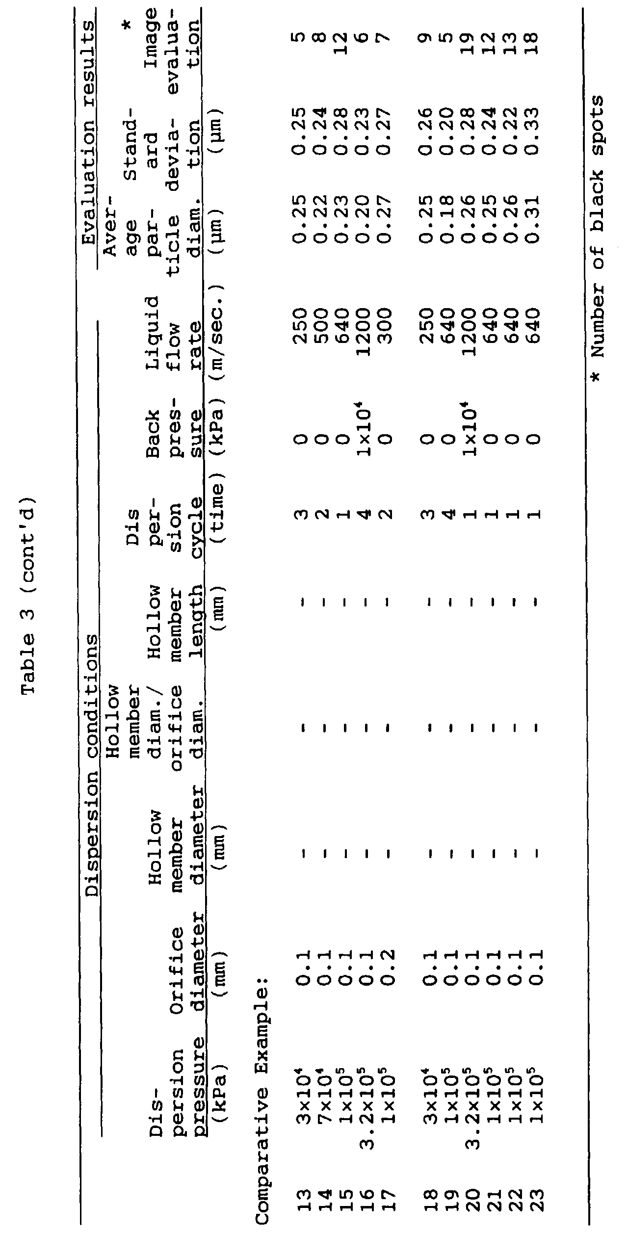


| Dispersion pressure or number of revolutions | Dispersion cycle or time | Fluid flow rate | Back pressure | Average particle diameter | 0.5 µm or larger coarse particle percentage |
| | | | (kPa) | (µm) | (%) |
| Example 45 |
| 6×10⁴ kPa: | Once | 350 m/sec | 0 | 0.20 | 5 |
| Twice | 350 m/sec | 0 | 0.16 | 4 |
| Three times | 350 m/sec | 0 | 0.14 | 3 |
| 1×10⁵ kPa: | Once | 500 m/sec | 1×10³ | 0.18 | 4 |
| Twice | 500 m/sec | 1×10³ | 0.14 | 3 |
| Three times | 500 m/sec | 1×10³ | 0.13 | 2 |
| 2×10⁵ kPa: | Once | 700 m/sec | 2×10³ | 0.16 | 3 |
| Twice | 700 m/sec | 2×10³ | 0.13 | 1 |
| Three times | 700 m/sec | 2×10³ | 0.13 | 1 |
| Comparative Example 38 |
| 6×10⁴ kPa: | Once | 350 m/sec | 0 | 0.24 | 13 |
| Twice | 350 m/sec | 0 | 0.20 | 8 |
| Three times | 350 m/sec | 0 | 0.20 | 8 |
| Four times | 350 m/sec | 0 | 0.22 | 11 |
| Five times | 350 m/sec | 0 | 0.24 | 11 |
| 1×10⁵ kPa: | Once | 500 m/sec | 0 | 0.20 | 8 |
| Twice | 500 m/sec | 0 | 0.20 | 7 |
| Three times | 500 m/sec | 0 | 0.22 | 10 |
| Four times | 500 m/sec | 0 | 0.24 | 11 |
| Five times | 500 m/sec | 0 | 0.28 | 15 |
| Comparative Example 39 |
| 500 rpm: | 30 minutes | - | - | 1.15 | 95 |
| 60 minutes | - | - | 1.05 | 85 |
| 120 minutes | - | - | 0.92 | 70 |
| 1,000 rpm: | 30 minutes | - | - | 0.90 | 68 |
| 60 minutes | - | - | 0.82 | 60 |
| 120 minutes | - | - | 0.75 | 55 |
| 2,000 rpm: | 30 minutes | - | - | 0.72 | 52 |
| 60 minutes | - | - | 0.72 | 40 |
| 120 minutes | - | - | 0.52 | 38 |
| | Initial potential | Potential after running | Photosensitive member defects | Running scrape | Image evaluation |
| | Light area | Residual | Light area | Residual |
| | (V) | (V) | (V) | (V) |
| Example Photosensitive Member: |
| 1 | -130 | -55 | -250 | -120 | No defects | 13 µm | Substantially good, but 1 or 2 microscopic line scratch mark(s). |
| 3 | -130 | -55 | -250 | -120 | No defects | 13 µm | Good images free of scratch marks. |
| 4 | -130 | -50 | -240 | -120 | No defects | 13 µm | Substantially good, but 1 or 2 microscopic line scratch mark(s). |
| 6 | -130 | -50 | -230 | -110 | No defects | 12 µm | Good images free of scratch marks. |
| 7 | -120 | -45 | -230 | -110 | No defects | 12 µm | Good images free of scratch marks. |
| 9 | -120 | -45 | -220 | -110 | No defects | 12 µm | Good images free of scratch marks. |
| Comparative Photosensitive Member: |
| 1 | -130 | -55 | -270 | -140 | No defects | 14 µm | 8-10 line scratch marks on halftones. |
| 3 | -130 | -55 | -260 | -140 | No defects | 14 µm | 8-10 line scratch marks on halftones. |
| 5 | -130 | -55 | -260 | -130 | No defects | 13 µm | 6-8 line scratch marks on halftones. |
| 6 | -130 | -55 | -260 | -130 | No defects | 13 µm | 8-10 line scratch marks on halftones. |
| 8 | -130 | -55 | -250 | -120 | No defects | 13 µm | 6-8 line scratch marks on halftones. |
| 10 | -130 | -55 | -250 | -120 | No defects | 13 µm | 6-8 line scratch marks on halftones. |
| 11 | -170 | -75 | -290 | -160 | 15-20 aggl. | 15 µm | Many peripheral-direction line scratch marks on halftones.(20 or more lines) |
| 13 | -150 | -70 | -290 | -160 | 15-20 aggl. | 15 µm | ditto (20 or more lines) |
| 14 | -150 | -75 | -290 | -160 | 15-20 aggl. | 15 µm | ditto (20 or more lines) |
| 16 | -150 | -70 | -280 | -155 | 10-15 aggl. | 15 µm | ditto (20 or more lines) |
| 17 | -150 | -65 | -280 | -160 | 10-15 aggl. | 15 µm | ditto (20 or more lines) |
| 19 | -140 | -65 | -280 | -150 | 5-10 aggl. | 14 µm | ditto (15-20 lines) |
| | Initial stage halftone images | Halftone images after running |
| Example Photosensitive Member: |
| 10 | Very good images free of spots and scratch marks. | Very good images free of spots and scratch marks, but 1 or 2 microscopic line scratch mark(s). |
| 12 | Very good images free of spots and scratch marks. | Good images free of spots and scratch marks. |
| 13 | Very good images free of spots and scratch marks. | Good images free of spots and scratch marks. |
| 15 | Very good images free of spots and scratch marks. | Good images free of spots and scratch marks. |
| 16 | Very good images free of spots and scratch marks. | Good images free of spots and scratch marks. |
| 18 | Very good images free of spots and scratch marks. | Good images free of spots and scratch marks. |
| Comparative Photosensitive Member: |
| 20 | Uneven on the whole, and 5-10 black spots on images. | Good images free of spots and scratch marks. |
| 22 | 5-10 black spots on images. | 5-8 peripheral-direction line scratch marks ascribable to black spots. |
| Comparative Photosensitive Member: |
| 24 | 5-10 black spots on images. | 5-8 peripheral-direction line scratch marks ascribable to black spots. |
| 25 | Good. | 5-8 peripheral-direction line scratch marks ascribable to black spots. |
| 27 | Good. | 5-8 peripheral-direction line scratch marks ascribable to black spots. |
| 29 | Uneven on the whole, and 5-10 black spots on images. | 5-8 peripheral-direction line scratch marks ascribable to black spots. |
| 30 | Unevenness is conspicuous and 15-20 black spots on images. | 15 or more peripheral-direction line scratch marks ascribable to black spots. |
| 32 | Unevenness is conspicuous and 15-20 black spots on images. | 15 or more peripheral-direction line scratch marks ascribable to black spots. |
| 33 | Unevenness is conspicuous and 15-20 black spots on images. | 15 or more peripheral-direction line scratch marks ascribable to black spots. |
| 35 | Unevenness is conspicuous and 15-20 black spots on images. | 15 or more peripheral-direction line scratch marks ascribable to black spots. |
| 36 | Unevenness is conspicuous and 15-20 black spots on images. | 10 or more peripheral-direction line scratch marks ascribable to black spots. |
| 38 | Unevenness is conspicuous and 15-20 black spots on images. | 10 or more peripheral-direction line scratch marks ascribable to black spots. |
-
A process for producing an electrophotographic
photosensitive member has a layer. The process has the
step of forming the layer by the use of a dispersion
obtained by ejecting a pressurized fluid from an
orifice into a hollow member having a diameter larger
than the diameter of the orifice, to disperse a
material to be dispersed. The fluid is ejected in
substantially an unatomized state.


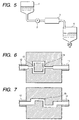
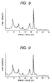
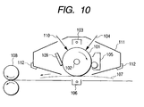

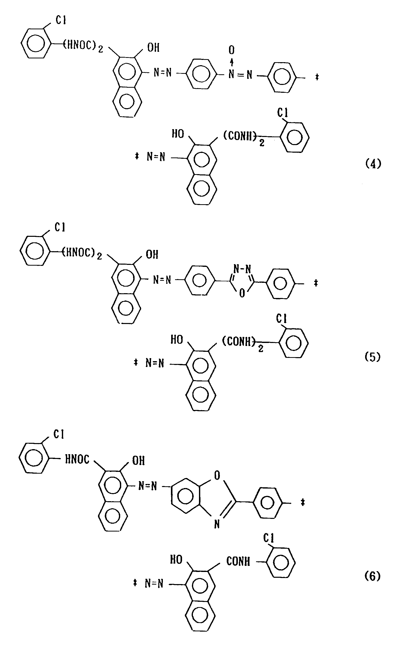
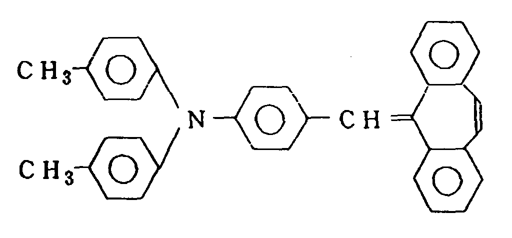


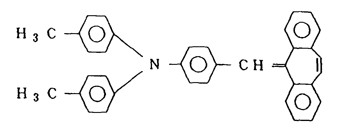
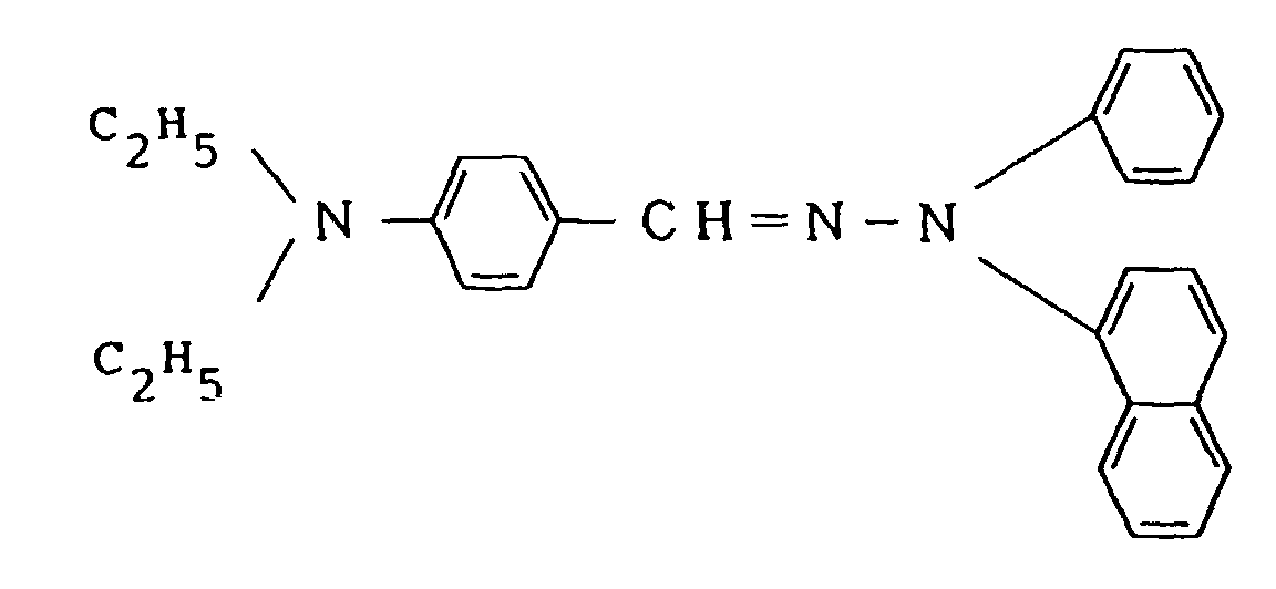
 (weight-average molecular weight: (1.6±0.3) × 105; degree of benzalation: 80 to 70), and 800 parts of cyclohexanone were put into a sand mill making use of glass beads, and dispersion was carried out to prepare a charge generation layer coating material. This coating material was dip-coated on the intermediate layer to form a charge generation layer with a dried coating weight of 200 mg/m2.
 were dissolved to obtain a charge transport layer coating material, which was then dip-coated on the charge generation layer, followed by drying to provide a charge transport layer with a dried layer thickness of 25 µm.


