EP1018640B1 - Torsional vibration measuring instrument and torsional vibration measuring method - Google Patents
Torsional vibration measuring instrument and torsional vibration measuring method Download PDFInfo
- Publication number
- EP1018640B1 EP1018640B1 EP98905815A EP98905815A EP1018640B1 EP 1018640 B1 EP1018640 B1 EP 1018640B1 EP 98905815 A EP98905815 A EP 98905815A EP 98905815 A EP98905815 A EP 98905815A EP 1018640 B1 EP1018640 B1 EP 1018640B1
- Authority
- EP
- European Patent Office
- Prior art keywords
- period
- rotational
- data
- datum
- angle
- Prior art date
- Legal status (The legal status is an assumption and is not a legal conclusion. Google has not performed a legal analysis and makes no representation as to the accuracy of the status listed.)
- Expired - Lifetime
Links
- 238000000034 method Methods 0.000 title claims description 32
- 238000001514 detection method Methods 0.000 claims description 9
- 238000004364 calculation method Methods 0.000 claims description 4
- 101100018717 Mus musculus Il1rl1 gene Proteins 0.000 claims 2
- 101150006985 STE2 gene Proteins 0.000 claims 2
- 101150023394 ste4 gene Proteins 0.000 claims 2
- 239000011295 pitch Substances 0.000 description 15
- 238000006073 displacement reaction Methods 0.000 description 13
- 238000010586 diagram Methods 0.000 description 9
- 238000005259 measurement Methods 0.000 description 7
- 238000005070 sampling Methods 0.000 description 7
- 238000004458 analytical method Methods 0.000 description 6
- 230000014509 gene expression Effects 0.000 description 4
- 238000012545 processing Methods 0.000 description 4
- 238000010276 construction Methods 0.000 description 3
- 230000001133 acceleration Effects 0.000 description 2
- 238000007405 data analysis Methods 0.000 description 2
- 238000004880 explosion Methods 0.000 description 2
- 238000012935 Averaging Methods 0.000 description 1
- 244000182067 Fraxinus ornus Species 0.000 description 1
- 230000006835 compression Effects 0.000 description 1
- 238000007906 compression Methods 0.000 description 1
- 238000013500 data storage Methods 0.000 description 1
- 238000013461 design Methods 0.000 description 1
- 230000000694 effects Effects 0.000 description 1
- 238000010248 power generation Methods 0.000 description 1
- 230000000630 rising effect Effects 0.000 description 1
- 238000010008 shearing Methods 0.000 description 1
- 230000001960 triggered effect Effects 0.000 description 1
- 230000000007 visual effect Effects 0.000 description 1
Images






Classifications
-
- G—PHYSICS
- G01—MEASURING; TESTING
- G01H—MEASUREMENT OF MECHANICAL VIBRATIONS OR ULTRASONIC, SONIC OR INFRASONIC WAVES
- G01H1/00—Measuring characteristics of vibrations in solids by using direct conduction to the detector
- G01H1/10—Measuring characteristics of vibrations in solids by using direct conduction to the detector of torsional vibrations
Definitions
- the present invention relates to a torsional vibration measuring instrument according to the preamble portion of claim 1 and a torsional vibration measuring method especially for measuring the fluctuation of displacement of rotational angle of a rotary shaft in a diesel engine and the like for shipboard or electric power generation.
- a rotary shaft of a shipboard large diesel engine or the like for transmitting power to a load is subject to torsional vibration caused by intermittent explosion in a piston or pistons of the engine, thereby producing resonance with natural frequency according to the length of the rotary shaft. From standpoints of safety and basic performance capacities, the torsional vibration must be detected for preventing the engine from such resonance and noise. Conventionally, there has been used an instrument for measring such torsional vibration.
- a load 5 is supplied with the rotational driving power from a driving source 1 like an engine through a rotary shaft 2.
- a gear 3 which has a determined number of teeth, is fixed onto a certain portion of rotary shaft 2.
- Gear 3 and a pickup 4, e.g. electromagnetically operated, which is opposed to gear 3, constitute a rotation detector (hereinafter, an encoder).
- Pickup 4 detects rotation pulses every rotation of rotary shaft 2 at a predetermined angle ⁇ , and transmits the detected pulses to an input terminal T 1 of a torsion vibration measuring instrument 6.
- Rotation pulses through input terminal T 1 is amplified by an amplifier 7, and is transmitted to a phase detecting circuit 9 of a phase lock loop (PLL) 8, so as to measure the phase displacement between the pulses from pickup 4 and those generated by a voltage control oscillating (VCO) circuit 11.
- PLL phase lock loop
- VCO voltage control oscillating
- the detected phase displacement signal is smoothed through a low pass filter (LPF) 10.
- LPF 10 low pass filter
- the signal filtrated by LPF 10 is changed by VCO 11 into a voltage corresponding to a natural frequency in proportion to the rotational speed of rotary shaft 2 without torsional vibration.
- VCO 11 outputs reference pulses with a frequency corresponding to the voltage, so as to transmit them to both of phase detecting circuit 9 and a phase displacement measuring circuit 12.
- Phase displacement measuring circuit 12 also receives rotation pulses to be measured from the encoder through amplifier 7.
- phase displacement measuring circuit 12 is configurated to calculate the digital value of displacement between both the inputs every input period, i.e., the phase displacement between the reference pulse from VCO 11 and the rotation pulse to be measured from the encoder, which corresponds to the angular fluctuation generated by the torsional vibration of rotary shaft 2, so as to transmit it to an output terminal T 3 .
- Output terminal T 3 has been connected through a code or the like with a recorder 13 to be penned, an FFT (a fast Fourier transform) analyzer 14 or the like for record and analysis of a torsion angle in relation to a crank angle or rotational angle.
- FFT fast Fourier transform
- the torsional vibration measuring instrument disclosed in Japanese Laid Open Gazette No. Hei 6-307922 is perfectly digitized so as to free its measuring range from the capacities of circuits.
- Fig. 12 the components coinciding with those in Fig. 11 are marked by the same reference numerals without description.
- a striped tape 3a is stuck to the periphery of rotary shaft 2, and a pair of photosensors 4a and 4b such as photodiodes are disposed at reference angles ⁇ from a surface which is perpendicular to the longitudinal direction of rotary shaft 2 and opposite to tape 3a.
- the rotation pulses output from photosensors 4a and 4b pass through input terminals T 1 and T 2 and first and second amplifiers 7a and 7b, respectively, so as to be inputted into a digital processing circuit 15 in torsional vibration measuring instrument 6.
- Digital processing circuit 15 comprises a period calculating unit, a sample period measuring unit, a sum averaging unit, a rotation angle displacement fluctuation calculating unit and the like, so as to send a calculated signal ⁇ of fluctuation of rotation angle displacement of rotary shaft 2 to first output terminal T 3 .
- Various pulse shapes are analyzed from fluctuation signal ⁇ by FFT analyzer 14 or the like which is connected with first output terminal T 3 .
- fluctuation signal ⁇ is sent to a second output terminal T 4 through a digital-analog convertor (DAC) 16, so as to be recorded by recorder 13 connected to second output terminal T 4 .
- DAC digital-analog convertor
- the above-said conventional digitalized torsional vibration measuring instrument has involved the problem that a distance between opposed photosensors 4a and 4b above tape 3a must be smaller than the pitch of each stripe on tape 3a, thereby requiring a long time for the burdensome arrangement of photosensors 4a and 4b and making the instrument expensive.
- US-A-5 390 545 discloses an apparatus for measuring torsional vibrations of rotating machinery and having the features of the preamble of claim 1.
- the present invention provides a torsional vibration measuring instrument and a torsional vibration measuring method for solving the above problems.
- An object of the invention is to obtain a miniaturized portable torsional vibration measuring instrument, which can be placed in a narrow space of a ship, a power plant or the like, memorize the torsional vibration data fast with reliablity and diplay the memorized data, and to obtain a method for such measurement by use of the instrument.
- An aspect of the invention is to obtain a torsional vibration measuring instrument including a striped tape stuck onto a rotary shaft and a torsional vibration measuring method, wherein, when the rotational period between juxtaposed stripes of the tape across a seam thereon is different from that between regularly juxtaposed stripes thereof (when the fluctuation of rotational angle displacement between the juxtaposed stripes across the seam is large), the different period across the seam is replaced with the average of the forward and rearward periods, thereby avoiding the nerve-racking adjustment of the seam and the detection jump across the seam.
- the torsional vibration measuring instrument of the present invention comprises the features of claim 1.
- the torsional vibration measuring method of the present invention comprises the features of claim 3.
- FIG. 1 illustrates the torsional vibration measuring method by use of the torsional vibration measuring instrument according to the present invention.
- a driving source 1 like a diesel engine gives rotational force onto a rotary shaft 2.
- a piston or pistons repeat suction, compression, expansion and exhaust processes thereof in a cylinder or cylinders of driving source 1. Except while the expansion process caused by explosion, rotary shaft 2 receives force corresponding to a load 5 against the rotational force given by driving source 1, so that a torsional moment works on rotary shaft 2.
- a shearing strain ⁇ on the surface of rotary shaft 2.
- a striped tape 3a which has white and black stripes in alternate order is stuck onto a predetermined portion, e.g. a midway, of rotary shaft 2 of a length L.
- Photosensor 4a like a photo diode detects light reflected from the tape 3a, so that rotation pulse lines are supplied into a portable torsion vibration measuring instrument (hereinafter, data logger) 6. It will be appreciable that, if rotary shaft 2 is provided with a gear 3, an electromagnetic pickup 4 may be disposed to face to teeth of gear 3, as shown in FIG. 11 .
- Data logger 6 comprising a miniaturized casing logs the rotation pulse line into intermittent ones every a predetermined number of rotation of rotary shaft 2.
- Data logger 6 has a display means 34 like an LCD, which can display at least the rotational speed and the torsional amplitude, and an operation unit 29 with a numeric keypad and the like. Additionally, data logger 6 has a storage means 24 like an S-RAM card or a memory flush, which can be removed from the casing.
- Storage means 24 which has recorded data from data logger 6 can be attached to a portable data analyzing/processing device (hereinafter, notebook PC) 35, so that, when a printer or the like is connected with notebook PC 35, the result of analysis in a worksite can be printed out.
- notebook PC portable data analyzing/processing device
- RS-232C or the like which has been conventionally used is not used for connection between storage means 24 and notebook PC 35, thereby transmitting the data therebetween fast. Only several exchanges of storage means 24 are required to store data in volume.
- notebook PC 35 has softwares for analyzing the strain and the torsional angle in relation to the rotational speed, the torsional angle in relation to the number of rotation (or to the frequency) and in relation to the crankshaft angle. The analysis result can be printed out as a report 37.
- main PC 36 a data analyzing/processing device placed in a remote factory, design office or the like by telephone line or satellite, so that the data recorded at the worksite can be analyzed at such a remote site rapidly and the results thereof as a report 38 can be printed out in real time.
- FIG. 2 showing a flow diagram of data logger 6 according to the present invention
- pickup 4 and gear 3 or striped tape 3a and photosensor 4a are provided as an encoder.
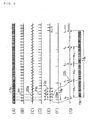
- the rotation pulse lines picked up by such detection means are sent into input terminal T 1 of data logger 6 as shown in FIG. 3B .
- Input terminal T 1 is connected to amplifier 7.
- the signal output from amplifier 7 is transmitted into a latching circuit 22 and a cycle dividing circuit 25 via a differentiating circuit 20 and a monostable multi vibrator (hereinafter, MM) 21.
- MM monostable multi vibrator
- a clock oscillator 17 generates a clock singnal 17a consisting of referrence pulses at a predetermined frequency. e.g., of 16MHz as shown in FIG. 3A .
- Clock signal 17a is received by a counter 19 via a count starting switch 18, when being closed, in operation unit 29, so that counter 19 freely runs to start counting.
- the count signals from counter 19 are supplied into latching circuit 22.
- Latching circuit 22 latches the counts from counter 19 every pulse line from the encoder, and storage means 24 records the latched data via writing circuit 23.
- Both of the data from latching circuit 22 and from cycle dividing circuit 25 are supplied into average calculating unit 26 so as to calculate an average of periods corresponding to the pulse lines during one rotation, in other words, a time for one rotation.
- the average data calculated by average calculating unit 26 is supplied into a rotational speed calculating unit 27 and a torsion angle calculating unit 32.
- Rotational speed calculating unit 27 calculates the rotational speed every period during one rotation, and each resulting rotational speed is displayed by display means 34.
- torsional angle calculating unit 32 is also provided with the latched data from latch circuit 22, so as to calculate a torsional angle.
- the torsional angle data from torsional angle calculating circuit 32 is supplied into an amplitude calculating unit 33, so as to calculate the difference between the reference rotational angle and the measured rotational angle, whereby the data of difference between the maximum and minimum every rotation of rotary shaft 2 is outputted so as to be displayed as a value of torsional amplitude by display means 34.
- a microcomputer (hereinafter, CPU) 28 is provided with conventional ROM (read only memory) 30 and RAM (random access memory) 31 and with operation unit 29 including the numeric keypad and the like.
- CPU 28 interchanges data through buses 35 with writing circuit 23, storage means 24, cycle dividing circuit 25, average calculating circuit 26, rotational speed calculating circuit 27, torsional angle calculating circuit 32, amplitude calculating circuit 33, display means 34 and the like and control them for calculation by the circuits or the means or writing data on storage means 24.
- Detected pulses 4n which are detected by electromagnetic pickup 4 or photosensor 4a of the encoder are amplified by amplifier 7 as shown in FIG. 3B , and are differentiated at their rising and trailing edges by differentiating circuit 20 as shown in FIG. 3C .
- MM 21 is triggered by the differentiated pulses from, e.g. the trailing edges of the detected pulses 4n, so as to provide short pulse lines 21a serving as short timing signals corresponding to respective detected pulses 4n.
- Timing signals 21a are supplied to latching circuit 22.
- Clock singnals 17a illustrated by FIG. 3A are counted by counter 19 simultaneously with the closing of starting switch 18.
- the counts 17a by counter 19 are latched by latching circuit 22 every timing signal and the number of the counts 17a is recorded by storage means 24 like S-RAM via writing circuit 23.
- values of counts each of which corresponds to each of periods ⁇ 1 to ⁇ n between adjacent timing pulses, as shown in FIG. 3E are stored in storage means 24.
- Cycle dividing circuit 25 delimits timing signals 21a from MM 21 every number N corresponding to one rotation of rotary shaft 2, so as to output dividing signals 25a every number N of timing pulses 21a, as shown in FIG. 3F .
- the number N is that of the same colored stripes of tape 3a or of teeth of gear 3.
- Average calculating circuit 26 sums the total of dividing signals 25a n ⁇ 1 to n ⁇ n every dividing signal 25a and divides the total by number N, so as to calculate an average A of counts every rotational period ⁇ n .
- the average of clock-counts counted every period during one rotation of rotary shaft 2 is calculated. If the rotational speed of rotary shaft 2 is constant, the counts increases in proportion to the length of time t 1 . t 2. ⁇ t n corresponding to one rotation.
- the resulting data of average calculating circuit 26 is transmitted into rotational speed calculating circuit 27, and CPU 28 calculates an average rotational speed (r.p.m.) corresponding to one period, i.e. one rotation/N by the expression 60/period.
- torsional angle calculating circuit 32 calculates a torsional angle from average A output from average calculating circuit 26 and real pulse lines latched every period of ⁇ 1 to ⁇ n by latching circuit 22, in other words, count values n ⁇ 1 to n ⁇ n .
- Torsional angle ⁇ is equal to average A subtracted from an ideal count value corresponding to the predetermined rotational angle.
- Amplitude calculating circuit 33 calculates a fluctuation of torsional angle displacement ⁇ from an ideal angle l/N, e.g., of a rotation of rotary shaft 2 and from real torsional angle ⁇ calculated by torsional angle calculating circuit 32 and outputs the difference between the maximum value and the minimum value every rotation as an amplitude value, which is displayed together with a rotational speed (r.p.m.) by display means 34 of data logger 6.
- the rotational speed of rotary shaft 2 or the average thereof is constant, it is increased in proportion to the number of counts, so that the angle may be represented as the value of counts.
- Each of count values (A) to (G) corresponds to each of count numbers 0 to 6, as shown in FIG. 4B , so as to define each of angles 0°, 60°, 120°, 180°, 240°, 300°, and 360°.
- the ideal count value corresponding to each rotational speed is given by following expressions, wherein Ix is proportionally divided:
- the amplitude of torsional angle displacement and the rotational speed can be displayed by data logger 6 so that a judgement as to whether it is right or not can be made while measuring in a worksite, thereby solving the problem caused by the conventional measurement employing a remote FFT analyzer that it occasionally happens that a datum found to be unstored after analysis by the FFT analyzer must be restored in the worksite.
- storage means 24 like S-RAM is removably attached to data logger 6 for recording the data about the measured rotational speed and torsional angle, and the frequency analysis or the like is performed by portable notebook PC 35 separated from data logger 6, thereby minimizing data logger 6, so that the data can be cetainly recorded in a narrow place like that in a ship for a limited short time.
- the data produced by data logger 6 can be transferred to a designing department in a factory or the like in real time, or be recorded by storage means 24 to be checked afterward.
- Data logger 6 has such various advantages.
- the preferred embodiment is provided to enable striped tape 3a to be stuck to rotary shaft 2 regardless of the diameter of rotary shaft 2 to be measured so as to avoid such the above complicated work in a worksite.
- Tape 3a is painted with the same color, black, across the seam thereof, thereby extending the black stripe including the seam, so that data logger 6 can read the extended black stripe without visual counting so as to calculate the torsinal angle and the rotational speed.
- the white stripe which is the closest to the seam is filled in with black by a pen or the like, so as to create a recognizablely extended black stripe across the seam with a pitch between 1.5P mm to 3.5P mm which is different from the pitches of any other black stripes.
- a white part 41 is cut away from a leading end 40 so that the remaining white stripe as a beginning end part 42 to be stuck has a pitch of 2P/3 mm.
- Tape 3a is wound around rotary shaft 2 once. Then, if a boundary 45 between white beginning end part 42 and a juxtaposed black stripe overlaps with a winding-up black stripe 43 so as to be apart from a boundary between winding-up black stripe 43 and a white stripe 44 immediately before winding-up black stripe 43 with a pitch A between 0 mm and P/2 mm, white stripe 44 is filled in with black.
- Winding-up black stripe 43 is cut along a cut line 46 as a seam within its part of a pitch B between overlapping boundary 45 and the last end of winding-up black stripe 43.
- the resulting extended last black stripe has a pitch between 3P mm and 3.5P mm.
- boundary 45 of tape 3a once wound around rotary shaft 2 overlapping with winding-up black stripe 43 is apart from a boundary between winding-up black stripe 43 and a white stripe 44 immediately before winding-up black stripe 43 with a pitch A' between P/2 mm and P mm white stripe 44 is left as it is while winding-up black stripe 43 is cut along cut line 46 as a seam within its part of pitch B between overlapping boundary 45 and the last end of winding-up black stripe 43.
- the resulting extended last black stripe has a pitch between 1.5P mm and 2.0P mm.
- winding-up black stripe is extended between 1.5P mm and 3.5P mm (150% and 350%) corresponding to the above some different situations of tape 3a wound around rotary shaft 2.
- CPU 28 in data logger 6 can count the number of several pulses caused by one rotation of rotary shaft 2 with tape 3a having the several same colored stripes.
- CPU 28 detects the first maximum interval S ⁇ MAX immediately before the aforemost pulse (as shown in FIG. 6B ), which is caused by extended black stripe 43 including the seam.
- the last maximum interval E ⁇ MAX (as shown in FIG. 6B ) is detected.
- the pulse next to the last maximum interval E ⁇ MAX is counted, and is added to the above counts of pulses, thereby summing a total of pulses 47 during one rotation of rotary shaft 2.
- a fifth step S 5 the rotational speed and the torsional angle are calculated as detailed in FIG. 2 , on the basis of the total number of pulses.
- data logger 6 of the preferred embodiment can display the rotational speed of the engine where the datum is unrecorded immediately after the data record.
- FIG. 7 illustrates a flow chart of a process by CPU 28 when there is such an unrecorded datum.
- each datum is input into the CPU corresponding to each of rotational speeds between a first speed S 1 (min. r.p.m.) and a last speed S n (Max. r.p.m.), which are determined by the table in storage means 24.
- a second step ST 2 data recording starts, and when the rotational speed of rotary shaft 2 reaches first speed S 1 , a datum is recorded in correspondence to first rotational speed S 1 according to a third step S 3 .
- CPU 28 checks whether there has been recorded the datum or not. When there is no recorded datum, the rotational speed is displayed by display means 34 according to a fifth step ST 5 , At a seventh step ST 7, the rotational speed is increased to the next determined, and then the process is returned to fourth step ST 4.
- step ST 4 If a datum is detected to be recorded at fourth step ST 4 . the process is advanced to a sixth step ST 6, when there is decided whether it is the last step or not. In other words, the judgement whether the rotational speed is larger than last determined rotational speed S n or not. If it is so, the process reaches its end. If it is not, the rotational speed is increased to the next determined according to seventh step ST 7 , so that the detection of recorded datum at fourth step ST 4 and the following steps ST 5 to 8 are repeated.
- display means 34 can display the rotational speed when the datum is unrecorded, so that the unrecorded datum can be recorded while data logger 6 remains in connection with the engine.
- FIG. 8A shows that photosensor 4a has a plurality of sensor elements 48 and 49 made of photo couplers, photo interrupters or the like, which are disposed with a certain pitch P, therebetween corresponding to black stripes, e.g., of striped tape 3a.
- the outputs of sensor elements 48 and 49 are summed through respective resistences R 1 and R 2 . so as to be supplied to a reversing input terminal of a differential amplifier 50 while the non-reversing input terminal thereof is connected with the earth.
- a feedback resistence R 3 is interposed between an output terminal 51 and the reversing input terminal of differential amplifier 50.
- ResistenceR 3 equals R 1 /2 or R 2 /2 both which are equal to each other, so that both outputs of sensor elements 48 and 49 are summed in the same phase except the difference of pitch P 1 .
- the output voltage -e 0 of differential amplifier 50 on the assumption that the output voltages of sensor elements 48 and 49 are designated as E A and E B, respectively, equals E A + E B /2.
- the output of differential amplifier 50 is averaged, thereby being accurate.
- the analogue wave shape obtained by output terminal 51 is changed into a pulse line through a wave shape forming circuit (not shown), so as to be supplied into input terminal T 1 .
- a reference numeral 54 designates an element caused by the seam of striped tape 3a.
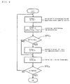
- a first step STE 1 is provided to read sample data each of which is a number N of total clock counts from the first count every rotational angle corresponding to a predetermined number of rotation (until e.g. a rotational angle of 5760 corresponding to 16 rotations).
- a period between a sampling time and a sampling time immediately before or after is calculated.
- period data ⁇ T n-1 ( T n - T n-1 ).
- ⁇ T n ( T n+1 - T n ).
- period datum ⁇ T n is compared with a predetermined threshold Xc
- ⁇ T n is not larger than X c , a process is transferred to fifth step STE 5 beyond fourth step STE 4 .
- datum ⁇ T n is recorded again in storage means 24.
- a sixth step STE 6 is provided to judge whether the sampling is the last or not. If it is so, the process reaches the end. If it is not, the process returns to first step STE 1 for next sampling.
- the data recorded in storage means 24 of data logger 6 are clock data every detection pulse input, so that each period can be obtained by subtraction of each clock datum from that immediately after.
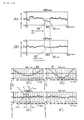
- a data fluctuation part 56 where values of data vary across a seam 55 of tape 3a, as shown in FIG. 10A , can be amended into a part 57 as shown in FIG. 10B .
- FiGs. 10A and 10B illustrate the measured torsional angle data in relation to the rotational angle (720°) of rotary shaft 2 corresponding to its 2 rotations in the condition that the rotational speed of rotary shaft 2 is 1180 r.p.m.
- FIG. 10A is of before the amendment, and FIG. 10B of after it.
- the jump of torsional angle value through seam 55 shown in FIG. 10A is made to vanish as shown in FIG. 10B .
- the torsion measurement can be prevented from mistake by the great fluctuation of data value caused by noise or the seam, and striped tape 3a can be wound and stuck onto rotary shaft 2 without complexity.
- Threshold Xc is so determined that, when a difference between one pulse period datum and the pulse period average is beyond that corresponding to theoretical torsional amplitude, the pulse period datum is amended to the average of those immediately before and after the datum.
- the data amendment is performed during the data transferring the measured data recorded in storage menas 24 like S-RAM to RAM of notebook PC 35 or main PC 36.
- the case may be supposed that torsional data are obtained every pulse period during 16 rotations of rotary shaft 2 (0 ° to 5760°) which is rotated at a predetermined certain speed (either of 580 r.p.m. and 700 r.p.m.) as shown in FIGs. 10C and 10D .
- a predetermined certain speed either of 580 r.p.m. and 700 r.p.m.
- a period between pulse timings T n-1 and T n is designated as ⁇ T n-1 , that between T n and T n+1 is as ⁇ T n , and that between T n+1 and T n+2 is as ⁇ T n+1 .
- data recording can be easily and certainly performed by the data logger for a limitted time even in a small space of a ship or a power plant.
- the data logger separated from the notebook PC for data analysis becomes small and light as long as possible, thereby being portable. Additionally, since a rotational speed and a torsional angle can be displayed by the display means of the data logger, the check whether each datum is acceptable or not, or whether each datum is recorded or not can be performed in a worksite.
- the noise of torsional angle data caused by the seam of the striped tape or by the sensor can be amended by the method that the maximum amplitude of torsional angle during a rotation is averaged by the forward and rearward values, whereby a data jump caused across the seam of the tape can be amended so as to be analyzed. Even if there is some fluctuation of rotational speed, data can be stored, thereby reducing the time for measurement.
- the torsional vibration measuring instrument has a portable data logger separated from a notebook PC as a data analyzer, so that data recording and judgement of the data can be performed in such a worksite as a narrow place in a ship or a power plant.
Landscapes
- Physics & Mathematics (AREA)
- General Physics & Mathematics (AREA)
- Measurement Of Mechanical Vibrations Or Ultrasonic Waves (AREA)
Description
- The present invention relates to a torsional vibration measuring instrument according to the preamble portion of
claim 1 and a torsional vibration measuring method especially for measuring the fluctuation of displacement of rotational angle of a rotary shaft in a diesel engine and the like for shipboard or electric power generation. - A rotary shaft of a shipboard large diesel engine or the like for transmitting power to a load is subject to torsional vibration caused by intermittent explosion in a piston or pistons of the engine, thereby producing resonance with natural frequency according to the length of the rotary shaft. From standpoints of safety and basic performance capacities, the torsional vibration must be detected for preventing the engine from such resonance and noise. Conventionally, there has been used an instrument for measring such torsional vibration.
- Referring to
Fig. 11 showing the system of the conventional analog torsional vibration measuring instrument (disclosed in Japanese Utility Patent Application NoSho 61-12026 load 5 is supplied with the rotational driving power from adriving source 1 like an engine through arotary shaft 2. - A
gear 3, which has a determined number of teeth, is fixed onto a certain portion ofrotary shaft 2. Gear 3 and apickup 4, e.g. electromagnetically operated, which is opposed togear 3, constitute a rotation detector (hereinafter, an encoder). -
Pickup 4 detects rotation pulses every rotation ofrotary shaft 2 at a predetermined angle θ, and transmits the detected pulses to an input terminal T1 of a torsionvibration measuring instrument 6. - Rotation pulses through input terminal T1 is amplified by an
amplifier 7, and is transmitted to aphase detecting circuit 9 of a phase lock loop (PLL) 8, so as to measure the phase displacement between the pulses frompickup 4 and those generated by a voltage control oscillating (VCO)circuit 11. - The detected phase displacement signal is smoothed through a low pass filter (LPF) 10. The signal filtrated by
LPF 10 is changed byVCO 11 into a voltage corresponding to a natural frequency in proportion to the rotational speed ofrotary shaft 2 without torsional vibration.VCO 11 outputs reference pulses with a frequency corresponding to the voltage, so as to transmit them to both ofphase detecting circuit 9 and a phasedisplacement measuring circuit 12. - Phase
displacement measuring circuit 12 also receives rotation pulses to be measured from the encoder throughamplifier 7. - As disclosed in Japanese Patent No.
Sho 57-6052 displacement measuring circuit 12 is configurated to calculate the digital value of displacement between both the inputs every input period, i.e., the phase displacement between the reference pulse fromVCO 11 and the rotation pulse to be measured from the encoder, which corresponds to the angular fluctuation generated by the torsional vibration ofrotary shaft 2, so as to transmit it to an output terminal T3. Output terminal T3 has been connected through a code or the like with arecorder 13 to be penned, an FFT (a fast Fourier transform)analyzer 14 or the like for record and analysis of a torsion angle in relation to a crank angle or rotational angle. - The torsional vibration measuring instrument disclosed in Japanese Laid Open Gazette No.
Hei 6-307922 Fig. 12 , is perfectly digitized so as to free its measuring range from the capacities of circuits. InFig. 12 , the components coinciding with those inFig. 11 are marked by the same reference numerals without description. Furthermore, astriped tape 3a is stuck to the periphery ofrotary shaft 2, and a pair ofphotosensors rotary shaft 2 and opposite totape 3a. - The rotation pulses output from
photosensors second amplifiers digital processing circuit 15 in torsionalvibration measuring instrument 6.Digital processing circuit 15 comprises a period calculating unit, a sample period measuring unit, a sum averaging unit, a rotation angle displacement fluctuation calculating unit and the like, so as to send a calculated signal Δθ of fluctuation of rotation angle displacement ofrotary shaft 2 to first output terminal T3. Various pulse shapes are analyzed from fluctuation signal Δθ byFFT analyzer 14 or the like which is connected with first output terminal T3. Furthermore, fluctuation signal Δ is sent to a second output terminal T4 through a digital-analog convertor (DAC) 16, so as to be recorded byrecorder 13 connected to second output terminal T4. This torsinal vibration measring instrument can detect the seam ontape 3a certainly by timers ofphotosensors - The above-said conventional digitalized torsional vibration measuring instrument has involved the problem that a distance between opposed
photosensors tape 3a must be smaller than the pitch of each stripe ontape 3a, thereby requiring a long time for the burdensome arrangement ofphotosensors - Furthermore, the same instrument has been of an installed type requiring a large casing. When the torsional vibration measurement is to be performed at a worksite in a factory or the like,
recorder 13 andFFT analyzer 14 must be carried together with such a large instrument. -
US-A-5 390 545 discloses an apparatus for measuring torsional vibrations of rotating machinery and having the features of the preamble ofclaim 1. - The present invention provides a torsional vibration measuring instrument and a torsional vibration measuring method for solving the above problems. An object of the invention is to obtain a miniaturized portable torsional vibration measuring instrument, which can be placed in a narrow space of a ship, a power plant or the like, memorize the torsional vibration data fast with reliablity and diplay the memorized data, and to obtain a method for such measurement by use of the instrument.
- An aspect of the invention is to obtain a torsional vibration measuring instrument including a striped tape stuck onto a rotary shaft and a torsional vibration measuring method, wherein, when the rotational period between juxtaposed stripes of the tape across a seam thereon is different from that between regularly juxtaposed stripes thereof (when the fluctuation of rotational angle displacement between the juxtaposed stripes across the seam is large), the different period across the seam is replaced with the average of the forward and rearward periods, thereby avoiding the nerve-racking adjustment of the seam and the detection jump across the seam.
- The torsional vibration measuring instrument of the present invention comprises the features of
claim 1. - The torsional vibration measuring method of the present invention comprises the features of
claim 3. -
-
FIG. 1 is an operational diagram of a torsional vibration measuring method by use of a torsional vibration measuring instrument according to the present invention; -
FIG. 2 is a flow diagram of the torsional vibration measuring instrument according to the present invention; -
FIGs. 3 are wave form charts by the torsional vibration measuring instrument according to the present invention; -
FIGs. 4 are diagrams showing a relationship between the number (value) of counts and the rotational angle according to the present invention; -
FIGs. 5 are diagrams showing some marking processes of striped tapes; -
FIGs. 6 are a flow sheet and a diagram showing a process of counting pulses during one rotation of the tape; -
FIG. 7 is a flow sheet of a data storage process including a routine for unrecorded data according to the present invention; -
FIGs. 8 are a schematic diagram of detection process by use of a plurality of sensors and graphs showing the effect thereof, -
FIG. 9 is a flow sheet of a process for amending the detected signal across a seam of the striped tape; -
FIG. 10 are wave form charts in result from the process shown inFIG. 9 ; -
FIG. 11 is an operational diagram of a conventional torsional vibration measuring instrument, and -
FIG. 12 is another operational diagram of a conventional torsional vibration measuring instrument. - An explanation will be given on a torsional vibration measuring instrument and a torsional vibration measuring method in accordance with
FIGs. 1 to 10 . -
FIG. 1 illustrates the torsional vibration measuring method by use of the torsional vibration measuring instrument according to the present invention. Adriving source 1 like a diesel engine gives rotational force onto arotary shaft 2. A piston or pistons repeat suction, compression, expansion and exhaust processes thereof in a cylinder or cylinders ofdriving source 1. Except while the expansion process caused by explosion,rotary shaft 2 receives force corresponding to aload 5 against the rotational force given bydriving source 1, so that a torsional moment works onrotary shaft 2. In order to measure a shearing strain γ, on the surface ofrotary shaft 2. astriped tape 3a which has white and black stripes in alternate order is stuck onto a predetermined portion, e.g. a midway, ofrotary shaft 2 of alength L. Photosensor 4a like a photo diode detects light reflected from thetape 3a, so that rotation pulse lines are supplied into a portable torsion vibration measuring instrument (hereinafter, data logger) 6. It will be appreciable that, ifrotary shaft 2 is provided with agear 3, anelectromagnetic pickup 4 may be disposed to face to teeth ofgear 3, as shown inFIG. 11 . -
Data logger 6 comprising a miniaturized casing logs the rotation pulse line into intermittent ones every a predetermined number of rotation ofrotary shaft 2.Data logger 6 has a display means 34 like an LCD, which can display at least the rotational speed and the torsional amplitude, and anoperation unit 29 with a numeric keypad and the like. Additionally,data logger 6 has a storage means 24 like an S-RAM card or a memory flush, which can be removed from the casing. - Storage means 24 which has recorded data from
data logger 6 can be attached to a portable data analyzing/processing device (hereinafter, notebook PC) 35, so that, when a printer or the like is connected with notebook PC 35, the result of analysis in a worksite can be printed out. - RS-232C or the like which has been conventionally used is not used for connection between storage means 24 and notebook PC 35, thereby transmitting the data therebetween fast. Only several exchanges of storage means 24 are required to store data in volume. Notebook PC 35 has softwares for analyzing the strain and the torsional angle in relation to the rotational speed, the torsional angle in relation to the number of rotation (or to the frequency) and in relation to the crankshaft angle. The analysis result can be printed out as a
report 37. - Additionally, data can be communicated from notebook PC 35 to a data analyzing/processing device (hereinafter, main PC) 36 placed in a remote factory, design office or the like by telephone line or satellite, so that the data recorded at the worksite can be analyzed at such a remote site rapidly and the results thereof as a
report 38 can be printed out in real time. - Referring toFIG. 2 showing a flow diagram of
data logger 6 according to the present invention, eitherpickup 4 andgear 3 orstriped tape 3a andphotosensor 4a are provided as an encoder. The rotation pulse lines picked up by such detection means are sent into input terminal T1 ofdata logger 6 as shown inFIG. 3B . - Input terminal T1 is connected to
amplifier 7. The signal output fromamplifier 7 is transmitted into a latchingcircuit 22 and acycle dividing circuit 25 via a differentiating circuit 20 and a monostable multi vibrator (hereinafter, MM) 21. - A
clock oscillator 17 generates aclock singnal 17a consisting of referrence pulses at a predetermined frequency. e.g., of 16MHz as shown inFIG. 3A .Clock signal 17a is received by acounter 19 via acount starting switch 18, when being closed, inoperation unit 29, so that counter 19 freely runs to start counting. The count signals from counter 19 are supplied into latchingcircuit 22. - Latching
circuit 22 latches the counts from counter 19 every pulse line from the encoder, and storage means 24 records the latched data via writingcircuit 23. - Both of the data from latching
circuit 22 and fromcycle dividing circuit 25 are supplied into average calculatingunit 26 so as to calculate an average of periods corresponding to the pulse lines during one rotation, in other words, a time for one rotation. - The average data calculated by average calculating
unit 26 is supplied into a rotationalspeed calculating unit 27 and a torsionangle calculating unit 32. - Rotational
speed calculating unit 27 calculates the rotational speed every period during one rotation, and each resulting rotational speed is displayed by display means 34. - In addition to the resulting data from average calculating
circuit 26, torsionalangle calculating unit 32 is also provided with the latched data fromlatch circuit 22, so as to calculate a torsional angle. - The torsional angle data from torsional
angle calculating circuit 32 is supplied into anamplitude calculating unit 33, so as to calculate the difference between the reference rotational angle and the measured rotational angle, whereby the data of difference between the maximum and minimum every rotation ofrotary shaft 2 is outputted so as to be displayed as a value of torsional amplitude by display means 34. - A microcomputer (hereinafter, CPU) 28 is provided with conventional ROM (read only memory) 30 and RAM (random access memory) 31 and with
operation unit 29 including the numeric keypad and the like.CPU 28 interchanges data through buses 35 with writingcircuit 23, storage means 24,cycle dividing circuit 25,average calculating circuit 26, rotationalspeed calculating circuit 27, torsionalangle calculating circuit 32,amplitude calculating circuit 33, display means 34 and the like and control them for calculation by the circuits or the means or writing data on storage means 24. - The operational process of
data logger 6 in the above construction will be described as follows in accordance withFIG. 3 illustrating the wave shape charts thereof. - Detected
pulses 4n which are detected byelectromagnetic pickup 4 orphotosensor 4a of the encoder are amplified byamplifier 7 as shown inFIG. 3B , and are differentiated at their rising and trailing edges by differentiating circuit 20 as shown inFIG. 3C . Next, MM 21 is triggered by the differentiated pulses from, e.g. the trailing edges of the detectedpulses 4n, so as to provideshort pulse lines 21a serving as short timing signals corresponding to respective detectedpulses 4n. - Timing signals 21a are supplied to latching
circuit 22.Clock singnals 17a illustrated byFIG. 3A are counted by counter 19 simultaneously with the closing of startingswitch 18. Thecounts 17a by counter 19 are latched by latchingcircuit 22 every timing signal and the number of thecounts 17a is recorded by storage means 24 like S-RAM via writingcircuit 23. In other words, values of counts each of which corresponds to each of periods τ1 to τn between adjacent timing pulses, as shown inFIG. 3E , are stored in storage means 24. -
Cycle dividing circuit 25 delimits timing signals 21a from MM 21 every number N corresponding to one rotation ofrotary shaft 2, so as tooutput dividing signals 25a every number N of timingpulses 21a, as shown inFIG. 3F . The number N is that of the same colored stripes oftape 3a or of teeth ofgear 3. - Both counts 22a latched by latching
circuit 22 and dividingsignal 25a output fromcycle dividing circuit 25 are transmitted into average calculatingcircuit 26. Average calculatingcircuit 26 sums the total of dividingsignals 25a nτ1 to nτn everydividing signal 25a and divides the total by number N, so as to calculate an average A of counts every rotational period τn. The calculation is performed byCPU 28 on the basis of data through average calculatingcircuit 26. This is given by the next expression (1):
- Thus, the average of clock-counts counted every period during one rotation of
rotary shaft 2 is calculated. If the rotational speed ofrotary shaft 2 is constant, the counts increases in proportion to the length of time t1. t2. ··· tn corresponding to one rotation. - The resulting data of average calculating
circuit 26 is transmitted into rotationalspeed calculating circuit 27, andCPU 28 calculates an average rotational speed (r.p.m.) corresponding to one period, i.e. one rotation/N by theexpression 60/period. - Next, torsional
angle calculating circuit 32 calculates a torsional angle from average A output from average calculatingcircuit 26 and real pulse lines latched every period of τ1 to τn by latchingcircuit 22, in other words, count values nτ1 to nτn. Torsional angle θ is equal to average A subtracted from an ideal count value corresponding to the predetermined rotational angle. -
Amplitude calculating circuit 33 calculates a fluctuation of torsional angle displacement Δθ from an ideal angle l/N, e.g., of a rotation ofrotary shaft 2 and from real torsional angle θ calculated by torsionalangle calculating circuit 32 and outputs the difference between the maximum value and the minimum value every rotation as an amplitude value, which is displayed together with a rotational speed (r.p.m.) by display means 34 ofdata logger 6. - If the rotational speed of
rotary shaft 2 or the average thereof is constant, it is increased in proportion to the number of counts, so that the angle may be represented as the value of counts. Whenrotary shaft 2 is provided with a 6-pulse sensor, which generates six detection pulses every rotation ofrotary shaft 2, the torsional angle corresponding to one rotation ofrotary shaft 2 is a count value I x (=(G)-(A)) corresponding to one rotation ofrotary shaft 2, as shown inFIGs. 4A and 4B . Each of count values (A) to (G) corresponds to each ofcount numbers 0 to 6, as shown inFIG. 4B , so as to define each ofangles 0°, 60°, 120°, 180°, 240°, 300°, and 360°. The ideal count value corresponding to each rotational speed is given by following expressions, wherein Ix is proportionally divided: - (A) = Ix * 0/360
- (B) = Ix * 60/360
- (C) = Ix * 120/360
- (D) = Ix * 180/360
- (E) Ix * 240/360
- (F) Ix * 300/360
- (G) = Ix * 360/360
- Thus, torsional angle θ is calculated by the next expression:

- The amplitude of torsional angle displacement and the rotational speed can be displayed by
data logger 6 so that a judgement as to whether it is right or not can be made while measuring in a worksite, thereby solving the problem caused by the conventional measurement employing a remote FFT analyzer that it occasionally happens that a datum found to be unstored after analysis by the FFT analyzer must be restored in the worksite. - Furthermore, storage means 24 like S-RAM is removably attached to
data logger 6 for recording the data about the measured rotational speed and torsional angle, and the frequency analysis or the like is performed by portable notebook PC 35 separated fromdata logger 6, thereby minimizingdata logger 6, so that the data can be cetainly recorded in a narrow place like that in a ship for a limited short time. The data produced bydata logger 6 can be transferred to a designing department in a factory or the like in real time, or be recorded by storage means 24 to be checked afterward.Data logger 6 has such various advantages. - Detailed desciption will be given on the process to windingly stick striped
tape 3a ontorotary shaft 2 in accordance withFIGs. 5A, 5B and 5C andFIGs. 6A and 6B . - Conventionally, in the case that the pitch of each of a white stripe and a black stripe of
tape 3a is P mm (like that shown inFIG. 5A ),tape 3a must have been provided aroundrotary shaft 2 so that the stripe thereof which is the closest to a seam is more than P/2 mm for improving the acuracy of measurement. Such restriction requiring the seam adjustment taking a long time, while diameters ofrotary shafts 2 are different from one another, has complicated the work for stickingstriped tape 3a torotary shaft 2. Furthermore, before the rotational speed and torsional angle measurement bydata logger 6, the number of stripes oftape 3a stuck onto eachrotary shaft 2 must be visually counted and input intodata logger 6. - The preferred embodiment is provided to enable
striped tape 3a to be stuck torotary shaft 2 regardless of the diameter ofrotary shaft 2 to be measured so as to avoid such the above complicated work in a worksite.Tape 3a is painted with the same color, black, across the seam thereof, thereby extending the black stripe including the seam, so thatdata logger 6 can read the extended black stripe without visual counting so as to calculate the torsinal angle and the rotational speed. - As shown in
FIGs. 5A to C , when each of white and black stripes has a pitch of P mm, the white stripe which is the closest to the seam is filled in with black by a pen or the like, so as to create a recognizablely extended black stripe across the seam with a pitch between 1.5P mm to 3.5P mm which is different from the pitches of any other black stripes. - In this regard, when windingly sticking
tape 3a torotary shaft 2, as shown inFIG. 5A , awhite part 41 is cut away from a leadingend 40 so that the remaining white stripe as a beginningend part 42 to be stuck has a pitch of 2P/3 mm.Tape 3a is wound aroundrotary shaft 2 once. Then, if aboundary 45 between whitebeginning end part 42 and a juxtaposed black stripe overlaps with a winding-upblack stripe 43 so as to be apart from a boundary between winding-upblack stripe 43 and awhite stripe 44 immediately before winding-upblack stripe 43 with a pitch A between 0 mm and P/2 mm,white stripe 44 is filled in with black. Winding-upblack stripe 43 is cut along acut line 46 as a seam within its part of a pitch B between overlappingboundary 45 and the last end of winding-upblack stripe 43. The resulting extended last black stripe has a pitch between 3P mm and 3.5P mm. - As shown in
FIG. 5B ifboundary 45 oftape 3a once wound aroundrotary shaft 2 overlapping with winding-upblack stripe 43 is apart from a boundary between winding-upblack stripe 43 and awhite stripe 44 immediately before winding-upblack stripe 43 with a pitch A' between P/2 mm and P mmwhite stripe 44 is left as it is while winding-upblack stripe 43 is cut alongcut line 46 as a seam within its part of pitch B between overlappingboundary 45 and the last end of winding-upblack stripe 43. The resulting extended last black stripe has a pitch between 1.5P mm and 2.0P mm. - As shown in
FIG. 5C , if the winding-up oftape 3a once wound aroundrotary shaft 2 is inwhite stripe 44 so thatboundary 45 overlaps with winding-upwhite stripe 44, a part C of winding-upwhite stripe 44 between overlappingboundary 45 and the last end ofblack stripe 43 just before winding-upwhite stripe 44 is filled in with black and is intermediately cut alongcut line 46 as a seam. The resulting extended last black stripe has a pitch between 2.0P mm and 3.0P mm. - Thus, winding-up black stripe is extended between 1.5P mm and 3.5P mm (150% and 350%) corresponding to the above some different situations of
tape 3a wound aroundrotary shaft 2. - For the purpose that the number of the same colored stripes of
tape 3a every rotation ofrotary shaft 2 can be not visually but automatically counted, conventionally, woundtape 3a must have had one colored stripe which generates one pulse. According to the preferred embodiment, as shown inFIG. 6A ,CPU 28 indata logger 6 can count the number of several pulses caused by one rotation ofrotary shaft 2 withtape 3a having the several same colored stripes. - Referring to
FIG. 6A , at a first step S1. CPU 28 detects the first maximum interval SτMAX immediately before the aforemost pulse (as shown inFIG. 6B ), which is caused by extendedblack stripe 43 including the seam. - At a second step S2. after detection of the first maximum interval SτMAX, following pulses are automatically counted one by one during one rotation of
rotary shaft 2. - At a third step S3, the last maximum interval EτMAX (as shown in
FIG. 6B ) is detected. At a fourth step S4, the pulse next to the last maximum interval EτMAX is counted, and is added to the above counts of pulses, thereby summing a total ofpulses 47 during one rotation ofrotary shaft 2. - At a fifth step S5, the rotational speed and the torsional angle are calculated as detailed in
FIG. 2 , on the basis of the total number of pulses. - Explanation will now be given on another construction for recording data of torsional amplitude according to the present invention. In such a case that several rotational speeds of an engine for recording the data are determined while the engine is gradually accelerated, the tables corresponding to the respective determined rotational speeds have been previously recorded in
RAM 31 or storage means 24 forCPU 28, and then the datum is recorded by storage means on every rotational speed. However, since the acceleration of the engine is manually operated, it may happen that the acceleration is too fast to record the datum on the moment that the rotational speed reaches the predetermined. - Conventionally, such an unrecorded datum has not been able to be recognized before the data analysis by the FFT analyzer or the like, so that
dada logger 6 has had to be taken again to the vicinity of the engine for recording the unrecorded datum. To avoid the problem,data logger 6 of the preferred embodiment can display the rotational speed of the engine where the datum is unrecorded immediately after the data record. -
FIG. 7 illustrates a flow chart of a process byCPU 28 when there is such an unrecorded datum. - At a first step ST1, each datum is input into the CPU corresponding to each of rotational speeds between a first speed S1 (min. r.p.m.) and a last speed Sn (Max. r.p.m.), which are determined by the table in storage means 24.
- At a second step ST2. data recording starts, and when the rotational speed of
rotary shaft 2 reaches first speed S1, a datum is recorded in correspondence to first rotational speed S1 according to a third step S3. - At a fourth step ST3.
CPU 28 checks whether there has been recorded the datum or not. When there is no recorded datum, the rotational speed is displayed by display means 34 according to a fifth step ST5, At a seventh step ST7, the rotational speed is increased to the next determined, and then the process is returned tofourth step ST 4. - If a datum is detected to be recorded at fourth step ST4. the process is advanced to a sixth step ST6, when there is decided whether it is the last step or not. In other words, the judgement whether the rotational speed is larger than last determined rotational speed Sn or not. If it is so, the process reaches its end. If it is not, the rotational speed is increased to the next determined according to seventh step ST7, so that the detection of recorded datum at fourth step ST4 and the following steps ST5 to 8 are repeated.
- According to the preferred embodiment, immediately after every data recording, display means 34 can display the rotational speed when the datum is unrecorded, so that the unrecorded datum can be recorded while
data logger 6 remains in connection with the engine. - Referring to
FIG. 2 ,single photosensor 4a orpickup 4 is opposed tostriped tape 3a orgear 3. On the contrary,FIG. 8A shows thatphotosensor 4a has a plurality ofsensor elements striped tape 3a. The outputs ofsensor elements differential amplifier 50 while the non-reversing input terminal thereof is connected with the earth. A feedback resistence R3 is interposed between anoutput terminal 51 and the reversing input terminal ofdifferential amplifier 50. ResistenceR 3 equals R1/2 or R2/2 both which are equal to each other, so that both outputs ofsensor elements - According to the above mentioned construction, the output voltage -e0 of
differential amplifier 50, on the assumption that the output voltages ofsensor elements differential amplifier 50 is averaged, thereby being accurate. Of course, the analogue wave shape obtained byoutput terminal 51 is changed into a pulse line through a wave shape forming circuit (not shown), so as to be supplied into input terminal T1. - In the state that the rotational speed of
rotary shaft 2 is 46 r.p.m., the data recording of the torsinal amplitude in relation to the rotational angle when using two sensor elements as shown inFIG. 8B is perfectly prevented from any noise element, in comparison with that when using a single sensor element as shown inFIG. 8C which causesnoise elements reference numeral 54 designates an element caused by the seam ofstriped tape 3a. - Next, detailed explanation will be given on a method for amendment of ones caused at the seam of
tape 3a or the noisy position in the data recorded in storage means 24 like S-RAM bydata logger 6, which are, for example, of fixed frequency to be analyzed by the FFT analyzer or the like. - Referring to a flow chart in
FIG. 9 , a first step STE1 is provided to read sample data each of which is a number N of total clock counts from the first count every rotational angle corresponding to a predetermined number of rotation (until e.g. a rotational angle of 5760 corresponding to 16 rotations). - At a second step STE2, a period between a sampling time and a sampling time immediately before or after is calculated. In this regard,
CPU 28 subtracts the sample count number from that immediately after so as to obtain a period datum Δ Tn (= Tn+1 - Tn). Thus, period data Δ Tn-1 (= Tn - Tn-1). Δ Tn (= Tn+1 - Tn). Δ Tn+1 (= Tn+2 - Tn) and so on are obtained. - At a third step STE3, period datum ΔTn is compared with a predetermined threshold Xc,
- If ΔTn is larger than Xc, a fourth step STE1 is provided to replace sample datum ΔTn with an average of both data ΔTn-1 and Δ Tn+1 immediately before and after sample datum Δ Tn (i.e. Δ Tn = ( Δ Tn-1 + Δ Tn+1)/2), and then a process is advanced to a fifth step STE5.
- If Δ Tn is not larger than Xc, a process is transferred to fifth step STE5 beyond fourth step STE4. At fifth step STE5, datum Δ Tn is recorded again in storage means 24.
- A sixth step STE6 is provided to judge whether the sampling is the last or not. If it is so, the process reaches the end. If it is not, the process returns to first step STE1 for next sampling.
- The data recorded in storage means 24 of
data logger 6 are clock data every detection pulse input, so that each period can be obtained by subtraction of each clock datum from that immediately after. - According to the preferred embodiment which can process with the above mentioned software, a
data fluctuation part 56 where values of data vary across aseam 55 oftape 3a, as shown inFIG. 10A , can be amended into apart 57 as shown inFIG. 10B . -
FiGs. 10A and 10B illustrate the measured torsional angle data in relation to the rotational angle (720°) ofrotary shaft 2 corresponding to its 2 rotations in the condition that the rotational speed ofrotary shaft 2 is 1180 r.p.m.FIG. 10A is of before the amendment, andFIG. 10B of after it. It will be noticed that the jump of torsional angle value throughseam 55 shown inFIG. 10A is made to vanish as shown inFIG. 10B . Hence, according to such a data amending method as shown inFIG. 9 , the torsion measurement can be prevented from mistake by the great fluctuation of data value caused by noise or the seam, andstriped tape 3a can be wound and stuck ontorotary shaft 2 without complexity. - Threshold Xc is so determined that, when a difference between one pulse period datum and the pulse period average is beyond that corresponding to theoretical torsional amplitude, the pulse period datum is amended to the average of those immediately before and after the datum.
- In the preferred embodiment, the data amendment is performed during the data transferring the measured data recorded in storage menas 24 like S-RAM to RAM of notebook PC 35 or
main PC 36. Then, the case may be supposed that torsional data are obtained every pulse period during 16 rotations of rotary shaft 2 (0 ° to 5760°) which is rotated at a predetermined certain speed (either of 580 r.p.m. and 700 r.p.m.) as shown inFIGs. 10C and 10D . When the start of data sampling at therotational angle 0°, the rotational speed has become either 500 or 700 r.p.m. constantly. However, when the fininshing thereof at therotational angle 5760°, there appears fluctuation of rotation, whereby the data of the starting and finishing ends do not agree with each other. The resultingspeed variety graphs 60 and 61 at therotational speeds FIGs. 10C and 10D , thereby making analysis of the data difficult. Then, as shown inFIG. 10E , it may be supposed that a pulse timing at an angle 1500 ° is designated as Tn-1, the next at 2160° is as Tn, the further next at 2520° is as Tn+1, and so on. A period between pulse timings Tn-1 and Tn is designated as ΔTn-1, that between Tn and T n+1 is as ΔTn, and that between Tn+1 and Tn+2 is as ΔTn+1. When it is decided that ΔTn is larger than Xc at fourth step STE4 of the flow chart shown inFIG. 9 , period ΔTn is replaced with the average of Δ Tn-1 and Δ Tn+1 ( Δ Tn = (Δ Tn-1 and Δ Tn+1)/2). Accordingly,speed variety graphs 60 and 61 shown inFIGs. 10C and 10D can be amended into those 62 and 63 shown inFIGs. 10E and 10F , so that even if the rotational speed at the last sampling is different from that at the first sampling. - According to the present invention as the above, data recording can be easily and certainly performed by the data logger for a limitted time even in a small space of a ship or a power plant. The data logger separated from the notebook PC for data analysis becomes small and light as long as possible, thereby being portable. Additionally, since a rotational speed and a torsional angle can be displayed by the display means of the data logger, the check whether each datum is acceptable or not, or whether each datum is recorded or not can be performed in a worksite.
- Since the data of rotational speed and torsional angle are recorded in a memory flush or a memory card, the capacities thereof can be analyzed by a notebook PC or a main PC after data recording.
- The noise of torsional angle data caused by the seam of the striped tape or by the sensor can be amended by the method that the maximum amplitude of torsional angle during a rotation is averaged by the forward and rearward values, whereby a data jump caused across the seam of the tape can be amended so as to be analyzed. Even if there is some fluctuation of rotational speed, data can be stored, thereby reducing the time for measurement.
- The torsional vibration measuring instrument according to the present invention has a portable data logger separated from a notebook PC as a data analyzer, so that data recording and judgement of the data can be performed in such a worksite as a narrow place in a ship or a power plant.
Claims (3)
- A torsional vibration measuring instrument comprising:a detection means (3a,4a) for detecting, of an object (2) to be rotated, a rotational period (τn) every predetermined angle of one rotation thereof;a detachable and portable storage means (24) for recording said detected rotational periods (τn);an average calculation means (26) for calculating an average (A) of said detected rotational periods (τn);a torsional angle calculation means (32) for calculating a torsional angle (Θ) of said object (2) on the basis of said calculated average (A) of said detected rotational periods (τn) and said detected rotational periods (τn); anda display means (34) for displaying at least an amplitude of said torsional angle (Θ);characterized in thatsaid detection means (3a,4a) comprises a striped tape (3a) disposed around the periphery of said object (2); andsaid torsional vibration measuring instrument further comprises:means for reading sample data each of which is a number N of total clock counts from the first count every rotational angle corresponding to a predetermined number of rotations;a calculating means (STE2) for obtaining a period datum (ΔTn) of a rotational period and period data (ΔTn-1,ΔTn+1) of rotational periods immediately before and after said rotational period by subtracting successive sample data;a comparison means (STE3) for comparing said calculated period datum (ΔTn) with a threshold value (Xc); andan amendment means (STE4) for replacing, when said calculated period datum (ΔTn) is determined to be larger than said threshold value (Xc), said calculated period datum (ΔTn) with an average of said period data (ΔTn-1,ΔTn+1) immediately before and after said rotational period.
- A torsional vibration measuring instrument as set forth in claim 1, wherein said striped tape (3a) is colored across a seam thereof.
- A torsional vibration measuring method comprising:detecting, of an object (2) to be rotated, a rotational period (τn) every predetermined angle of one rotation thereof by means of a striped tape (3a) disposed around the periphery of said object (2);recording said detected rotational periods (τn);calculating an average (A) of said detected rotational periods (τn);calculating a torsional angle (Θ) of said object (2) on the basis of said calculated average (A) of said detected rotational periods (τn) and said detected rotational periods (τn);displaying at least an amplitude of said torsional angle (Θ);reading sample data each of which is a number N of total clock counts from the first count every rotational angle corresponding to a predetermined number of rotationsobtaining (STE2) a period datum (ΔTn) of a rotational period and period data (ΔTn-1,ΔTn+1) of rotational periods immediately before and after said rotational period by subtracting successive sample data;comparing (STE3) said calculated period datum (ΔTn) with a threshold value (Xc); andreplacing (STE4), when said calculated period datum (ΔTn) is determined to be larger than said threshold value (Xc), said calculated period datum (ΔTn) with an average of said period data (ΔTn-1, ΔTn+1) immediately before and after said rotational period.
Applications Claiming Priority (3)
| Application Number | Priority Date | Filing Date | Title |
|---|---|---|---|
| JP06091297A JP3852152B2 (en) | 1997-03-14 | 1997-03-14 | Torsional vibration measuring device |
| JP6091297 | 1997-03-14 | ||
| PCT/JP1998/000958 WO1998041821A1 (en) | 1997-03-14 | 1998-03-09 | Torsional vibration measuring instrument and torsional vibration measuring method |
Publications (3)
| Publication Number | Publication Date |
|---|---|
| EP1018640A1 EP1018640A1 (en) | 2000-07-12 |
| EP1018640A4 EP1018640A4 (en) | 2005-11-23 |
| EP1018640B1 true EP1018640B1 (en) | 2008-05-21 |
Family
ID=13156076
Family Applications (1)
| Application Number | Title | Priority Date | Filing Date |
|---|---|---|---|
| EP98905815A Expired - Lifetime EP1018640B1 (en) | 1997-03-14 | 1998-03-09 | Torsional vibration measuring instrument and torsional vibration measuring method |
Country Status (5)
| Country | Link |
|---|---|
| US (1) | US6421615B1 (en) |
| EP (1) | EP1018640B1 (en) |
| JP (1) | JP3852152B2 (en) |
| DE (1) | DE69839521D1 (en) |
| WO (1) | WO1998041821A1 (en) |
Cited By (1)
| Publication number | Priority date | Publication date | Assignee | Title |
|---|---|---|---|---|
| US9429092B2 (en) | 2010-07-16 | 2016-08-30 | Cummins Inc. | Fault detection and response techniques |
Families Citing this family (14)
| Publication number | Priority date | Publication date | Assignee | Title |
|---|---|---|---|---|
| DE10057054B4 (en) * | 1999-12-02 | 2013-08-08 | Schaeffler Technologies AG & Co. KG | Method for detecting vibrations |
| EP1227382A3 (en) * | 2001-01-24 | 2003-03-26 | Bombardier Transportation GmbH | Rolling stock diagnostic condition monitoring and on-line predictive maintenance |
| ATE485497T1 (en) * | 2001-12-04 | 2010-11-15 | Skf Condition Monitoring Inc | CYCLIC TIME AVERAGE FOR MACHINE MONITORING |
| WO2005017471A1 (en) * | 2003-08-14 | 2005-02-24 | Hasse & Wrede Gmbh | Method and device for measuring torsional oscillations |
| US9404791B2 (en) * | 2009-06-06 | 2016-08-02 | Nuovo Pignone S.P.A. | Lateral, angular and torsional vibration monitoring of rotordynamic systems |
| TWI404942B (en) * | 2009-12-10 | 2013-08-11 | Ind Tech Res Inst | A torsional resonance frequency measuring device and method |
| US8996335B2 (en) | 2011-12-31 | 2015-03-31 | Aktiebolaget Skf | Systems and methods for energy efficient machine condition monitoring of fans, motors, pumps, compressors and other equipment |
| US11639881B1 (en) | 2014-11-19 | 2023-05-02 | Carlos A. Rosero | Integrated, continuous diagnosis, and fault detection of hydrodynamic bearings by capacitance sensing |
| US12264986B1 (en) | 2014-11-19 | 2025-04-01 | Carlos A. Rosero | Integrated, continuous diagnosis, and fault detection of hydrodynamic bearings by capacitance sensing |
| CN105067099B (en) * | 2015-08-13 | 2018-10-16 | 南京大学(苏州)高新技术研究院 | A kind of method and system for metro environment vibration and noise joint test |
| EP3336485B1 (en) | 2016-12-15 | 2020-09-23 | Safran Landing Systems UK Limited | Aircraft assembly including deflection sensor |
| JP7316027B2 (en) * | 2018-05-24 | 2023-07-27 | 三菱重工業株式会社 | Torsional vibration measurement device for rotating shaft system |
| JP7077262B2 (en) * | 2019-03-28 | 2022-05-30 | 三菱重工エンジン&ターボチャージャ株式会社 | Rotating shaft twist amount measuring device and twist amount measuring method |
| KR102852034B1 (en) * | 2022-11-08 | 2025-08-29 | 한국전력공사 | Apparatus and Method for Measuring Axial Torsional Natural Vibration |
Family Cites Families (14)
| Publication number | Priority date | Publication date | Assignee | Title |
|---|---|---|---|---|
| JPS551712U (en) * | 1978-06-05 | 1980-01-08 | ||
| JPS551712A (en) | 1978-06-20 | 1980-01-08 | Hitachi Ltd | Electronic switch circuit |
| JPS576052A (en) | 1980-06-12 | 1982-01-12 | Nat Jutaku Kenzai | Building with piping housing space |
| JPS57179628A (en) * | 1981-04-28 | 1982-11-05 | Ishikawajima Harima Heavy Ind Co Ltd | Torsional vibration measuring apparatus for rotating shaft |
| GB2116713A (en) * | 1982-03-09 | 1983-09-28 | Tecalemit Electronics Ltd | Vibration monitoring apparatus |
| JPS59222714A (en) * | 1983-06-01 | 1984-12-14 | Mitsubishi Heavy Ind Ltd | Angular-displacement measuring device |
| JPS6112026A (en) | 1984-06-27 | 1986-01-20 | Fujitsu Ltd | Vertical type heating furnace |
| JPS62291519A (en) * | 1986-06-11 | 1987-12-18 | Mitsubishi Heavy Ind Ltd | Apparatus for measuring torsional vibration of rotary body |
| JPH0221533A (en) | 1988-07-11 | 1990-01-24 | Nec Corp | Cathode composition for electron tube |
| JPH0221533U (en) * | 1988-07-28 | 1990-02-13 | ||
| US5390545A (en) * | 1993-01-11 | 1995-02-21 | Caterpillar Inc. | Apparatus for measuring torsional vibrations of rotating machinery |
| JPH06307922A (en) * | 1993-04-23 | 1994-11-04 | Ono Sokki Co Ltd | Torsional vibrometer |
| JPH0743206A (en) * | 1993-07-30 | 1995-02-14 | Hitachi Ltd | Rotor blade vibration measuring method and device |
| JPH0933337A (en) * | 1995-07-18 | 1997-02-07 | Japan Aviation Electron Ind Ltd | Vibration analyzer |
-
1997
- 1997-03-14 JP JP06091297A patent/JP3852152B2/en not_active Expired - Lifetime
-
1998
- 1998-03-09 US US09/381,153 patent/US6421615B1/en not_active Expired - Lifetime
- 1998-03-09 EP EP98905815A patent/EP1018640B1/en not_active Expired - Lifetime
- 1998-03-09 WO PCT/JP1998/000958 patent/WO1998041821A1/en not_active Ceased
- 1998-03-09 DE DE69839521T patent/DE69839521D1/en not_active Expired - Lifetime
Cited By (1)
| Publication number | Priority date | Publication date | Assignee | Title |
|---|---|---|---|---|
| US9429092B2 (en) | 2010-07-16 | 2016-08-30 | Cummins Inc. | Fault detection and response techniques |
Also Published As
| Publication number | Publication date |
|---|---|
| JPH10253445A (en) | 1998-09-25 |
| DE69839521D1 (en) | 2008-07-03 |
| EP1018640A1 (en) | 2000-07-12 |
| JP3852152B2 (en) | 2006-11-29 |
| WO1998041821A1 (en) | 1998-09-24 |
| US6421615B1 (en) | 2002-07-16 |
| EP1018640A4 (en) | 2005-11-23 |
Similar Documents
| Publication | Publication Date | Title |
|---|---|---|
| US6421615B1 (en) | Torsional vibration measuring instrument and torsional vibration measuring method | |
| EP0608993A2 (en) | Rotating shaft vibration monitor | |
| US5699253A (en) | Nonlinear dynamic transform for correction of crankshaft acceleration having torsional oscillations | |
| US5390545A (en) | Apparatus for measuring torsional vibrations of rotating machinery | |
| US6408685B2 (en) | Method and system for measuring interference between valve and piston of an internal combustion engine | |
| US5918286A (en) | Apparatus for torque measurement on rotating shafts | |
| US4488443A (en) | Expanded range monopole torque measuring system | |
| US7415351B2 (en) | Method and device for detecting an angular position signal for an internal-combustion engine | |
| JPH0750017B2 (en) | Method of analyzing cylinder performance of internal combustion engine | |
| EP0284508A2 (en) | Torquemeter | |
| US4430606A (en) | Sheet feeding apparatus | |
| EP0710841A3 (en) | Driveline vibration analyzer | |
| JPS61155826A (en) | Method and device for measuring load moment | |
| US3939397A (en) | Method and apparatus for determining the timing angle in internal combustion engines | |
| NO753436L (en) | ||
| WO2001038885A1 (en) | Angular velocity monitor | |
| JPS6363850B2 (en) | ||
| JPH11295106A (en) | Torque sensor for elastic coupling | |
| JPH1151816A (en) | Engine simple status monitor | |
| US6427537B1 (en) | Measuring equipment | |
| JPH03167476A (en) | Number of rotations indicator | |
| JPS61205830A (en) | Method for measuring shaft horsepower | |
| SU1516809A1 (en) | Digital meter of torque and power | |
| JPS63218831A (en) | Transient shaft torque measuring apparatus | |
| JPH06307922A (en) | Torsional vibrometer |
Legal Events
| Date | Code | Title | Description |
|---|---|---|---|
| PUAI | Public reference made under article 153(3) epc to a published international application that has entered the european phase |
Free format text: ORIGINAL CODE: 0009012 |
|
| 17P | Request for examination filed |
Effective date: 19990910 |
|
| AK | Designated contracting states |
Kind code of ref document: A1 Designated state(s): DE NL |
|
| A4 | Supplementary search report drawn up and despatched |
Effective date: 20051012 |
|
| RAP1 | Party data changed (applicant data changed or rights of an application transferred) |
Owner name: YANMAR CO., LTD. |
|
| GRAP | Despatch of communication of intention to grant a patent |
Free format text: ORIGINAL CODE: EPIDOSNIGR1 |
|
| GRAS | Grant fee paid |
Free format text: ORIGINAL CODE: EPIDOSNIGR3 |
|
| GRAA | (expected) grant |
Free format text: ORIGINAL CODE: 0009210 |
|
| AK | Designated contracting states |
Kind code of ref document: B1 Designated state(s): DE NL |
|
| REF | Corresponds to: |
Ref document number: 69839521 Country of ref document: DE Date of ref document: 20080703 Kind code of ref document: P |
|
| PLBE | No opposition filed within time limit |
Free format text: ORIGINAL CODE: 0009261 |
|
| STAA | Information on the status of an ep patent application or granted ep patent |
Free format text: STATUS: NO OPPOSITION FILED WITHIN TIME LIMIT |
|
| 26N | No opposition filed |
Effective date: 20090224 |
|
| PGFP | Annual fee paid to national office [announced via postgrant information from national office to epo] |
Ref country code: DE Payment date: 20170228 Year of fee payment: 20 |
|
| PGFP | Annual fee paid to national office [announced via postgrant information from national office to epo] |
Ref country code: NL Payment date: 20170210 Year of fee payment: 20 |
|
| REG | Reference to a national code |
Ref country code: DE Ref legal event code: R071 Ref document number: 69839521 Country of ref document: DE |
|
| REG | Reference to a national code |
Ref country code: NL Ref legal event code: MK Effective date: 20180308 |