EP1017337B1 - Middle ear prosthesis - Google Patents
Middle ear prosthesis Download PDFInfo
- Publication number
- EP1017337B1 EP1017337B1 EP98902948A EP98902948A EP1017337B1 EP 1017337 B1 EP1017337 B1 EP 1017337B1 EP 98902948 A EP98902948 A EP 98902948A EP 98902948 A EP98902948 A EP 98902948A EP 1017337 B1 EP1017337 B1 EP 1017337B1
- Authority
- EP
- European Patent Office
- Prior art keywords
- middle ear
- housing
- eardrum
- ear prosthesis
- ossicle
- Prior art date
- Legal status (The legal status is an assumption and is not a legal conclusion. Google has not performed a legal analysis and makes no representation as to the accuracy of the status listed.)
- Expired - Lifetime
Links
- 210000000959 ear middle Anatomy 0.000 title claims abstract description 45
- 210000003454 tympanic membrane Anatomy 0.000 claims abstract description 41
- 230000008878 coupling Effects 0.000 claims abstract description 27
- 238000010168 coupling process Methods 0.000 claims abstract description 27
- 238000005859 coupling reaction Methods 0.000 claims abstract description 27
- 210000001050 stape Anatomy 0.000 claims abstract description 8
- 230000005540 biological transmission Effects 0.000 claims description 25
- 230000005520 electrodynamics Effects 0.000 claims description 8
- 230000033001 locomotion Effects 0.000 claims description 7
- 210000000988 bone and bone Anatomy 0.000 claims description 5
- 244000052616 bacterial pathogen Species 0.000 claims description 4
- 210000001311 petrous bone Anatomy 0.000 claims description 3
- 230000000284 resting effect Effects 0.000 abstract 1
- 210000004379 membrane Anatomy 0.000 description 9
- 239000012528 membrane Substances 0.000 description 9
- 210000003027 ear inner Anatomy 0.000 description 7
- 239000000463 material Substances 0.000 description 6
- 210000002388 eustachian tube Anatomy 0.000 description 3
- 238000012545 processing Methods 0.000 description 3
- 238000009423 ventilation Methods 0.000 description 3
- 229920000544 Gore-Tex Polymers 0.000 description 2
- RTAQQCXQSZGOHL-UHFFFAOYSA-N Titanium Chemical compound [Ti] RTAQQCXQSZGOHL-UHFFFAOYSA-N 0.000 description 2
- 230000004888 barrier function Effects 0.000 description 2
- 238000010276 construction Methods 0.000 description 2
- 230000010339 dilation Effects 0.000 description 2
- 230000002349 favourable effect Effects 0.000 description 2
- 230000006870 function Effects 0.000 description 2
- PCHJSUWPFVWCPO-UHFFFAOYSA-N gold Chemical compound [Au] PCHJSUWPFVWCPO-UHFFFAOYSA-N 0.000 description 2
- 239000012510 hollow fiber Substances 0.000 description 2
- 238000002513 implantation Methods 0.000 description 2
- 238000005259 measurement Methods 0.000 description 2
- 210000004400 mucous membrane Anatomy 0.000 description 2
- 229920001296 polysiloxane Polymers 0.000 description 2
- 238000012546 transfer Methods 0.000 description 2
- 241000894006 Bacteria Species 0.000 description 1
- 206010008642 Cholesteatoma Diseases 0.000 description 1
- 206010011878 Deafness Diseases 0.000 description 1
- 206010014016 Ear malformation Diseases 0.000 description 1
- 206010028980 Neoplasm Diseases 0.000 description 1
- 208000033809 Suppuration Diseases 0.000 description 1
- 241000700605 Viruses Species 0.000 description 1
- 210000000577 adipose tissue Anatomy 0.000 description 1
- 238000004873 anchoring Methods 0.000 description 1
- 230000009286 beneficial effect Effects 0.000 description 1
- 230000001684 chronic effect Effects 0.000 description 1
- 208000024035 chronic otitis media Diseases 0.000 description 1
- 230000001447 compensatory effect Effects 0.000 description 1
- 230000006378 damage Effects 0.000 description 1
- 208000037265 diseases, disorders, signs and symptoms Diseases 0.000 description 1
- 208000035475 disorder Diseases 0.000 description 1
- 238000005516 engineering process Methods 0.000 description 1
- 230000005284 excitation Effects 0.000 description 1
- 230000005294 ferromagnetic effect Effects 0.000 description 1
- 239000012530 fluid Substances 0.000 description 1
- 239000003292 glue Substances 0.000 description 1
- 239000010931 gold Substances 0.000 description 1
- 229910052737 gold Inorganic materials 0.000 description 1
- 239000004519 grease Substances 0.000 description 1
- 230000010370 hearing loss Effects 0.000 description 1
- 231100000888 hearing loss Toxicity 0.000 description 1
- 208000016354 hearing loss disease Diseases 0.000 description 1
- 208000014674 injury Diseases 0.000 description 1
- 230000007774 longterm Effects 0.000 description 1
- 210000001595 mastoid Anatomy 0.000 description 1
- 238000000034 method Methods 0.000 description 1
- 239000012811 non-conductive material Substances 0.000 description 1
- 230000035515 penetration Effects 0.000 description 1
- 239000011435 rock Substances 0.000 description 1
- 239000003566 sealing material Substances 0.000 description 1
- 230000000638 stimulation Effects 0.000 description 1
- 238000001356 surgical procedure Methods 0.000 description 1
- 210000001519 tissue Anatomy 0.000 description 1
- 229910052719 titanium Inorganic materials 0.000 description 1
- 239000010936 titanium Substances 0.000 description 1
- 230000009466 transformation Effects 0.000 description 1
- 230000008733 trauma Effects 0.000 description 1
- XLYOFNOQVPJJNP-UHFFFAOYSA-N water Substances O XLYOFNOQVPJJNP-UHFFFAOYSA-N 0.000 description 1
- 229910000859 α-Fe Inorganic materials 0.000 description 1
Images

Classifications
-
- A—HUMAN NECESSITIES
- A61—MEDICAL OR VETERINARY SCIENCE; HYGIENE
- A61F—FILTERS IMPLANTABLE INTO BLOOD VESSELS; PROSTHESES; DEVICES PROVIDING PATENCY TO, OR PREVENTING COLLAPSING OF, TUBULAR STRUCTURES OF THE BODY, e.g. STENTS; ORTHOPAEDIC, NURSING OR CONTRACEPTIVE DEVICES; FOMENTATION; TREATMENT OR PROTECTION OF EYES OR EARS; BANDAGES, DRESSINGS OR ABSORBENT PADS; FIRST-AID KITS
- A61F2/00—Filters implantable into blood vessels; Prostheses, i.e. artificial substitutes or replacements for parts of the body; Appliances for connecting them with the body; Devices providing patency to, or preventing collapsing of, tubular structures of the body, e.g. stents
- A61F2/02—Prostheses implantable into the body
- A61F2/18—Internal ear or nose parts, e.g. ear-drums
- A61F2002/183—Ear parts
Definitions
- the invention relates to a middle ear prosthesis with a tubular Casing.
- Such a middle ear prosthesis is known from DE 4 407 847 A1. at this is the tubular housing not only on its outward facing End area closed by an eardrum, but it is too a membrane is provided on the inside end region. This is with an artificial eardrum through an internal transmission link connected, which prestresses the eardrum and membrane inwards. The The eardrum has a larger area than the membrane. The sound transmission from the membrane to the stapes footplate is done by a small one Amount of patient's body fat. This for sound transmission required fat is outside the prosthesis.
- a middle ear prosthesis is known from EP 460 354 B1, which without a own housing needs.
- the artificial eardrum is in an outer Retaining ring clamped in a specially designed for him in Toroidal recess is used.
- the eardrum has in the middle a hole in which a thickened front area of an ossicle replacement can be clipped. In this way, the Ossicle replacement can be arranged in the room behind the artificial eardrum. Then the artificial eardrum is inserted, the front The end of the ossicle replacement snaps into the eardrum bore.
- the object of the invention is the aforementioned middle ear prosthesis to further develop that sufficient sound pressure in the inner ear and there is a safe and permanent sound transmission to the inner ear is always guaranteed.
- the middle ear prosthesis according to the invention replaces the function of sound-transmitting Apparatus of a natural middle ear as much as possible complete, it is not on the function of the natural Eustachian Tube and / or the mucous membrane of the middle ear spaces.
- the middle ear prosthesis is neither on a lining of the mucous membrane still relying on tube ventilation. It consists of one Housing that is, for example, in two parts and that is at least germ-tight is lockable. The interior of the housing is thus for outside penetration Germs not reachable.
- the housing is for the preliminary fixation of the ossicle part, in the following called the first ossicle part, the holding device provided. This will later, before the operation is completed, removed, severed, or otherwise disabled. But it can also if it is elastic enough is, remain.
- the first ossicular part is either through an artificially created opening passed through in the stapes footplate and immediately stimulates that Inner ear, or it is placed on this footplate. So that's one direct sound transmission to the inner ear guaranteed. This sound transmission cannot due to loss of coupling grease or the like be affected.
- the first ossicle part is covered by a preferably artificial eardrum and / or by an electric drive, in particular an electrodynamic one or piezoelectric drive.
- an electric drive in particular an electrodynamic one or piezoelectric drive.
- the drive is powered by an amplifier, for example the amplifier of a hearing aid.
- the interior of the housing is through the window during the operation accessible. In this way, the necessary manipulations in the Housing are made.
- the holding device is through the window accessible. The window becomes germ-proof thanks to the cover completed.
- the window can Windows, for example, between a two-part housing that consists of a Transmission part and the coupling part is provided, by making cuts or edge-side in the overlap area of both parts Recesses are provided that correspond to a certain rotational position of the two Parts form the window to each other, but in a different rotational position close completely.
- the third part and possible further Parts are designed to form or close a window area, for example by an axially displaceable cylinder.
- annular, cylindrical parts that face the coupling part and / or transmission part are rotatable and like this a window exhibit. Turning the window will either make it free or complete locked.
- the coupling part When the middle ear prosthesis is inserted surgically, the coupling part is first used, it is as good as possible with the timpani wall the oval window around the ear. As particularly preferred it has been shown here that the free end area of the coupling part Course of the respective individual relief of the medial timpani wall of a To reproduce the wearer of the middle ear prosthesis as precisely as possible. To this This way a good fit to the timpani wall is achieved and it becomes possible with a suitable connection material to achieve a secure hold of the coupling part on the timpani wall.
- the coupling part is inserted, in the case of an opening in the Stapes footplate either already provides this or will only then executed. It is preferably produced using a laser. It is straight so large that the first ossicular part fits through it.
- the first The ossicular part is preferably a thin gold or titanium wire.
- the first The ossicular part is attached to the holding device or is already on this fixed. This determination is made so that the first ossicle part in protrudes into the inner tube to a desired extent. By laying down it is guaranteed that this dimension will not fall below or exceed later becomes.
- the housing of the invention Middle ear prosthesis compared to the surrounding tissue germ-proof, preferably hermetically sealed. This ensures that the interior of the housing is protected from the ingress of germs becomes.
- the location and size of the housing of the middle ear prosthesis is extensive Measurements of petrous bone specimens sufficiently well determined. It typically there is an average maximum diameter of approximately 11 mm and a maximum length of about 20 mm.
- the housing preferably consists of the coupling part and one Transmission part, which have connecting means so that they are together can be connected to the housing.
- this is Transfer part assigned a second ossicle part. Through the window may be the connection between the two during operational deployment Ossicle parts are observed and preferably also performed.
- the housing connecting means for the mechanical attachment of the Provide housing on the rock bone of the wearer It is possible and also wanted the space of the middle ear around the prosthesis to be filled in so that the prosthesis itself has a tight fit. Through the mechanical anchoring in the bone is done during surgery and A permanent secure attachment is guaranteed even with later bumps.
- the eardrum In the case of a middle ear prosthesis with an eardrum, it has proven to be preferred to arrange the eardrum at an angle to the axis of the housing. The larger this angle is selected, the larger the area of the eardrum. Angles between 40 ° and 80 ° to the axis of the transmission part have proven favorable, in particular an angle of approximately 53 °. In this way, the preferably artificial eardrum has a non-circular shape, in particular an elliptical shape. This avoids resonances. In particular, the large receiving area for sound is also favorable. Areas of approximately 100 mm 2 are typically obtained.
- the second ossicle part either commercially available parts can be used be, for example that of Richards GmbH under the ossicle replacement offered by the trade name TILT-TORP-PORP. He has one Hollow shaft into which the first ossicular part can be inserted. Farther he has a ball joint at his other end, which makes compensatory movements possible are. This creates a largely piston-shaped, primarily allows one-dimensional movement on the inner ear fluid. Or a separate prosthesis part can be developed, the corresponds to this mechanical principle.
- the middle ear prosthesis according to the invention has a has a substantially hermetically sealed interior is ventilation the middle ear spaces, as in the natural case by the Eustachian Tube is realized, does not exist.
- a purely electrical Drive can be dispensed with pressure equalization.
- a prosthesis with an eardrum is an artificial pressure equalization device, however necessary. It consists of an externally accessible, for example outer part hidden behind the ear, as it is in a similar form bone-anchored hearing aids that work through structure-borne noise and an inner part, which is housed in the mastoid, for example.
- this inner part has a fine filter, in particular a filter that blocks against all types of microbes and viruses, here hollow fibers are particularly suitable as filter material, or it has a pressure equalization membrane.
- a fine filter in particular a filter that blocks against all types of microbes and viruses
- hollow fibers are particularly suitable as filter material, or it has a pressure equalization membrane.
- an easily movable membrane clamped completely tight in its own housing, it forms an absolute Barrier between an outer chamber connected to the outside world and an inner chamber, which in turn is connected to the interior of the prosthesis is.
- Outer part, inner part and middle ear prosthesis are over thin Hoses, in particular silicone hoses, are sealed together and permanently connected.
- the desired profile to disposal Via a high-resolution spiral computer tomogram the course can be obtained and immediately via an intermediate stage fed to a processing machine for the free end area become. On the other hand, direct measurements with rays can also be made the relief was scanned and the processing machine accordingly or controlled indirectly. Finally, the course can be mechanical be scanned, for which purpose a special scanning device was developed. The Data obtained with this scanner can be used to control a processing machine be used.
- the middle ear prosthesis has an artificial eardrum 20, which is essentially has an oval cut. In terms of area, it is larger than that Area of a normal human eardrum, for example 1.5 times as much large. It is made from a biologically suitable for use as a prosthesis Cut material, especially from Millicell HA material Millipore GmbH, made of GORE-TEX 0.1 mm from W. L. Gore & Assoc. GmbH or from flexible silicone. Millicell, Millipore, GORE-TEX and Gore are protected names. The eardrum is in practical use 20 epithelialized.
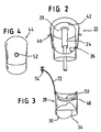
- the eardrum 20 is tightly connected to one in the embodiment shown according to the figures, two-part housing, specifically it is connected to a transmission part 22.
- This is essentially tubular. It has a substantially cylindrical area, which in figure 2 is shown below and an expanding from this Area that essentially runs on a conical surface. The diameter the cylindrical area is about 8 mm, the widening The area has corresponding dimensions of approximately 11 mm.
- FIG. 1 shows that the eardrum 20 is in one plane runs at an angle of 35 ° to a longitudinal axis 23 of the transmission part 22. Due to the inclination of the eardrum 20, the eardrum 20 a larger area than the normal ear.
- a second ossicle part 24 is permanently attached on the inside of the eardrum 20, preferably in the center of the area.
- An embodiment is a commercially available Richards ossicle replacement GmbH used. He has a ball joint near the eardrum 20, underneath there is a hollow shaft to hold one more to be discussed first part of the ossicle.
- the second ossicle part 24 runs below the ball joint centered on the central axis of the transmission part 22nd
- a coupling part 28 also belongs to the housing slightly smaller than the transmission part 22 and together with this trained, the two parts simply, tightly and permanently connected can be, especially by plugging in the longitudinal direction and Glue.
- the coupling part 28 is essentially cylindrical Diameter is also about 6 mm. It has a free end area 30, which has a course which corresponds to the respective individual relief of the The timpani wall of a wearer of the middle ear prosthesis is reproduced as precisely as possible is. The resulting individual course is special shown in Figure 3.
- the patent application "Device for mechanical scanning and recording the course of the timpani wall of a middle ear "from the same applicant and from the same filing date referenced, the disclosure content of this application becomes the subject made the disclosure of the present application.
- the free end region 30 is accordingly designed to be precise the timpani wall 32 rests, as can be seen from FIG. 1. To this A hermetically sealed closure is possible at this point, it low-viscosity fastening and sealing material can be used to the connection between the free end region 30 and the tympanic wall 32 to realize.
- a holding device 34 for the first ossicle part 26 provided in the coupling part 28 .
- the latter is designed as a thin gold wire that through a very small, artificially created opening 36 in a stapes footplate 38 extends straight through and thus with its lower, protrudes into the inner ear 40.
- the holding device 34 is a substantially diagonal Wire on which the first ossicle part 26 is or can be fixed is.
- the middle ear prosthesis is for the connection of the two ossicle parts 24, 26 and also for severing the holding device 34 requires access to the interior.
- Other Constructions without such access are possible.
- a window 42 through a cover plate 44 can be closed. It is shown in Figure 4.
- suitable mechanical holding means are provided around the cover plate 44 precise and also close to the transmission part 22 and the coupling part 28 to be able to determine.
- mandrels 46 are in the exemplary embodiment shown provided for fixing the cover plate 44, on the coupling part 28 a groove 48 for receiving the cover plate 44 through a projection educated.
- the coupling part 28 also preferably has in its upper area a recess 50, which is also used as a lower window recess referred to as.
- the cover plate 44 has a connection 52. It is for a hose 54 is provided, both of which can also be seen in FIG. 1.
- the Hose 54 leads to an inner part 56 of a pressure compensation device.
- This inner part 56 is designed as a can-shaped housing, it has two chambers, namely an outer chamber 58 and an inner chamber 60. Both are hermetically separated from each other by a very flexible membrane 62. In another version, they are through a fine filter, the is also tight against bacteria and microbes, but is permeable to air, separated from each other. Hollow fiber filters in particular come here as fine filters in question.
- the outer chamber 58 with an outer part is connected via a further hose 64 66 connected. It is anchored in a bone 76 and partially from accessible from outside, see skin 78. A construction is used here, as it is similar to so-called bone-conductive hearing aids.
- the outer part 66 has a recess 68 into which a filter 70 is inserted. This is preferably interchangeable.
- the filter 70 prevents water, Coarse dirt etc. can get into the hose 64.
- the barrier against Germs and the like are replaced by membrane 62 or that in their place pedaling fine filter reached.
- the material for the parts 22, 26, 28 and 44 and 56, 66 comes in particular Titanium into consideration.
- a Housing with an artificial eardrum 20 inserted into the housing corresponds to the first embodiment.
- a ferromagnetic core 82 in particular a core made of a Ferrite material is arranged.
- a coil 84 connected to the housing is applied outside the core 82.
- the second ossicle part 24 is made of a plastic or a other, non-conductive material. Form coil 84 and core 82 together an electrodynamic drive.
- the coil 84 is over a Lead 86 and optionally with the interposition of an implanted Amplifier 88 connected to a secondary coil 90 of a transformer.
- the secondary coil 90 is located below the skin 78 while the associated primary coil 92 is located outside the skin 78.
- the primary coil 92 is connected to the output of a hearing aid 94.
- the device installed in or receives the hearing aid 94 associated microphone sound information. They are in the hearing aid 94 strengthened and, if necessary, processed.
- the amplified signals are fed to the primary coil 92. From there they are transferred to the secondary coil 90 and thus transferred to the coil 84.
- transformer 90 To improve power transmission within transformer 90, 92 it is advisable to reduce the sound information to a implement high frequency for example of one megahertz. This happens Similar to the carrier frequency technology in telephone systems or in a corresponding one Wise.
- the movement of the Transfer the eardrum 20 to the two ossicular parts 24, 26 there are So two motion drives before.
- the ossicle parts 24, 26 through the eardrum 20 and thus directly through the eardrum 20 reaching sound moves, on the other hand by the above electrodynamic drive.
- the electrodynamic drive can only for certain frequency ranges, for example only the high frequency range, support the movement.
- hearing loss is preferred, which is only in certain frequency ranges is present, balanced.
- the electrodynamic drive can also be active in the entire frequency range.
- the housing is now only in one piece, it exists only from the coupling part 28 in which the window 42 is provided which is covered by the cover plate 44. Instead of an eardrum 20, the housing is firmly closed at the end region that the free end region 30 is opposite. So the housing is essentially cup-shaped. The closure at the end area can be used as a window instead of drawn window 42 serve.
- first ossicle part 26 Only a first ossicle part 26 is also provided, a second ossicle part eliminated.
- the first part of the ossicle is over a part running across it piezoelectric element 96 with the inner wall of the coupling part 28 connected.
- a bracket 98 is provided here.
- the piezoelectric Element 96 has the shape of an elongated plate, here as a double plate is executed. With appropriate electrical stimulation, it leads movements in the longitudinal direction of the first ossicle part 26. It's about that Lead 86 connected to the secondary coil 90 of a transformer.
- the transmission and connection with a hearing aid 94 takes place as in Exemplary embodiment according to FIG. 5.
Abstract
Description
Die Erfindung bezieht sich auf eine Mittelohrprothese mit einem rohrförmigen Gehäuse.The invention relates to a middle ear prosthesis with a tubular Casing.
Eine derartige Mittelohrprothese ist aus der DE 4 407 847 A1 bekannt. Bei dieser ist das rohrförmige Gehäuse nicht nur an seinem nach außen weisenden Endbereich durch ein Trommelfell geschlossen, sondern es ist auch an dem innenseitigen Endbereich eine Membrane vorgesehen. Diese ist mit einem künstlichen Trommelfell durch ein innenliegendes Übertragungsglied verbunden, das Trommelfell und Membrane nach innen vorspannt. Das Trommelfell hat eine größere Fläche als die Membrane. Die Schallübertragung von der Membrane an die Stapes-Fußplatte erfolgt durch eine kleine Menge körpereigenen Fetts des Patienten. Dieses für die Schallübertragung benötigte Fett liegt außerhalb der Prothese.Such a middle ear prosthesis is known from DE 4 407 847 A1. at this is the tubular housing not only on its outward facing End area closed by an eardrum, but it is too a membrane is provided on the inside end region. This is with an artificial eardrum through an internal transmission link connected, which prestresses the eardrum and membrane inwards. The The eardrum has a larger area than the membrane. The sound transmission from the membrane to the stapes footplate is done by a small one Amount of patient's body fat. This for sound transmission required fat is outside the prosthesis.
Bei dieser vorbekannten Mittelohrprothese ist es einerseits nachteilig, dass der erzielbare Schalldruck an der Stapes-Fußplatte für ein normales Hören nicht ausreichend hoch ist, weil das Flächentransformationsverhältnis verringert wird. Andererseits ist die Schallübertragungsstrecke zwischen Membran und Stapes-Fußplatte auf Dauer mit Unsicherheiten behaftet, weil schon kleinste Lufteinschlüsse im Fett oder ein Schwinden des Fettes und damit kleinste Luftspalte die Schallübertragung stark beeinflussen.With this known middle ear prosthesis, on the one hand, it is disadvantageous that the achievable sound pressure on the stapes footplate for a normal one Hearing is not high enough because of the area transformation ratio is reduced. On the other hand, the sound transmission path is between Membrane and stapes footplate have long-term uncertainties, because even the smallest air pockets in the fat or a shrinkage of the Fat and therefore the smallest air gaps have a strong influence on sound transmission.
Aus der EP 460 354 B1 ist eine Mittelohrprothese bekannt, die ohne ein eigenes Gehäuse auskommt. Das künstliche Trommelfell ist in einem äußeren Haltering eingespannt, der in eine speziell für ihn vorgesehene, im Felsenbein eingearbeitete Ausnehmung eingesetzt wird. Das Trommelfell hat in seiner Mitte ein Loch, in das ein verdickter Frontbereich eines Ossikelersatzes eingeklipst werden kann. Auf diese Weise kann zunächst der Ossikelersatz im Raum hinter dem künstlichen Trommelfell angeordnet werden. Danach wird das künstliche Trommelfell eingesetzt, das frontseitige Ende des Ossikelersatzes schnappt in die Bohrung des Trommelfells ein.A middle ear prosthesis is known from EP 460 354 B1, which without a own housing needs. The artificial eardrum is in an outer Retaining ring clamped in a specially designed for him in Toroidal recess is used. The eardrum has in the middle a hole in which a thickened front area of an ossicle replacement can be clipped. In this way, the Ossicle replacement can be arranged in the room behind the artificial eardrum. Then the artificial eardrum is inserted, the front The end of the ossicle replacement snaps into the eardrum bore.
Weitere Mittelohrprothesen sind aus EP 281 047 B1, DE 2 905 183 C3, DE 2 937 842 C3 und EP 203 785 B1 bekannt.Further middle ear prostheses are known from EP 281 047 B1, DE 2 905 183 C3, DE 2 937 842 C3 and EP 203 785 B1.
Aufgabe der Erfindung ist es, die eingangs genannte Mittelohrprothese dahingehend weiterzubilden, dass ein ausreichender Schalldruck im Innenohr vorliegt und eine sichere und dauerhafte Schallübertragung zum Innenohr stets gewährleistet ist.The object of the invention is the aforementioned middle ear prosthesis to further develop that sufficient sound pressure in the inner ear and there is a safe and permanent sound transmission to the inner ear is always guaranteed.
Ausgehend von der Mittelohrprothese der eingangs genannten Art wird diese Aufgabe gelöst durch die Merkmale des Anspruchs 1.Starting from the middle ear prosthesis of the type mentioned at the beginning, this is Problem solved by the features of claim 1.
Die erfindungsgemäße Mittelohrprothese ersetzt die Funktion des schallübertragenden Apparats eines natürlichen Mittelohrs so weit wie möglich vollständig, sie ist dabei nicht auf die Funktion der natürlichen Eustachischen Röhre und/oder der Schleimhaut der Mittelohrräume angewiesen.The middle ear prosthesis according to the invention replaces the function of sound-transmitting Apparatus of a natural middle ear as much as possible complete, it is not on the function of the natural Eustachian Tube and / or the mucous membrane of the middle ear spaces.
Die erfindungsgemäße Mittelohrprothese dient der Versorgung von Patienten mit chronischen Mittelohrentzündungen, die eine normale Schallübertragung dauerhaft schwächen oder behindern, hierzu gehören beispielsweise: Mittelohrschleimhauteiterung, Mittelohrknocheneiterung (= Cholesteatomen-Eiterung), chronische Tubenbelüftungsstörung, Mittelohr-Mißbildungen, dauerhafte Zerstörungen des Schallleitungsapparates durch Traumen und Tumoren etc.. Die Mittelohrprothese ist weder auf eine Schleimhautauskleidung noch auf eine Tubenbelüftung angewiesen. Sie besteht aus einem Gehäuse, das beispielsweise zweiteilig ist und das zumindest keimdicht abschließbar ist. Der Innenraum des Gehäuses ist damit für von außen eindringende Keime nicht erreichbar.The middle ear prosthesis according to the invention serves to care for patients with chronic otitis media, which is normal sound transmission permanently weaken or hinder, for example: Middle ear mucosal dilation, middle ear bone dilation (= cholesteatoma suppuration), chronic tube ventilation disorder, middle ear malformations, permanent destruction of the sound conduction apparatus by trauma and Tumors etc. The middle ear prosthesis is neither on a lining of the mucous membrane still relying on tube ventilation. It consists of one Housing that is, for example, in two parts and that is at least germ-tight is lockable. The interior of the housing is thus for outside penetration Germs not reachable.
Im Gehäuse ist für die vorläufige Fixierung des Ossikelteils, im folgenden erstes Ossikelteil genannt, die Halteeinrichtung vorgesehen. Diese wird später, vor Abschluß der Operation, entfernt, durchtrennt oder anderweitig außer Funktion gesetzt. Sie kann aber auch, wenn sie elastisch genug ausgebildet ist, bestehen bleiben.In the housing is for the preliminary fixation of the ossicle part, in the following called the first ossicle part, the holding device provided. This will later, before the operation is completed, removed, severed, or otherwise disabled. But it can also if it is elastic enough is, remain.
Das erste Ossikelteil ist entweder durch eine künstlich geschaffene Öffnung in der Stapes-Fußplatte hindurchgeführt und regt unmittelbar das Innenohr an, oder es ist auf diese Fußplatte aufgesetzt. Damit ist eine direkte Schallübertragung zum Innenohr gewährleistet. Diese Schallübertragung kann nicht durch Verlust von Ankopplungsfett oder dergleichen beeinträchtigt werden.The first ossicular part is either through an artificially created opening passed through in the stapes footplate and immediately stimulates that Inner ear, or it is placed on this footplate. So that's one direct sound transmission to the inner ear guaranteed. This sound transmission cannot due to loss of coupling grease or the like be affected.
Das erste Ossikelteil wird durch ein vorzugsweise künstliches Trommelfell und/oder durch einen elektrischen Antrieb, insbesondere einen elektrodynamischen oder piezoelektrischen Antrieb, bewegt. Ein derartiger elektrischer Antrieb erhält seine Spannungsversorgung durch einen Verstärker, beispielsweise den Verstärker eines Hörgerätes.The first ossicle part is covered by a preferably artificial eardrum and / or by an electric drive, in particular an electrodynamic one or piezoelectric drive. Such an electrical The drive is powered by an amplifier, for example the amplifier of a hearing aid.
Durch das Fenster ist während der Operation der Innenraum des Gehäuses zugänglich. Auf diese Weise können die notwendigen Manipulationen im Gehäuse vorgenommen werden. Insbesondere ist die Halteeinrichtung durch das Fenster zugänglich. Das Fenster wird durch das Abdeckteil keimdicht abgeschlossen.The interior of the housing is through the window during the operation accessible. In this way, the necessary manipulations in the Housing are made. In particular, the holding device is through the window accessible. The window becomes germ-proof thanks to the cover completed.
Für das Fenster sind unterschiedliche Ausbildungen möglich. So kann das Fenster beispielsweise zwischen einem zweiteiligen Gehäuse, das aus einem Übertragungsteil und dem Ankopplungsteil besteht, vorgesehen werden, indem im Überlappungsbereich beider Teile Einschnitte bzw. randseitige Aussparungen vorgesehen sind, die einer gewissen Drehposition der beiden Teile zueinander das Fenster bilden, in einer anderen Drehposition aber vollständig verschließen. Schließlich kommen auch dreiteilige und mehrteilige Gehäuse in Betracht, bei denen das dritte Teil und mögliche weitere Teile dafür bestimmt sind, einen Fensterbereich auszubilden oder zu verschließen, beispielsweise durch einen axial verschiebbaren Zylinder. Hierzu gehören auch ringförmige, zylindrische Teile, die gegenüber dem Ankopplungsteil und/oder Übertragungsteil drehbar sind und wie dieses ein Fenster aufweisen. Durch Drehen wird das Fenster entweder frei oder vollständig verschlossen.Different designs are possible for the window. So it can Windows, for example, between a two-part housing that consists of a Transmission part and the coupling part is provided, by making cuts or edge-side in the overlap area of both parts Recesses are provided that correspond to a certain rotational position of the two Parts form the window to each other, but in a different rotational position close completely. Finally, there are also three-part and multi-part Housing in question where the third part and possible further Parts are designed to form or close a window area, for example by an axially displaceable cylinder. For this also include annular, cylindrical parts that face the coupling part and / or transmission part are rotatable and like this a window exhibit. Turning the window will either make it free or complete locked.
Beim operativen Einsetzen der Mittelohrprothese wird zunächst das Ankopplungsteil eingesetzt, es ist so gut wie möglich mit der Paukenwand des Ohres ringsum das ovale Fenster verbunden. Als besonders bevorzugt hat es sich hier erwiesen, den feien Endbereich des Ankopplungsteils dem Verlauf des jeweiligen individuellen Reliefs der medialen Paukenwand eines Trägers der Mittelohrprothese möglichst genau nachzubilden. Auf diese Weise wird eine gute Passung an die Paukenwand erzielt und es wird dadurch möglich, mit einem geeigneten Verbindungsmaterial einen Abschluß und sicheren Halt des Ankopplungsteils an der Paukenwand zu erzielen.When the middle ear prosthesis is inserted surgically, the coupling part is first used, it is as good as possible with the timpani wall the oval window around the ear. As particularly preferred it has been shown here that the free end area of the coupling part Course of the respective individual relief of the medial timpani wall of a To reproduce the wearer of the middle ear prosthesis as precisely as possible. To this This way a good fit to the timpani wall is achieved and it becomes possible with a suitable connection material to achieve a secure hold of the coupling part on the timpani wall.
Wenn das Ankopplungsteil eingesetzt ist, ist im Falle einer Öffnung in der Stapes-Fußplatte entweder diese schon vorgesehen oder wird erst dann ausgeführt. Vorzugsweise wird sie mit einem Laser hergestellt. Sie ist gerade so groß, dass das erste Ossikelteil durch sie hindurchpaßt. Das erste Ossikelteil ist vorzugsweise ein dünner Gold- oder Titandraht. Das erste Ossikelteil wird an der Halteeinrichtung festgelegt oder ist bereits an dieser festgelegt. Diese Festlegung erfolgt so, dass das erste Ossikelteil in einem gewünschten Maß in das Innenrohr hineinragt. Durch die Festlegung ist gewährleistet, dass dieses Maß später nicht unter- oder überschritten wird.If the coupling part is inserted, in the case of an opening in the Stapes footplate either already provides this or will only then executed. It is preferably produced using a laser. It is straight so large that the first ossicular part fits through it. The first The ossicular part is preferably a thin gold or titanium wire. The first The ossicular part is attached to the holding device or is already on this fixed. This determination is made so that the first ossicle part in protrudes into the inner tube to a desired extent. By laying down it is guaranteed that this dimension will not fall below or exceed later becomes.
Als besonders vorteilhaft hat es sich erwiesen, dass das Gehäuse der erfindungsgemäßen Mittelohrprothese gegenüber dem umliegenden Gewebe keimdicht, vorzugsweise hermetisch abschließt. Dadurch wird gewährleistet, dass der Innenraum des Gehäuses vor dem Eindringen von Keimen geschützt wird.It has proven to be particularly advantageous that the housing of the invention Middle ear prosthesis compared to the surrounding tissue germ-proof, preferably hermetically sealed. This ensures that the interior of the housing is protected from the ingress of germs becomes.
Die Lage und Größe des Gehäuses der Mittelohrprothese ist durch umfangreiche Vermessungen von Felsenbeinpräperaten hinlänglich gut bestimmt. Es ergibt sich typischerweise ein mittlerer maximaler Durchmesser von etwa 11 mm und eine maximale Länge von etwa 20 mm.The location and size of the housing of the middle ear prosthesis is extensive Measurements of petrous bone specimens sufficiently well determined. It typically there is an average maximum diameter of approximately 11 mm and a maximum length of about 20 mm.
Vorzugsweise besteht das Gehäuse aus dem Ankopplungsteil und einem Übertragungsteil, die Verbindungsmittel aufweisen, so dass sie miteinander zu dem Gehäuse verbunden werden können. Vorzugsweise ist dabei dem Übertragungsteil ein zweites Ossikelteil zugeordnet. Durch das Fenster kann während des operativen Einsetzens die Verbindung zwischen den beiden Ossikelteilen beobachtet und vorzugsweise auch durchgeführt werden.The housing preferably consists of the coupling part and one Transmission part, which have connecting means so that they are together can be connected to the housing. Preferably this is Transfer part assigned a second ossicle part. Through the window may be the connection between the two during operational deployment Ossicle parts are observed and preferably also performed.
Für das Implantieren der Mittelohrprothese hat es sich als günstig erwiesen, am Gehäuse Verbindungsmittel für die mechanische Befestigung des Gehäuses am Felsenbein des Trägers vorzusehen. Zwar ist es möglich und auch durchaus gewollt, den Raum des Mittelohrs um die Prothese herum auszufüllen, so dass die Prothese ansich einen festen Sitz hat. Durch die mechanische Verankerung im Knochen wird während der Operation und auch bei späteren Stößen eine dauerhaft sichere Befestigung gewährleistet.For the implantation of the middle ear prosthesis, it has proven to be beneficial on the housing connecting means for the mechanical attachment of the Provide housing on the rock bone of the wearer. It is possible and also wanted the space of the middle ear around the prosthesis to be filled in so that the prosthesis itself has a tight fit. Through the mechanical anchoring in the bone is done during surgery and A permanent secure attachment is guaranteed even with later bumps.
Bei einer Mittelohrprothese mit einem Trommelfell hat es sich als bevorzugt herausgestellt, das Trommelfell in einem Winkel zur Achse des Gehäuses anzuordnen. Je größer dieser Winkel gewählt wird, um so größer wird die Fläche des Trommelfells. Günstig haben sich Winkel zwischen 40° und 80° zur Achse des Übertragungsteils erwiesen, insbesondere ein Winkel von etwa 53°. Auf diese Weise hat das bevorzugt künstliche Trommelfell eine unrunde Form, insbesondere eine elliptische Form. Dadurch werden Resonanzen vermieden. Insbesondere ist aber auch die große Empfangsfläche für Schall günstig. Es werden typischerweise Flächen von etwa 100 mm2 erhalten.In the case of a middle ear prosthesis with an eardrum, it has proven to be preferred to arrange the eardrum at an angle to the axis of the housing. The larger this angle is selected, the larger the area of the eardrum. Angles between 40 ° and 80 ° to the axis of the transmission part have proven favorable, in particular an angle of approximately 53 °. In this way, the preferably artificial eardrum has a non-circular shape, in particular an elliptical shape. This avoids resonances. In particular, the large receiving area for sound is also favorable. Areas of approximately 100 mm 2 are typically obtained.
Für das zweite Ossikelteil kann entweder auf handelsübliche Teile zurückgegriffen werden, beispielsweise den von der Firma Richards GmbH unter dem Handelsnamen TILT-TORP-PORP angebotenen Ossikelersatz. Er hat einen Hohlschaft, in den das erste Ossikelteil eingeführt werden kann. Weiterhin hat er an seinem anderen Ende ein Kugelgelenk, wodurch Ausgleichsbewegungen möglich sind. Damit wird eine weitgehend kolbenförmige, in erster Linie eindimensionale Bewegung auf die Innenohrflüssigkeit ermöglicht. Oder es kann ein eigener Prothesenteil entwickelt werden, der diesem mechanischen Prinzip entspricht.For the second ossicle part, either commercially available parts can be used be, for example that of Richards GmbH under the ossicle replacement offered by the trade name TILT-TORP-PORP. He has one Hollow shaft into which the first ossicular part can be inserted. Farther he has a ball joint at his other end, which makes compensatory movements possible are. This creates a largely piston-shaped, primarily allows one-dimensional movement on the inner ear fluid. Or a separate prosthesis part can be developed, the corresponds to this mechanical principle.
Da die erfindungsgemäße Mittelohrprothese im eingesetzten Zustand einen im wesentlichen hermetisch abgekapselten Innenraum hat, ist eine Belüftung der Mittelohrräume, wie sie im natürlichen Fall durch die Eustachische Röhre realisiert wird, nicht vorhanden. Bei einem rein elektrischen Antrieb kann man auf einen Druckausgleich verzichten. Bei einer Prothese mit einem Trommelfell ist eine künstliche Druckausgleichsvorrichtung aber notwendig. Sie besteht aus einem von außen zugänglichen, beispielsweise hinter dem Ohr verborgenen Außenteil, wie es in ähnlicher Form schon bei knochenverankerten Hörgeräten, die über Körperschall arbeiten, bekannt ist, und einem Innenteil, das beispielsweise im Mastoid untergebracht ist. Dieses Innenteil hat in einer ersten Variante ein Feinfilter, insbesondere ein Filter, das gegen jegliche Art von Mikroben und Viren sperrt, hier kommen insbesondere Hohlfasern als Filtermaterial in Frage, oder es hat eine Druckausgleichsmembran. Hierbei ist eine leicht bewegliche Membran völlig dicht in einem eigenen Gehäuse eingespannt, sie bildet eine absolute Barriere zwischen einer mit der Außenwelt verbundenen Außenkammer und einer Innenkammer, die ihrerseits mit dem Innenraum der Prothese verbunden ist. Außenteil, Innenteil und Mittelohrprothese sind über dünne Schläuche, insbesondere Silikonschläuche, miteinander dicht und dauerhaft verbunden.Since the middle ear prosthesis according to the invention has a has a substantially hermetically sealed interior is ventilation the middle ear spaces, as in the natural case by the Eustachian Tube is realized, does not exist. With a purely electrical Drive can be dispensed with pressure equalization. With a prosthesis with an eardrum is an artificial pressure equalization device, however necessary. It consists of an externally accessible, for example outer part hidden behind the ear, as it is in a similar form bone-anchored hearing aids that work through structure-borne noise and an inner part, which is housed in the mastoid, for example. In a first variant, this inner part has a fine filter, in particular a filter that blocks against all types of microbes and viruses, here hollow fibers are particularly suitable as filter material, or it has a pressure equalization membrane. Here is an easily movable membrane clamped completely tight in its own housing, it forms an absolute Barrier between an outer chamber connected to the outside world and an inner chamber, which in turn is connected to the interior of the prosthesis is. Outer part, inner part and middle ear prosthesis are over thin Hoses, in particular silicone hoses, are sealed together and permanently connected.
Um das individuelle Relief der Paukenwand eines Trägers zu erfassen und demgemäß dem freien Endbereich des Ankopplungsteils den gewünschten Verlauf, also das gewünschte Profil geben zu können, stehen mehrere Möglichkeiten zur Verfügung. Über ein hochauflösendes Spiral-Computertomogramm kann der Verlauf erhalten werden und unmittelbar über eine Zwischenstufe einer Bearbeitungsmaschine für den freien Endbereich zugeleitet werden. Andererseits kann auch über direkte Messungen mit Strahlen das Relief abgetastet und entsprechend die Bearbeitungsmaschine direkt oder indirekt gesteuert werden. Schließlich kann der Verlauf mechanisch abgetastet werden, wozu ein spezielles Abtastgerät entwickelt wurde. Die mit diesem Abtastgerät erhaltenen Daten können zur Steuerung einer Bearbeitungsmaschine eingesetzt werden.To capture the individual relief of the timpani wall of a wearer and accordingly the free end region of the coupling part the desired There are several ways to give the course, i.e. the desired profile to disposal. Via a high-resolution spiral computer tomogram the course can be obtained and immediately via an intermediate stage fed to a processing machine for the free end area become. On the other hand, direct measurements with rays can also be made the relief was scanned and the processing machine accordingly or controlled indirectly. Finally, the course can be mechanical be scanned, for which purpose a special scanning device was developed. The Data obtained with this scanner can be used to control a processing machine be used.
Weitere Vorteile und Merkmale der Erfindung ergeben sich aus den übrigen Patentansprüchen sowie der folgenden Beschreibung von nicht einschränkend zu verstehenden Ausführungsbeispielen. Die Ausführungsbeispiele werden im folgenden anhand der Zeichnung näher erläutert. In dieser zeigen:
- FIG. 1:
- eine schnittbildliche Darstellung einer Mittelohrprothese mit angesetzter Druckausgleichvorrichtung,
- FIG. 2:
- eine perspektivische Darstellung eines Übertragungsteils mit Blick auf und durch ein Arbeitsfenster,
- FIG. 3:
- eine der Darstellung gemäß Figur 2 entsprechende Darstellung eines Ankopplungsteils,
- FIG. 4:
- eine Draufsicht auf eine Abdeckplatte,
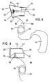
- FIG. 5:
- eine schnittbildliche Darstellung eines Gehäuses in ähnlicher Ansicht wie Figur 1, jedoch nunmehr mit zusätzlich einem elektrodynamischen Antrieb und mit einem über ein Übertragungsglied angeschlossenen externen Verstärker und
- FIG. 6:
- eine Darstellung ähnlich Figur 5, jedoch ohne Verstärker und nunmehr ohne Trommelfell, der Antrieb erfolgt ausschließlich piezoelektrisch.
- FIG. 1:
- 2 shows a sectional representation of a middle ear prosthesis with attached pressure compensation device,
- FIG. 2:
- 1 shows a perspective view of a transmission part with a view of and through a working window,
- FIG. 3:
- 2 shows a representation of a coupling part corresponding to the representation according to FIG. 2,
- FIG. 4:
- a plan view of a cover plate,
- FIG. 5:
- a sectional view of a housing in a similar view as Figure 1, but now with an additional electrodynamic drive and with an external amplifier connected via a transmission element and
- FIG. 6:
- a representation similar to Figure 5, but without an amplifier and now without an eardrum, the drive is exclusively piezoelectric.
Die Mittelohrprothese hat ein künstliches Trommelfell 20, das im wesentlichen
einen ovalen Zuschnitt hat. Der Fläche nach ist es größer als die
Fläche eines normalen menschlichen Trommelfells, beispielsweise 1,5 mal so
groß. Es ist aus einem für den Einsatz als Prothese biologisch geeigneten
Material zugeschnitten, insbesondere aus dem Material Millicell HA der
Firma Millipore GmbH, aus GORE-TEX 0,1 mm der Firma W. L. Gore & Assoc.
GmbH oder aus nachgiebigem Silikon. Millicell, Millipore, GORE-TEX und
Gore sind geschützte Bezeichnungen. Im praktischen Einsatz ist das Trommelfell
20 epithelialisiert.The middle ear prosthesis has an
Das Trommelfell 20 ist dicht verbunden mit einem im gezeigten Ausführungsbeispiel
nach den Figuren zweiteilig ausgebildeten Gehäuse, konkret
ist es mit einem Übertragungsteil 22 verbunden. Dieses ist im wesentlichen
rohrförmig. Es hat einen im wesentlichen zylindrischen Bereich, der in Figur
2 unten dargestellt ist und einen sich von diesem aus erweiternden
Bereich, der im wesentlichen auf einem Kegelmantel verläuft. Der Durchmesser
des zylindrischen Bereichs liegt bei etwa 8 mm, der sich erweiternde
Bereich hat entsprechende Abmessungen von etwa 11 mm. Wie insbesondere
Figur 1 zeigt, befindet sich das Trommelfell 20 in einer Ebene, sie
verläuft in einem Winkel 35° zu einer Längsachse 23 des Übertragungsteils
22. Durch die Schrägstellung des Trommelfells 20 hat das Trommelfell 20
eine gegenüber dem normalen Ohr größere Fläche.The
Auf der Innenseite des Trommelfells 20, vorzugsweise im Flächenmittelpunkt,
ist ein zweites Ossikelteil 24 dauerhaft befestigt. Im konkreten
Ausführungsbeispiel wird ein handelsüblicher Ossikelersatz der Firma Richards
GmbH eingesetzt. Er hat in Nähe des Trommelfells 20 ein Kugelgelenk,
darunter befindet sich ein Hohlschaft für die Aufnahme eines noch
zu besprechenden ersten Ossikelteils. Das zweite Ossikelteil 24 verläuft
unterhalb des Kugelgelenkes zentrisch zur Mittelachse des Übertragungsteils
22.On the inside of the
Weiterhin gehört zum Gehäuse ein Ankopplungsteil 28. Es ist insgesamt
etwas kleiner als das Übertragungsteil 22 und mit diesem gemeinsam so
ausgebildet, das beide Teile einfach, dicht und dauerhaft miteinander verbunden
werden können, insbesondere durch Stecken in Längsrichtung und
Kleben. Das Ankopplungsteil 28 ist im wesentlichen zylindrisch, sein
Durchmesser liegt ebenfalls bei etwa 6 mm. Es hat einen freien Endbereich
30, der einen Verlauf hat, welcher dem jeweiligen individuellen Relief der
Paukenwand eines Träger der Mittelohrprothese möglichst genau nachgebildet
ist. Der sich dadurch ergebende, individuelle Verlauf ist insbesondere
aus Figur 3 ersichtlich. Wie bereits oben ausgeführt wurde, gibt es mehrere
Verfahren, um den Verlauf des individuellen Reliefs der Paukenwand zu
ermitteln bzw. abzutasten. Hierzu wird auch auf die Patentanmeldung "Vorrichtung
zum mechanischen Abtasten und Erfassen des Verlaufs der Paukenwand
eines Mittelohrs" des selben Anmelders und vom selben Anmeldetag
verwiesen, der Offenbarungsgehalt dieser Anmeldung wird zum Gegenstand
der Offenbarung der vorliegenden Anmeldung gemacht.A
Der freie Endbereich 30 ist demgemäß so ausgeführt, dass er präzise an
der Paukenwand 32 anliegt, wie dies aus Figur 1 ersichtlich ist. Auf diese
Weise ist ein hermetisch dichter Abschluß an dieser Stelle möglich, es
kann dünnflüssiges Befestigungs- und Dichtmaterial verwendet werden, um
die Verbindung zwischen dem freien Endbereich 30 und der Paukenwand 32
zu realisieren.The
Im Ankopplungsteil 28 ist eine Halteeinrichtung 34 für das erste Ossikelteil
26 vorgesehen. Letzteres ist als ein dünner Golddraht ausgeführt, der
durch eine sehr kleine, künstlich geschaffene Öffnung 36 in einer Stapes-Fußplatte
38 gerade passend hindurch reicht und somit mit seinem unteren,
freien Endbereich in das Innenohr 40 hineinragt. Im gezeigten Ausführungsbeispiel
ist die Halteeinrichtung 34 ein im wesentlichen diagonal verlaufender
Draht, an dem das erste Ossikelteil 26 festliegt bzw. festlegbar
ist. Während der Implantation der Mittelohrprothese wird die Halteeinrichtung
34 durchtrennt, so dass sich das mit dem zweiten Ossikelteil 24 verbundene
erste Ossikelteil 26 durch sie frei hin- und her bewegen kann.In the
Bei dem hier gezeigten Ausführungsbeispiel der Mittelohrprothese ist für
die Verbindung der beiden Ossikelteile 24, 26 und auch für das Durchtrennen
der Halteeinrichtung 34 ein Zugang in den Innenraum notwendig. Andere
Konstruktionen ohne einen derartigen Zugang sind möglich. Für diesen
Zugang ist im Übertragungsteil 22 ein Fenster 42 vorgesehen, das durch
eine Abdeckplatte 44 verschließbar ist. Sie ist in Figur 4 dargestellt. Es
sind geeignete mechanische Haltemittel vorgesehen, um die Abdeckplatte 44
präzise und auch dicht am Übertragungsteil 22 und am Ankopplungsteil 28
festlegen zu können. So sind im gezeigten Ausführungsbeispiel Dorne 46
zur Fixierung der Abdeckplatte 44 vorgesehen, am Ankopplungsteil 28 wird
durch einen Vorsprung eine Nut 48 für die Aufnahme der Abdeckplatte 44
gebildet. Wie Figur 3 zeigt, hat vorzugsweise auch das Ankopplungsteil 28
in seinem oberen Bereich eine Aussparung 50, die auch als untere Fensteraussparung
bezeichnet wird.In the embodiment shown here, the middle ear prosthesis is for
the connection of the two
Wie Figur 4 zeigt, hat die Abdeckplatte 44 einen Anschluß 52. Er ist für
einen Schlauch 54 vorgesehen, beides ist auch aus Figur 1 ersichtlich. Der
Schlauch 54 führt zu einem Innenteil 56 einer Druckausgleichsvorrichtung.
Dieses Innenteil 56 ist als ein dosenförmiges Gehäuse ausgeführt, es hat
zwei Kammern, nämlich eine Außenkammer 58 und eine Innenkammer 60. Beide
sind durch eine sehr flexible Membran 62 hermetisch voneinander getrennt.
In einer anderen Ausführung sind sie durch ein Feinfilter, das
auch gegen Bakterien und Mikroben dicht ist, aber luftdurchlässig ist,
voneinander separiert. Als Feinfilter kommen hier insbesondere Hohlfaserfilter
in Frage.As FIG. 4 shows, the
Über einen weiteren Schlauch 64 ist die Außenkammer 58 mit einem Außenteil
66 verbunden. Es ist in einem Knochen 76 verankert und teilweise von
außen zugänglich, siehe Haut 78. Es wird hier eine Konstruktion verwandt,
wie sie ähnlich ist bei sogenannten knochenleitenden Hörgeräten. Das Außenteil
66 hat eine Ausnehmung 68, in die ein Filter 70 eingesetzt ist. Dieses
ist vorzugsweise austauschbar. Das Filter 70 verhindert, dass Wasser,
grober Schmutz usw. in den Schlauch 64 gelangen kann. Die Barriere gegen
Keime und dergleichen wird durch die Membran 62 bzw. das an ihre Stelle
tretende Feinfilter erreicht. Auf die Anmeldung desselben Anmelders mit
dem gleichen Anmeldetag "Druckausgleichsvorrichtung als prothetischer
Ersatz für eine Eustachische Röhre" wird Bezug genommen, der Offenbarungsgehalt
dieser Anmeldung gehört ebenfalls zum Offenbarungsgehalt der
vorliegenden Anmeldung. The
Als Material für die Teile 22, 26, 28 und 44 sowie 56, 66 kommt insbesondere
Titan in Betracht. Gemäß Figur 3 ist am Ankopplungsteil eine Lasche 72
befestigt, über die eine Befestigung am Felsenbein erfolgt, hierzu ist eine
Schraube 74 vorgesehen.The material for the
Im zweiten Ausführungsbeispiel, das in Figur 5 dargestellt ist, wird ein
Gehäuse mit einem künstlichen Trommelfell 20 eingesetzt, das dem Gehäuse
des ersten Ausführungsbeispiels entspricht. Geändert ist gegenüber der
ersten Ausführung, dass in der rohrförmigen Führung des zweiten Ossikelteils
24 ein ferromagnetischer Kern 82, insbesondere ein Kern aus einem
Ferritmaterial, angeordnet ist. Um den Bereich des zweiten Ossikelteils 24
außerhalb des Kerns 82 ist eine mit dem Gehäuse verbundene Spule 84 aufgebracht.
Das zweite Ossikelteil 24 ist aus einem Kunststoff oder einem
anderen, nicht leitenden Material hergestellt. Spule 84 und Kern 82 bilden
zusammen einen elektrodynamischen Antrieb. Die Spule 84 ist über eine
Zuleitung 86 und gegebenenfalls unter Zwischenschaltung eines implantierten
Verstärkers 88 mit einer Sekundärspule 90 eines Transformators verbunden.
Die Sekundärspule 90 befindet sich unterhalb der Haut 78, während
die zugehörige Primärspule 92 sich außerhalb der Haut 78 befindet.
Die Primärspule 92 ist mit dem Ausgang eines Hörgerätes 94 verbunden.In the second exemplary embodiment, which is shown in FIG. 5, a
Housing with an
Beim praktischen Betrieb empfängt das im Hörgerät 94 eingebaute oder diesem
zugeordnete Mikrophon Schallinformationen. Sie werden im Hörgerät 94
verstärkt und gegebenenfalls aufbereitet. Die verstärkten Signale werden
der Primärspule 92 zugeleitet. Von dort werden sie auf die Sekundärspule
90 und damit auf die Spule 84 übertragen.In practical operation, the device installed in or receives the
Um die Leistungsübertragung innerhalb des Transformators 90, 92 zu verbessern,
empfiehlt es sich, im Hörgerät 94 die Schallinformation auf eine
hohe Frequenz zum Beispiel von ein Megahertz umzusetzen. Dies geschieht
ähnlich der Trägerfrequenztechnik bei Telefonsystemen oder in entsprechender
Weise.To improve power transmission within
Nach wie vor wird wie im ersten Ausführungsbeispiel die Bewegung des
Trommelfells 20 auf die beiden Ossikelteile 24, 26 übertragen. Es liegen
also zwei Bewegungsantriebe vor. Einerseits werden die Ossikelteile 24, 26
durch das Trommelfell 20 und damit durch den unmittelbar das Trommelfell
20 erreichenden Schall bewegt, andererseits durch den oben beschriebenen
elektrodynamischen Antrieb. Der elektrodynamische Antrieb kann dabei nur
für gewisse Frequenzbereiche, beispielsweise nur den hohen Frequenzbereich,
die Bewegung unterstützen. Über den elektrodynamischen Antrieb
wird dann bevorzugt eine Schwerhörigkeit, die nur in gewissen Frequenzbereichen
vorliegt, ausgeglichen. Der elektrodynamische Antrieb kann aber
auch im gesamten Frequenzbereich aktiv sein.As in the first embodiment, the movement of the
Transfer the
Im Ausführungsbeispiel nach Figur 6 sind mehrere entscheidende Änderungen
vorgenommen. Das Gehäuse ist nunmehr nur noch einteilig, es besteht
nur noch aus dem Ankopplungsteil 28, in dem das Fenster 42 vorgesehen
ist, das durch die Abdeckplatte 44 abgedeckt ist. Anstelle eines Trommelfells
20 ist das Gehäuse fest an dem Endbereich verschlossen, der dem
freien Endbereich 30 gegenüberliegt. Das Gehäuse ist also im wesentlichen
becherförmig. Der Verschluß am Endbereich kann als Fenster anstelle des
gezeichneten Fensters 42 dienen.In the exemplary embodiment according to FIG. 6, there are several decisive changes
performed. The housing is now only in one piece, it exists
only from the
Es ist auch nur ein erstes Ossikelteil 26 vorgesehen, ein zweites Ossikelteil
entfällt. Das erste Ossikelteil ist über ein quer zu ihm verlaufendes
piezoelektrisches Element 96 mit der Innenwand des Ankopplungsteils 28
verbunden. Hier ist eine Halterung 98 vorgesehen. Das piezoelektrische
Element 96 hat die Form einer länglichen Platte, die hier als Doppelplatte
ausgeführt ist. Bei entsprechender elektrischer Anregung führt es Bewegungen
in Längsrichtung des ersten Ossikelteils 26 durch. Es ist über die
Zuleitung 86 an die Sekundärspule 90 eines Transformators angeschlossen.
Die Übertragung und Verbindung mit einem Hörgerät 94 geschieht wie im
Ausführungsbeispiel nach Figur 5.Only a
Im Gegensatz zu dem Ausführungsbeispiel nach Figur 5 übernimmt der elektrische Antrieb nunmehr die komplette Schallanregung des Innenohrs, da kein Trommelfell mehr vorgesehen ist. Selektive Hörprobleme des Trägers der Ohrprothese können dadurch ausgeglichen werden, dass im Hörgerät 94 entsprechende Vorkehrungen getroffen sind.In contrast to the embodiment of Figure 5, the electrical Drive the complete sound excitation of the inner ear now no eardrum is provided. Selective hearing problems of the wearer of the ear prosthesis can be compensated for by the fact that 94 appropriate precautions have been taken.
Claims (10)
- Middle ear prosthesis with a tubular housing which housing is provided with a coupling part (28) characterized in thatthe coupling part (28) has a free end area (30) designed for mounting on the medial eardrum wall (32) of an ear,the housing has in its inner space a holding device (34) for an ossicle part (26) that is projecting through a small, artificial opening (36) in a stapes base plate (38) or that is sitting on said base plate,the housing is provided with a window (42) through which the holding device (34) may be reached anda cover part (44) for the window (42).
- Middle ear prosthesis according to claim 1, characterized in that the free end area of the coupling part (28) has a course imitating as accurately as possible the relief of the medial eardrum wall of the patient wearing the middle ear prosthesis.
- Middle ear prosthesis according to claim 1, characterized in that a preferably artificial eardrum (20) connected to the housing is provided, that a second ossicle part (24) connected to the inner surface of the eardrum (20) is provided and that the first ossicle part (26) and the second ossicle part (24) have means for their interconnection.
- Middle ear prosthesis according to claim 3, characterized in that the eardrum (20) is running in an angle of 85° to 40°, preferably 53°, to the axis of the transmission part (22), particularly that the eardrum (20) has an elliptic blank.
- Middle ear prosthesis according to claim 1, characterized in that an electric actuation, particularly an electrodynamic or piezoelectric actuation is provided, said actuation being arranged in the housing and being connected in movement with the first ossicle part (26).
- Middle ear prosthesis according to claim 1, characterized in that the housing is provided with connecting means (72, 74) for the mechanical fixation of the housing on a bone, particularly on the petrous bone of the wearer of the middle ear prosthesis.
- Middle ear prosthesis according to claim 1, characterized in that the first ossicle part (26) is detachably connected to the holding device (34).
- Middle ear prosthesis according to claim 1, characterized in that, when the free end area (30) of the coupling part (28) is tightly closed, particularly when it is mounted on the eardrum wall (32) of an ear, the inner space of the housing is sealed against germs and preferably against air.
- Middle ear prosthesis according to claim 1, characterized in that the inner space of the housing is connected via a tube (54) to a pressure compensating device.
- Middle ear prosthesis according to claim 1, characterized in that the housing is composed of the coupling part (28) and of the transmission part (22).
Applications Claiming Priority (3)
| Application Number | Priority Date | Filing Date | Title |
|---|---|---|---|
| DE19700813 | 1997-01-13 | ||
| DE19700813A DE19700813A1 (en) | 1997-01-13 | 1997-01-13 | Middle ear prosthesis |
| PCT/DE1998/000073 WO1998030175A1 (en) | 1997-01-13 | 1998-01-10 | Middle ear prosthesis |
Publications (2)
| Publication Number | Publication Date |
|---|---|
| EP1017337A1 EP1017337A1 (en) | 2000-07-12 |
| EP1017337B1 true EP1017337B1 (en) | 2003-05-07 |
Family
ID=7817217
Family Applications (1)
| Application Number | Title | Priority Date | Filing Date |
|---|---|---|---|
| EP98902948A Expired - Lifetime EP1017337B1 (en) | 1997-01-13 | 1998-01-10 | Middle ear prosthesis |
Country Status (8)
| Country | Link |
|---|---|
| US (1) | US6241767B1 (en) |
| EP (1) | EP1017337B1 (en) |
| JP (1) | JP2001507964A (en) |
| AT (1) | ATE239428T1 (en) |
| AU (1) | AU734619B2 (en) |
| CA (1) | CA2277864A1 (en) |
| DE (2) | DE19700813A1 (en) |
| WO (1) | WO1998030175A1 (en) |
Families Citing this family (34)
| Publication number | Priority date | Publication date | Assignee | Title |
|---|---|---|---|---|
| US7025785B1 (en) | 2003-12-30 | 2006-04-11 | University Of South Florida | Incus replacement prosthesis |
| US8295523B2 (en) | 2007-10-04 | 2012-10-23 | SoundBeam LLC | Energy delivery and microphone placement methods for improved comfort in an open canal hearing aid |
| US7668325B2 (en) | 2005-05-03 | 2010-02-23 | Earlens Corporation | Hearing system having an open chamber for housing components and reducing the occlusion effect |
| US7867160B2 (en) | 2004-10-12 | 2011-01-11 | Earlens Corporation | Systems and methods for photo-mechanical hearing transduction |
| JP4599563B2 (en) * | 2005-11-04 | 2010-12-15 | 国立大学法人 岡山大学 | Molded product for external ear canal reconstruction and method |
| GB2449114A (en) | 2007-05-11 | 2008-11-12 | Sentient Medical Ltd | Middle ear implant with piezoelectric actuator acting on stapes footplate |
| WO2009049320A1 (en) | 2007-10-12 | 2009-04-16 | Earlens Corporation | Multifunction system and method for integrated hearing and communiction with noise cancellation and feedback management |
| BRPI0915203A2 (en) | 2008-06-17 | 2016-02-16 | Earlens Corp | device, system and method for transmitting an audio signal, and device and method for stimulating a target tissue |
| US8396239B2 (en) | 2008-06-17 | 2013-03-12 | Earlens Corporation | Optical electro-mechanical hearing devices with combined power and signal architectures |
| DK2301262T3 (en) | 2008-06-17 | 2017-11-13 | Earlens Corp | Optical electromechanical hearing aids with combined power and signal structure |
| KR20110086804A (en) | 2008-09-22 | 2011-08-01 | 사운드빔, 엘엘씨 | Balanced armature devices and methods for hearing |
| CN102598712A (en) | 2009-06-05 | 2012-07-18 | 音束有限责任公司 | Optically coupled acoustic middle ear implant systems and methods |
| US9544700B2 (en) | 2009-06-15 | 2017-01-10 | Earlens Corporation | Optically coupled active ossicular replacement prosthesis |
| CN102598713A (en) | 2009-06-18 | 2012-07-18 | 音束有限责任公司 | Eardrum implantable devices for hearing systems and methods |
| EP2443773B1 (en) | 2009-06-18 | 2017-01-11 | Earlens Corporation | Optically coupled cochlear implant systems |
| BRPI1016075A2 (en) | 2009-06-22 | 2016-05-10 | SoundBeam LLC | device for transmitting sound to a user's ear and associated methods. |
| EP2446645B1 (en) | 2009-06-22 | 2020-05-06 | Earlens Corporation | Optically coupled bone conduction systems and methods |
| GB0910906D0 (en) * | 2009-06-24 | 2009-08-05 | Sentient Medical Ltd | Coupling apparatus |
| WO2010151647A2 (en) | 2009-06-24 | 2010-12-29 | SoundBeam LLC | Optically coupled cochlear actuator systems and methods |
| WO2010151636A2 (en) | 2009-06-24 | 2010-12-29 | SoundBeam LLC | Optical cochlear stimulation devices and methods |
| EP2656639B1 (en) | 2010-12-20 | 2020-05-13 | Earlens Corporation | Anatomically customized ear canal hearing apparatus |
| KR101519724B1 (en) | 2013-09-09 | 2015-05-12 | 박정환 | Simulation device for sound delivery process |
| US10034103B2 (en) | 2014-03-18 | 2018-07-24 | Earlens Corporation | High fidelity and reduced feedback contact hearing apparatus and methods |
| EP3169396B1 (en) | 2014-07-14 | 2021-04-21 | Earlens Corporation | Sliding bias and peak limiting for optical hearing devices |
| US9924276B2 (en) | 2014-11-26 | 2018-03-20 | Earlens Corporation | Adjustable venting for hearing instruments |
| DK3355801T3 (en) | 2015-10-02 | 2021-06-21 | Earlens Corp | Adapted ear canal device for drug delivery |
| US11350226B2 (en) | 2015-12-30 | 2022-05-31 | Earlens Corporation | Charging protocol for rechargeable hearing systems |
| US10492010B2 (en) | 2015-12-30 | 2019-11-26 | Earlens Corporations | Damping in contact hearing systems |
| US10178483B2 (en) | 2015-12-30 | 2019-01-08 | Earlens Corporation | Light based hearing systems, apparatus, and methods |
| CN109952771A (en) | 2016-09-09 | 2019-06-28 | 伊尔兰斯公司 | Contact hearing system, device and method |
| WO2018093733A1 (en) | 2016-11-15 | 2018-05-24 | Earlens Corporation | Improved impression procedure |
| WO2019173470A1 (en) | 2018-03-07 | 2019-09-12 | Earlens Corporation | Contact hearing device and retention structure materials |
| WO2019199680A1 (en) | 2018-04-09 | 2019-10-17 | Earlens Corporation | Dynamic filter |
| EP3963563A4 (en) | 2019-04-30 | 2022-12-28 | OtoNexus Medical Technologies, Inc. | Systems and methods for simulating a tympanic membrane |
Family Cites Families (10)
| Publication number | Priority date | Publication date | Assignee | Title |
|---|---|---|---|---|
| US2191832A (en) * | 1939-02-13 | 1940-02-27 | Pohlman Augustus Grote | Auditory apparatus |
| US3712962A (en) * | 1971-04-05 | 1973-01-23 | J Epley | Implantable piezoelectric hearing aid |
| NL7612657A (en) * | 1976-11-15 | 1978-05-17 | Grote Johannes J | ART MEDIA AND A METHOD FOR THE MANUFACTURE OF THIS. |
| DE2905183B2 (en) | 1979-02-10 | 1981-07-30 | Friedrichsfeld Gmbh, Steinzeug- Und Kunststoffwerke, 6800 Mannheim | Auditory ossicle endoprosthesis |
| DE2937842B2 (en) | 1979-09-19 | 1981-10-01 | Friedrichsfeld Gmbh, Steinzeug- Und Kunststoffwerke, 6800 Mannheim | Auditory ossicle end prosthesis |
| US4676796A (en) | 1985-05-24 | 1987-06-30 | University Of Florida | Middle ear prosthesis |
| DE3707161A1 (en) | 1987-03-06 | 1988-09-15 | Fleischer Gerald | EAR PROSTHESIS |
| US4957507A (en) * | 1987-12-14 | 1990-09-18 | Edmundas Lenkauskas | Wire spring prosthesis for ossicular reconstruction |
| IT1248737B (en) * | 1990-06-07 | 1995-01-26 | Franco Beoni | MEDIUM EAR PROSTHESIS |
| DE4407847A1 (en) * | 1993-03-10 | 1994-09-22 | Fleischer Gerald | Middle-ear prosthesis |
-
1997
- 1997-01-13 DE DE19700813A patent/DE19700813A1/en not_active Withdrawn
-
1998
- 1998-01-10 EP EP98902948A patent/EP1017337B1/en not_active Expired - Lifetime
- 1998-01-10 CA CA002277864A patent/CA2277864A1/en not_active Abandoned
- 1998-01-10 AU AU59814/98A patent/AU734619B2/en not_active Ceased
- 1998-01-10 US US09/341,791 patent/US6241767B1/en not_active Expired - Fee Related
- 1998-01-10 WO PCT/DE1998/000073 patent/WO1998030175A1/en active IP Right Grant
- 1998-01-10 AT AT98902948T patent/ATE239428T1/en not_active IP Right Cessation
- 1998-01-10 JP JP53046498A patent/JP2001507964A/en not_active Ceased
- 1998-01-10 DE DE59808296T patent/DE59808296D1/en not_active Expired - Fee Related
Also Published As
| Publication number | Publication date |
|---|---|
| EP1017337A1 (en) | 2000-07-12 |
| ATE239428T1 (en) | 2003-05-15 |
| CA2277864A1 (en) | 1998-07-16 |
| DE59808296D1 (en) | 2003-06-12 |
| AU5981498A (en) | 1998-08-03 |
| US6241767B1 (en) | 2001-06-05 |
| AU734619B2 (en) | 2001-06-21 |
| WO1998030175A1 (en) | 1998-07-16 |
| DE19700813A1 (en) | 1998-07-16 |
| JP2001507964A (en) | 2001-06-19 |
Similar Documents
| Publication | Publication Date | Title |
|---|---|---|
| EP1017337B1 (en) | Middle ear prosthesis | |
| DE19948375B4 (en) | Arrangement for mechanically coupling a driver to a coupling point of the ossicle chain | |
| DE19935029C2 (en) | Implantable arrangement for mechanically coupling a driver part to a coupling point | |
| DE19931788C1 (en) | Implanted mechanical coupling device for auditory ossicle chain in hearing aid system has associated settling device for movement of coupling device between open and closed positions | |
| DE19618964C2 (en) | Implantable positioning and fixing system for actuator and sensory implants | |
| EP1042991B1 (en) | Implantable positioning and fixation system for actoric and sensoric implants | |
| EP1173044B1 (en) | Implantable system for the rehabilitation of a hearing disorder | |
| EP1145734B1 (en) | At least partially implantable system for the rehabilitation of a hearing disorder | |
| EP1345471B1 (en) | Otoplastic for behind-the-ear hearing aids | |
| DE10047388C1 (en) | Implantable hearing system, includes a detachable coupling for securing and locating a transducer and a micro-manipulator | |
| EP0901779A2 (en) | Device for adjusting and fixing the relative position of two elements of an active or passive hearing aid. | |
| DE19948336C2 (en) | Arrangement for coupling a driver to a coupling point of the ossicle chain | |
| EP1191815A2 (en) | At least partially implantable hearing system with direct mechanical stimulation of a lymphatic space of the internal ear | |
| EP1054573A2 (en) | Device for mechanical coupling of a electromechanical hearing aid transducer implantable in a cavity in the mastoid | |
| EP1179969A2 (en) | At least partially implantable hearing system | |
| EP1146774A2 (en) | Partially implantable system for the rehabilitation of a perturbation of hearing | |
| EP0281047A1 (en) | Middle ear prosthesis | |
| DE60015724T2 (en) | MIDDLE EAR IMPLANT | |
| DE69837803T2 (en) | hearing aid | |
| DE102009051057B4 (en) | Implantable sensor-actuator converter module for apparative hearing rehabilitation in the middle ear | |
| EP0951261B1 (en) | Pressure-equalizing device as a prosthetic replacement for a eustachian tube | |
| EP0544677B1 (en) | Electromagnetic middle-ear hearing aid | |
| DE102015117272B4 (en) | Bone Conduction Hearing Aid and Head Set With Such Bone Conduction Hearing Aid | |
| DE19745331A1 (en) | Electronic hearing aid | |
| DE19718223A1 (en) | Tinnitus masking device fitted to human ear |
Legal Events
| Date | Code | Title | Description |
|---|---|---|---|
| PUAI | Public reference made under article 153(3) epc to a published international application that has entered the european phase |
Free format text: ORIGINAL CODE: 0009012 |
|
| 17P | Request for examination filed |
Effective date: 19990813 |
|
| AK | Designated contracting states |
Kind code of ref document: A1 Designated state(s): AT BE CH DE FR GB IT LI NL SE |
|
| GRAH | Despatch of communication of intention to grant a patent |
Free format text: ORIGINAL CODE: EPIDOS IGRA |
|
| GRAH | Despatch of communication of intention to grant a patent |
Free format text: ORIGINAL CODE: EPIDOS IGRA |
|
| GRAA | (expected) grant |
Free format text: ORIGINAL CODE: 0009210 |
|
| AK | Designated contracting states |
Designated state(s): AT BE CH DE FR GB IT LI NL SE |
|
| PG25 | Lapsed in a contracting state [announced via postgrant information from national office to epo] |
Ref country code: NL Free format text: LAPSE BECAUSE OF FAILURE TO SUBMIT A TRANSLATION OF THE DESCRIPTION OR TO PAY THE FEE WITHIN THE PRESCRIBED TIME-LIMIT Effective date: 20030507 Ref country code: IT Free format text: LAPSE BECAUSE OF FAILURE TO SUBMIT A TRANSLATION OF THE DESCRIPTION OR TO PAY THE FEE WITHIN THE PRESCRIBED TIME-LIMIT;WARNING: LAPSES OF ITALIAN PATENTS WITH EFFECTIVE DATE BEFORE 2007 MAY HAVE OCCURRED AT ANY TIME BEFORE 2007. THE CORRECT EFFECTIVE DATE MAY BE DIFFERENT FROM THE ONE RECORDED. Effective date: 20030507 Ref country code: GB Free format text: LAPSE BECAUSE OF FAILURE TO SUBMIT A TRANSLATION OF THE DESCRIPTION OR TO PAY THE FEE WITHIN THE PRESCRIBED TIME-LIMIT Effective date: 20030507 |
|
| REG | Reference to a national code |
Ref country code: GB Ref legal event code: FG4D Free format text: NOT ENGLISH |
|
| REG | Reference to a national code |
Ref country code: CH Ref legal event code: EP |
|
| REF | Corresponds to: |
Ref document number: 59808296 Country of ref document: DE Date of ref document: 20030612 Kind code of ref document: P |
|
| PG25 | Lapsed in a contracting state [announced via postgrant information from national office to epo] |
Ref country code: SE Free format text: LAPSE BECAUSE OF FAILURE TO SUBMIT A TRANSLATION OF THE DESCRIPTION OR TO PAY THE FEE WITHIN THE PRESCRIBED TIME-LIMIT Effective date: 20030807 |
|
| NLV1 | Nl: lapsed or annulled due to failure to fulfill the requirements of art. 29p and 29m of the patents act | ||
| GBT | Gb: translation of ep patent filed (gb section 77(6)(a)/1977) |
Effective date: 20031021 |
|
| REG | Reference to a national code |
Ref country code: FR Ref legal event code: RN |
|
| PG25 | Lapsed in a contracting state [announced via postgrant information from national office to epo] |
Ref country code: AT Free format text: LAPSE BECAUSE OF NON-PAYMENT OF DUE FEES Effective date: 20040110 |
|
| PG25 | Lapsed in a contracting state [announced via postgrant information from national office to epo] |
Ref country code: LI Free format text: LAPSE BECAUSE OF NON-PAYMENT OF DUE FEES Effective date: 20040131 Ref country code: CH Free format text: LAPSE BECAUSE OF NON-PAYMENT OF DUE FEES Effective date: 20040131 Ref country code: BE Free format text: LAPSE BECAUSE OF NON-PAYMENT OF DUE FEES Effective date: 20040131 |
|
| PLBE | No opposition filed within time limit |
Free format text: ORIGINAL CODE: 0009261 |
|
| STAA | Information on the status of an ep patent application or granted ep patent |
Free format text: STATUS: NO OPPOSITION FILED WITHIN TIME LIMIT |
|
| REG | Reference to a national code |
Ref country code: FR Ref legal event code: FC |
|
| 26N | No opposition filed |
Effective date: 20040210 |
|
| EN | Fr: translation not filed | ||
| PG25 | Lapsed in a contracting state [announced via postgrant information from national office to epo] |
Ref country code: FR Free format text: LAPSE BECAUSE OF FAILURE TO SUBMIT A TRANSLATION OF THE DESCRIPTION OR TO PAY THE FEE WITHIN THE PRESCRIBED TIME-LIMIT Effective date: 20040514 |
|
| ET | Fr: translation filed | ||
| BERE | Be: lapsed |
Owner name: *STENNERT EBERHARD Effective date: 20040131 |
|
| REG | Reference to a national code |
Ref country code: CH Ref legal event code: PL |
|
| REG | Reference to a national code |
Ref country code: GB Ref legal event code: 732E |
|
| REG | Reference to a national code |
Ref country code: FR Ref legal event code: TP |
|
| PGFP | Annual fee paid to national office [announced via postgrant information from national office to epo] |
Ref country code: GB Payment date: 20070102 Year of fee payment: 10 Ref country code: DE Payment date: 20070102 Year of fee payment: 10 |
|
| PGFP | Annual fee paid to national office [announced via postgrant information from national office to epo] |
Ref country code: FR Payment date: 20070102 Year of fee payment: 10 |
|
| GBPC | Gb: european patent ceased through non-payment of renewal fee |
Effective date: 20080110 |
|
| PG25 | Lapsed in a contracting state [announced via postgrant information from national office to epo] |
Ref country code: DE Free format text: LAPSE BECAUSE OF NON-PAYMENT OF DUE FEES Effective date: 20080801 |
|
| REG | Reference to a national code |
Ref country code: FR Ref legal event code: ST Effective date: 20081029 |
|
| PG25 | Lapsed in a contracting state [announced via postgrant information from national office to epo] |
Ref country code: GB Free format text: LAPSE BECAUSE OF FAILURE TO SUBMIT A TRANSLATION OF THE DESCRIPTION OR TO PAY THE FEE WITHIN THE PRESCRIBED TIME-LIMIT Effective date: 20080110 |
|
| PG25 | Lapsed in a contracting state [announced via postgrant information from national office to epo] |
Ref country code: FR Free format text: LAPSE BECAUSE OF FAILURE TO SUBMIT A TRANSLATION OF THE DESCRIPTION OR TO PAY THE FEE WITHIN THE PRESCRIBED TIME-LIMIT Effective date: 20080131 |