EP1016471A1 - Hot rolled material take-up equipment and take-up method - Google Patents
Hot rolled material take-up equipment and take-up method Download PDFInfo
- Publication number
- EP1016471A1 EP1016471A1 EP98909767A EP98909767A EP1016471A1 EP 1016471 A1 EP1016471 A1 EP 1016471A1 EP 98909767 A EP98909767 A EP 98909767A EP 98909767 A EP98909767 A EP 98909767A EP 1016471 A1 EP1016471 A1 EP 1016471A1
- Authority
- EP
- European Patent Office
- Prior art keywords
- strip
- take
- pinch roll
- strip passing
- pass line
- Prior art date
- Legal status (The legal status is an assumption and is not a legal conclusion. Google has not performed a legal analysis and makes no representation as to the accuracy of the status listed.)
- Withdrawn
Links
Images


Classifications
-
- B—PERFORMING OPERATIONS; TRANSPORTING
- B21—MECHANICAL METAL-WORKING WITHOUT ESSENTIALLY REMOVING MATERIAL; PUNCHING METAL
- B21B—ROLLING OF METAL
- B21B41/00—Guiding, conveying, or accumulating easily-flexible work, e.g. wire, sheet metal bands, in loops or curves; Loop lifters
-
- B—PERFORMING OPERATIONS; TRANSPORTING
- B21—MECHANICAL METAL-WORKING WITHOUT ESSENTIALLY REMOVING MATERIAL; PUNCHING METAL
- B21B—ROLLING OF METAL
- B21B39/00—Arrangements for moving, supporting, or positioning work, or controlling its movement, combined with or arranged in, or specially adapted for use in connection with, metal-rolling mills
- B21B39/02—Feeding or supporting work; Braking or tensioning arrangements, e.g. threading arrangements
- B21B39/12—Arrangement or installation of roller tables in relation to a roll stand
-
- B—PERFORMING OPERATIONS; TRANSPORTING
- B21—MECHANICAL METAL-WORKING WITHOUT ESSENTIALLY REMOVING MATERIAL; PUNCHING METAL
- B21C—MANUFACTURE OF METAL SHEETS, WIRE, RODS, TUBES, PROFILES OR LIKE SEMI-MANUFACTURED PRODUCTS OTHERWISE THAN BY ROLLING; AUXILIARY OPERATIONS USED IN CONNECTION WITH METAL-WORKING WITHOUT ESSENTIALLY REMOVING MATERIAL
- B21C47/00—Winding-up, coiling or winding-off metal wire, metal band or other flexible metal material characterised by features relevant to metal processing only
- B21C47/02—Winding-up or coiling
-
- B—PERFORMING OPERATIONS; TRANSPORTING
- B21—MECHANICAL METAL-WORKING WITHOUT ESSENTIALLY REMOVING MATERIAL; PUNCHING METAL
- B21C—MANUFACTURE OF METAL SHEETS, WIRE, RODS, TUBES, PROFILES OR LIKE SEMI-MANUFACTURED PRODUCTS OTHERWISE THAN BY ROLLING; AUXILIARY OPERATIONS USED IN CONNECTION WITH METAL-WORKING WITHOUT ESSENTIALLY REMOVING MATERIAL
- B21C47/00—Winding-up, coiling or winding-off metal wire, metal band or other flexible metal material characterised by features relevant to metal processing only
- B21C47/34—Feeding or guiding devices not specially adapted to a particular type of apparatus
-
- B—PERFORMING OPERATIONS; TRANSPORTING
- B21—MECHANICAL METAL-WORKING WITHOUT ESSENTIALLY REMOVING MATERIAL; PUNCHING METAL
- B21B—ROLLING OF METAL
- B21B15/00—Arrangements for performing additional metal-working operations specially combined with or arranged in, or specially adapted for use in connection with, metal-rolling mills
- B21B15/0007—Cutting or shearing the product
- B21B2015/0014—Cutting or shearing the product transversely to the rolling direction
-
- B—PERFORMING OPERATIONS; TRANSPORTING
- B21—MECHANICAL METAL-WORKING WITHOUT ESSENTIALLY REMOVING MATERIAL; PUNCHING METAL
- B21B—ROLLING OF METAL
- B21B15/00—Arrangements for performing additional metal-working operations specially combined with or arranged in, or specially adapted for use in connection with, metal-rolling mills
- B21B2015/0057—Coiling the rolled product
-
- B—PERFORMING OPERATIONS; TRANSPORTING
- B21—MECHANICAL METAL-WORKING WITHOUT ESSENTIALLY REMOVING MATERIAL; PUNCHING METAL
- B21B—ROLLING OF METAL
- B21B39/00—Arrangements for moving, supporting, or positioning work, or controlling its movement, combined with or arranged in, or specially adapted for use in connection with, metal-rolling mills
- B21B39/006—Pinch roll sets
Definitions
- the present invention relates to a take-up equipment and a take-up method for a finish rolling mill for dividing a strip into a plurality of coiled products when taking up the strip on the exit side of the finish rolling mill.
- An object of dividing the strip at the exit side of the finish rolling mill is to split the strip, which is made from a slab having heavy individual weight, into several lighter coils to permit easier handling. Another object is to divide the strip at the exit side of the finish rolling mill in order to accommodate it to the so-called endless rolling in hot rolling wherein a plurality of strips are joined at the entrance side of the finish rolling mill by connecting the trailing ends of preceding strips to the leading ends of following strips to perform nonstop rolling.
- the take-up equipment and the take-up method in accordance with the present invention can be applied to fulfill both objects described above.
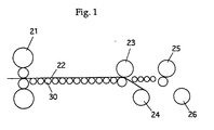
- FIG. 1 is a schematic diagram showing a conventional take-up equipment.
- a single slab has been batch-rolled to produce a single coil.
- a strip 22 leaving a last stand 21 of a finish rolling mill travels on table rollers 30 to be taken up by a take-up equipment constituted by pinch rolls 23, 25, and down coilers 24, 26 so as to be finished as a coiled product.
- the two pinch rolls 23, 25 and the two down coilers 24, 26 alternately take up the strip.
- the take-up equipment described above has been unable to handle divided materials that are taken up by dividing the strips at the exit side of a finish rolling mill or to take up an endless rolled material.
- the present invention has been made with a view toward solving the problem described above. It is an object of the present invention to provide a equipment and a method for taking up a hot-rolled material that make it possible to divide an uncut strip which has been rolled to a predetermined thickness at the exit side of a finish rolling mill and to take up the cut strips by a down coiler into a coiled product in taking up split materials or in taking up divided materials or in the endless hot rolling wherein a plurality of strips are joined and rolled. It is another object of the present invention to provide a equipment and a method for taking up a hot-rolled material that permit a thin strip running fast to be taken up in a stable manner.
- a equipment for taking up hot-rolled material the equipment being equipped with: a plurality of take-up machines (24, 26, K 1 , K 2 ) disposed at the downstream side of a hot finish rolling mill; a shearing machine (27, 2) provided on the upstream side of a pinch roll (23, 4) of the take-up machines (24, K 1 ) at the uppermost stream end; and a strip passing device (28, 6a) provided between the shearing machine and the pinch roll at the uppermost stream to prevent a strip from rising.
- a pinch roll (1) is provided at the entrance side end of the shearing machine (2), and strip passing devices (82, 83) for preventing a strip from rising are provided between the pinch roll (1) and the shearing machine (2). Further, a strip passing device (29, 6b) for preventing a strip from rising is also provided between the plurality of take-up machines.
- a pinch roll (3) is provided near the exit side of the shearing machine (2) and a strip passing device (84) for preventing a strip from rising is provided between the pinch roll and the shearing machine.
- the upper pinch rolls of the foregoing pinch rolls (23, 25, 1, 3, 4, 5) are adapted so that they can be moved toward or away from the lower ones by hydraulic cylinders.
- the strip passing devices (28, 29, 82, 83, 84) are guiding devices for restricting the rising height of a strip.
- the strip passing devices (28, 29, 6a, 6b) are airflow suction type strip passing devices that draw in a strip under suction using airflow.
- the constitution of the present invention described above can be applied also to a case where several coils are produced from a single strip or a case where a plurality of strips are joined arid rolled in the endless hot rolling in which the joined strip that has been rolled to a predetermined thickness at the exit side of a finish rolling mill is cut by a shearing machine provided on the upstream side of the pinch roll of a down coiler at the uppermost stream end, then the cut strips are taken up by a plurality of down coilers provided at the downstream side of the hot finish rolling mill thereby to produce coiled products.
- the plurality of take-up machines (K 1 , K 2 ) are down coilers.
- a pinch roll (4) disposed on the entrance side of the coiler (K 1 ) other than the down coilers at the lowermost stream end of a line is equipped with a changing means for altering the advancing direction of a strip.
- the plurality of take-up machines have carousel type reels, each having two take-up drums (66a, 66b).
- the take-up drum (66a) located at the lowermost downstream of a pass line P is provided with a wrapper roll (67) while the other take-up drum (66b) located off the pass line P is provided with a snubber roll (68) which holds a trailing end.
- a swing type strip passing device (69) for drawing a strip in under suction using airflow is disposed between the other take-up drum (66b) and a pinch roll (64) positioned on the pass line P, and a strip trailing end guide (70) is provided between the downstream end of the strip passing device and the other take-up drum (66b).
- only the strip passing devices (6a, 6b) disposed immediately before the entrance sides of the respective take-up machines employ the airflow suction type strip passing devices that draw a strip in under suction using airflow.
- Strip passing guides (82, 83, 84, 85, 86a, 86b, 87, 88a, 88b) for guiding a strip along the pass line are provided above the pass line at the positions corresponding to the points between the pinch rolls (4, 5) disposed at the entrance sides of the take-up machines (K 1 , K 2 ) and the airflow suction type strip passing devices (6a, 6b) disposed immediately before the entrance side thereof, between the airflow suction type strip passing device (6a) and the pinch roll (3) disposed immediately before the entrance side thereof, and between the shearing machine (2) and the pinch rolls (1, 3) disposed at the exit side and entrance side thereof, respectively.
- the Strip passing guides (86a, 86b, 88a, 88b) provided between the pinch rolls (4, 5) disposed at the entrance sides of the take-up machines (K 1 , K 2 ) and the airflow suction type strip passing devices (6a, 6b) disposed immediately before the entrance sides thereof are constituted by pinch roll introducing guides (86a, 88a) provided very closely to the pinch rolls (4, 5) and top guides (86b, 88b) separate therefrom.
- the top guides are placed in a position between the airflow suction type strip passing devices and the pass line to guide the leading end of a strip to the pinch roll introducing guides.
- the top guides are retracted to the position between the airflow suction type strip passing devices and the pinch rolls or to the position away from the pass line.
- the strip passing devices (86a, 86b, 88a, 88b) at the entrance sides of the pinch rolls at the upstream of the take-up machine are composed of the pinch roll introducing guides (86a, 88a) located very closely to the pinch rolls and the top guides (86b, 88b) which are separate therefrom; the trailing ends of the top guides are placed at a higher level above the pass line than the pinch roll introducing guides until the leading end of a strip is wound onto a take-up machine, then when the leading end has been wound onto the take-up machine, the trailing ends of the top guides are moved down to substantially the same level as the pinch roll introducing guides from the pass line to take up the strip.
- the winding roll of the take-up machine described above has a guide that substantially runs along the outer periphery of the coil wound around a mandrel.
- the guide presses the winding roll against the outer periphery of the coil in order to hold the trailing end of the strip.
- the airflow suction type strip passing devices (6a, 6b) are held away from the pass line; among the strip passing guides (86a, 86b, 88a, 88b) immediately before the pinch rolls at the entrance sides of the take-up machines, at least the one for taking up the article to be wound provides guide to the pinch rolls, while the remaining strip passing guides are set at a high position above the pass line; after the leading end has been wound onto the take-up machine, at least the airflow suction type strip passing devices and the strip passing guides located on the upstream side from the pinch rolls disposed at the entrance side of the take-up machine which takes up the strip next are moved down dose to the pass line to a predetermined height; and after cutting by the shearing machine, the strip can be supported under suction by the airflow suction type strip passing devices until the leading end of the following material reaches the take-up machine.
- FIG. 2 is a general block diagram showing a first embodiment of a take-up equipment in accordance with the present invention.
- a shearing machine 27 or a cutter for cutting a strip 22 or a rolled thin plate is installed between a last stand 21 of a finish rolling mill and a pinch roll 23 at the entrance side of a first down coiler 24, and a strip passing device 28 for preventing the strip 22 from rising is provided, on the exit side of the shearing machine 27, between the shearing machine 27 and the first pinch roll 23 so that it is opposed to table rollers 30.
- another strip passing device 29 is provided between the first pinch roll 23 and a second pinch roll 25.
- the strip is divided at the exit side of the finish rolling mill so that the strip made from a heavy slab is split into several lighter coils for easier handling.
- a plurality of strips are spliced by connecting the trailing end of a preceding strip with the leading end of a following strip at the entrance side of the finish rolling mill (not shown) so as to perform continuous rolling.
- One of the objects to splicing and rolling the strips in hot rolling is to ensure stabilized rolling operation of thin strips having a finished thickness of approximately 1 mm.
- the lower rigidity of thin strips makes it difficult to smoothly pass them through a rolling mill; the thin strips tend to meander because they lose tension at the moment the trailing ends thereof leave the rolling mill on the upstream side.
- the meander causes the strip to be caught up in a double layer in the rolling mill, leading to a danger of scratching a roll with resultant interruption of the rolling operation.
- the aforesaid problems can be prevented by using the strips having a thickness suited to rolling for the first and last strips and splicing a plurality of thin strips that are less suited to the rolling between them for carrying out continuous rolling.
- the strip has to be cut one by one upon the completion of the rolling and wound into coils.
- the shearing machine 27 is installed at the entrance side of the first pinch roll 23 on the exit side of the finish rolling mill.
- the strip 22 is cut into the separate strips by the shearing machine 27 and the strips are alternately taken up by two down coilers 24 and 26 in this example as illustrated in Fig. 2.
- a concern in this case is how smoothly the thin strip 22 resulting from the cutting by the shearing machine 27 runs alone before reaching the first pinch roll 23 and how smoothly it runs alone before further reaching the second pinch roll 25. More specifically, since the strip having lower rigidity runs at high speed, there is the danger that the leading end thereof rises and fails to catch the pinch rolls 23 or 25, or the low rigidity causes an insufficient carrying force of the table rollers 30 and the pinch roll 23 to be transmitted to the strip 22, preventing the strip 22 from being carried. To prevent this problem, according to the present invention, the strip passing devices 28 and 29 for preventing the strip 22 from rising are provided between the shearing machine 27 and the pinch roll 23 on the uppermost upstream side and between the pinch rolls 23 and 25 of the down coiler, respectively.
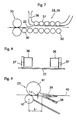
- Figure 3 is a schematic representation of the rise of a strip. As shown in this drawing, if the leading end of the strip 22 running on the table rollers 30 bumps against the table rollers 30 and rises, then the strip 22 continues running with the leading end up in some cases when the wind pressure, the weight of the rising strip 22, and the bending force are balanced. Especially when running the thin strip 22 at high speed, the weight of the strip and the bending force are reduced, making the leading end more likely to rise.
- Figure 4 shows a first embodiment of the strip passing device.
- a guiding device 31 shown in Fig. 4 provides a possible choice as the strip passing devices 28 and 29 for preventing the leading end of the strip 22 from rising; it is a plate that is installed above the top surface of the strip 22 so that it is opposed to the table rollers 30 to restrict the rising height of the strip 22.
- the elevation angle ⁇ is controlled to a minimum. As a result, lift F is minimized, eliminating the chance of the leading end of the strip 22 being kept up.
- Figure 5 shows a second embodiment of the strip passing device; and Fig. 6 is a breadthwise sectional view thereof.
- the strip passing devices 28 and 29 are installed above the top surface of the strip 22 so that they face against the table rollers 30.
- the strip passing devices 28 and 29 are respectively provided with a pair of nozzles 34 which are shaped like slits in a bottom surface 32 and which extend widthwise and outward from the interior of an air header 33; high-speed air jet is emitted through the nozzles.
- the air between the surface of the guide 31 and the strip 22 is caught by the high-speed airflows emitted in the opposite directions from each other and emitted, causing the pressure in that area to become lower than the atmospheric pressure.
- the strip 22 rises toward the strip passing device due to the suction force shown in the pressure diagram at the lower part of Fig. 6 according to the pressure difference between the atmospheric pressure acting onto the bottom surface of the strip 22 and the top surface thereof facing the strip passing device.
- Positively holding the thin strip 22 under suction makes the strip 22 nearly flat along the surface of the guide 31; therefore, the rigidity thereof in the direction of rolling line, enabling the carrying force of a pinch roll 35 and the like on the upstream to be adequately transmitted to the strip 22. This makes it possible to successfully run the thin strip at high speed.
- Figure 7 shows a third embodiment of the strip passing device; and Figure 8 is a breadthwise sectional view of Fig. 7.
- a duct 36 is provided above the top surface of the strip 22 in the direction in which the strip 22 advances, so that it is opposed to the table rollers 30.
- a plurality of the ducts 36 are provided widthwise (in two trains in this embodiment); the bottom surfaces thereof facing the strip 22 are open.
- the strip 22 rise by being drawn up to the ducts 36 because of the difference in the pressure on the top and bottom surfaces of the strip.
- the strip 22 that has been drawn up is pressed against wheels 37 attached to the ducts 36 and fed out by the pinch roll 35 located on the upstream side.
- the rigidity of the thin strip 22 in the rolling line direction is enhanced by positively holding it under suction so as to enable the carrying force of the upstream pinch roll 35 to be transmitted to the strip 22.
- Figure 9 shows the layout of a gate 38 on the exit side of the pinch roll 23 in the endless rolling wherein the strip is divided into coils.
- the position of the gate 38 on the exit side of the endless rolling is indicated by the solid line in the drawing; the distal end of the gate is lower than a pass line 40 by L2, which is different with the position of the gate 39 in batch rolling indicated by the dashed line.
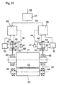
- FIG 10 shows an embodiment of a hydraulic pinch roll adapted to solve the inconvenience described above.
- the upper pinch roll 41 is supported by hydraulic cylinders 45.
- the upper pinch roll 41 and the lower pinch roll 42 are rotatably mounted on upper chocks 43 (bearings) and lower chocks 44 (bearings) provided in a housing (not shown).
- the strip 22 is damped between the upper and lower pinch rolls 41 and 42 so that its advancing direction is changed downward at an angle and it is led by the down coilers 24 and 26 to be taken up.
- the hydraulic cylinders 45 are disposed on the right and left bearings of the upper pinch roll 41 and connected to servo valves 47 via pipes 46.
- the lift of the servo valves 47 is controlled by a command signal 48 to regulate the amount of incoming and outgoing hydraulic oil into the cylinders 45.
- the command signal 48 is generated by a controller 49, namely, a pinch roll controller; it controls the servo valves 47 so that the position and pressing force of the upper pinch roll 41 coincide with set values.
- the pinch roll controller 49 receives a setting signal 50 from a setter 57 to produce the command signal for the servo valves 47; it receives a sequence signal 58 from a higher-order controller or a processing computer, not shown, as the strip 22 moves forward so as to adjust the gap of the pinch roll or change the pressing force.
- a pressing force detector 60 are composed of pressure detectors 51 and 52 for detecting the pressures on the head side and the rod side of the hydraulic cylinders 45; it calculates pressing force F of a hydraulic pinch roll 61 from the signals received from the pressure detectors 51 and 52 by using a computing device 53.
- a position detector 54 detects the positions of pistons 55 of the hydraulic cylinders 45.
- load cells for directly detecting the pressing force of the pinch roll 61 may be provided on the bearings 44 of the lower pinch roll 42.
- Figure 11 shows the comparison of the jumping amount of the upper pinch roll 41 in the conventional air pinch roll adapted to hold the upper pinch roll 41 by air cylinders and the jumping amount of the upper pinch roll 41 in the hydraulic pinch roll 61 adapted to hold the upper pinch roll 41 by the hydraulic cylinders 45 in accordance with the present invention.
- the upper pinch roll 41 jumps 42.2 mm at maximum, which is 16 times the thickness and it takes a long time to come back to the position to hold the strip 22.
- the upper pinch roll 41 jumps only 19.4 mm at maximum and quickly comes back to the position to hold the strip 22.
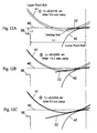
- Figures 12A, 12B, and 12C show the trajectories of the leading end of the strip 22 versus the movement of the upper pinch roll 41.
- the distal end of the gate 38 on the exit side is located L1 away from the center of the pinch roll 42 and lower than the pass line 40 by L2 at maximum. Hence, the moment the leading end of the strip 22 goes down L2 or more by being pressed by the upper pinch roll 41 while it advances a distance of L1, the strip 22 is guided toward the down coiler 24 and it does not miss the gate 38.
- the jumps of the upper pinch roll 41 at points t1, t2, and t3 of Fig. 11 are 19.4 mm, 13.5 mm, and 5.5 mm, respectively: the trajectories of the leading end of the strip 22 passing through the roll gap formed by the positional relationship of the upper and lower pinch rolls 41 and 42 at the foregoing points are shown in Fig. 12. Since the jumped upper pinch roll 41 of the hydraulic pinch roll 61 comes back quickly, the leading end of the strip 22 already reaches L2 or lower than the pass line 40 at point t3 of of Fig. 12C; therefore, the leading end of the strip 22 does not run over or miss the gate 38 on the exit side.
- the hydraulic rigid spring makes the upper pinch roll 41 quickly come back even when it jumps, providing a great advantage in that the stable guide of the leading end of the strip 22 can be achieved in comparison with the air cylinder type. This advantage has been confirmed with an actual machine.
- the constitution described above makes it possible to cut a spliced strip which has been rolled to a predetermined thickness into a plurality of strips at the exit side of the finish rolling mill by the shearing machine installed at the exit side of the finish rolling mill and to feed them to the hydraulic pinch rolls in a stable manner by using the strip passing devices, then further led to the down coilers in a stable manner by the hydraulic pinch rolls.
- a thin strip having a thickness of about 1 mm can be turned into coils of strips, which was impossible in the past.
- the take-up equipment in accordance with the present invention is provided with the shearing machine at the exit side of the finish rolling mill, so that it is capable of cutting a plurality of joined strips, which have been rolled to a predetermined thickness, into separate strips at the exit side of the finish rolling mill.
- the strip passing devices are provided between the shearing machine and the pinch roll and between the pinch roll and the pinch roll of the following down coiler so as to ensure stable feed of even a strip as thin as approximately 1 mm to the pinch rolls by preventing the leading end of the strip from rising.
- the use of the hydraulic pinch rolls enables stable guide of the strip to the down coiler, making it possible to produce a coil of thin strip having a thickness of about 1 mm, which has been impossible in the conventional hot rolling process.
- Figure 13 is a general block diagram showing a second embodiment of the take-up equipment in accordance with the present invention.
- Figure 13 shows the downstream side of a finish rolling mill which continuously performs finish rolling a joined sheet bar in a continuous hot rolling line: a pinch roll 1 on the entrance side of the shearing machine, a rotary shearing machine 2, a pinch roll 3 on the exit side of the shearing machine, a pinch roll 4 for No. 1 coiler K 1 , and a pinch roil 5 for No. 2 coiler K 2 are disposed from the upstream side along pass line P.
- the No. 1 coiler K 1 and the No. 2 coiler K 2 are disposed in series along the line from the upstream side.
- a lower roll 4a of the pinch roll 4 is configured so that it can be moved in parallel to the pass line by a hydraulic cylinder or the like.
- the hydraulic cylinder 45 shown in Fig 10 the upper pinch roll is pulled upward and the lower roll 4a is moved in parallel to the pass line.
- the moving mechanism for the lower roll 4a corresponds to the changing means in the present invention.
- strip passing devices 6 (6a, 6b) Disposed at the entrance side of the pinch rolls 4 and 5 are strip passing devices 6 (6a, 6b) as shown in Fig. 14.
- the respective strip passing devices 6a and 6b are placed at 10 to 50 mm above pass line P as indicated by the solid lines in Fig. 13 when they are in use, while they are placed away from pass line P as indicated by the two-dot chain line in Fig. 13 when they are not in use.
- Figure 14 shows basically the same constitution as that shown in Fig. 6 except that it illustrates the constitution based more on an actual machine; it is a breadthwise sectional view of the strip passing device 6 in operation, reference character T denoting a table roller T guiding the bottom surface of strip S.
- the strip passing device 6 is composed of a chamber 61 having a predetermined capacity and a guiding member 62 covering the entire surface of the chamber 61.
- a gas supply channel 71 is connected to the top of the chamber 61; the gas supply channel 71 is connected to a gas supply source 73 via a flow rate regulating valve 72.
- the guiding member 62 has a plurality of nozzle bores 62a and 62b formed vertically at angles along pass line P at predetermined intervals.
- the nozzle bores 62a and 62b are shaped so that they spread downward from the center of the width of the guiding member 62 toward both ends of the width.
- the bottom surface of the guiding member 62 is formed into a plane which provides a guiding surface 62c opposed to the top surface of strip S.
- the heights at which the strip passing guides are positioned above pass line P until the leading end (the first leading end that is not the edge cut by the shearing machine 2) of a continuously hot-rolled strip out from the finish rolling mill is first wound onto a coiler, namely, the No. 1 coiler K 1 in this embodiment, are different from the heights at which they are positioned after that; the positions thereof in these two cases are shown by solid lines and two-dot chain lines in Fig. 13.
- the strip passing guides located between the strip passing device 6 (6a, 6b) and the pinch rolls 4, 5 are constituted by the pinch roll introducing guide 86a (88a) provided near the pinch rolls and a separate top guide 86b (88b).
- the top guide 86b (88b) is positioned between the strip passing device 6 and pass line P when the strip passing device 6 has been retracted from pass line P (see Fig. 15A), and strip S is guided to the pinch roll introducing guide 86a (88a); while it is positioned between the strip passing device 6 and the pinch roll 4 (5) when the strip passing device 6 has been set in the vicinity of pass line P to be ready for operation (see Fig. 15B).
- the top guide 86b turns around a predetermined center of rotation to switch from the state illustrated in Fig. 15A to that illustrated in Fig. 15B.
- This feature of the top guide 86b allows distance L between the center of the pinch roll 4 and the strip passing device 6a can be reduced when the strip passing device is in operation as shown in Fig. 15B.
- bringing the strip passing device very closely to the entrance side of the pinch roll ensures smooth introduction of strip S from the strip passing device to the pinch roll.
- FIG. 15 denotes a member that prevents strip S from interfering with downstream table rollers T when it moves from the pinch roll 4 to No.1 coiler K 1 .
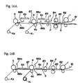
- Figure 16A shows the layout of the respective constituent units above pass line P until the first leading end of a strip reaches No. 1 coiler K 1 when taking up a first coil by No. 1 coiler K 1
- Fig. 16B shows the same when the first cutting is performed by the shearing machine 2.
- the upper rolls of the pinch rolls 1 and 3 and the upper drum of the shearing machine 2 are raised sufficiently high to avoid contact with strip S, and all strip passing guides 81 through 85 are also raised to die bottom edges of the upper rolls.
- the strip passing guide 81 has the upstream-side distal end shaped to curled outward so as to enable the leading end of strip S, which has left the finish rolling mill, to be smoothly introduced between the upper roll and the lower roll of the pinch roll 1.
- the top guides 86b, and 88b are turned to be placed between the strip passing devices 6a, 6b and the pinch rolls 4, 5.
- the strip passing devices 6a and 6b are positioned at 10 to 50 mm above pass line P; however, no gas is introduced into the chambers.
- the strip passing guide87, the pinch roll introducing guides 86a, 88a, and the strip passing guides 81 through 85 are positioned substantially parallel to pass line P at 10 to 50 mm above pass line P.
- the strip passing guide 84 is shaped so that the exit side relative to the shearing machine 2 opens at an angle; this angle is set smaller than that shown in Fig. 16A.
- the lower roll 4a of the pinch roll 4 is moved to a position where the center thereof matches that of the upper roll or toward the downstream side therefrom.
- the upper rolls of the pinch rolls 1 and 3 are moved down to predetermined positions.
- strip S can be carried from the pinch roll 1 to the pinch roll 4 while the gap relative to pass line P being restricted to 10 to 50 mm by the strip passing guides 81 through 85, the guiding surface 62c of the strip passing device 6a, and the pinch roll introducing guide 86a, thus enabling strip S to be passed at high speed in a stable fashion.
- the upper and lower drums are brought close to pass line P so as to set the shearing machine 2 ready for cutting according to a cutting timing as illustrated in Fig. 16B, and the introduction of gas into the chambers of the strip passing devices 6a and 6b is begun.
- the trailing end of the preceding strip is supported under suction by the strip passing device 6a, causing the apparent rigidity of strip S to be increased; therefore, the strip can be wound on No. 1 coiler K 1 in a stable manner.
- the strip passing devices 6a and 6b since the leading end of the following strip is supported under suction by the strip passing devices 6a and 6b, causing the apparent rigidity of strip S to be increased; therefore, the strip can be passed at high speed and wound on the coiler K 2 in a stable manner.
- the pinch roll 1 holds strip S on the following strip side at the time of cutting by the shearing machine 2, the following strip is prevented from springing back toward the finish rolling mill after cutting.
- the pinch roll 3 smoothes out the wavy leading end of the following strip to allow smooth introduction to the pinch roll 4.
- the space above pass line P is limited to 10 to 50 mm by the strip passing guides 82 through 85 and 87, and the pinch roll introducing guides 86a and 88a, minimizing the chance of puckering caused by the wavy motion of strip S when it runs at high speed.
- the installation of the strip passing guides 85 and 87 enables strip S, which has the propelling force imparted by the pinch rolls 3 and 4, to be smoothly introduced to the strip passing devices 6a and 6b.
- strip S finish-rolled to be thin by continuous hot rolling can be taken up while passing it at high speed in a stable manner.
- Figure 17A shows the layout of the constituent units above pass line P until the first leading end of a continuously hot-rolled strip reaches No. 2 coiler K 2 ;
- Fig. 17B shows the same when the first cutting is carried out by the shearing machine 2;
- Fig. 17C shows the same when the second cutting is carried out, when a first strip to be coiled is wound on No. 2 coiler K 2 located at the lowermost downstream.
- the layout shown in Fig. 17A is substantially the same as that shown in Fig. 16A except that the upper roll of the pinch roll 4 is positioned away from the lower roll 4a.
- the leading end of strip S leaving the finish rolling mill is restricted in its vertical flexture by the strip passing guides 81 through 85 and 87 and the pinch roll introducing guide 86a although it vertically flexes, and the leading end is introduced to the pinch roll 5 while being guided by the top guide 88b and the pinch roll introducing guide 88a and wound on the caller K 2 .
- the entire shearing machine 2 is moved down to stand by for cutting as indicated by the two-dot chain line in Fig. 17A; the remaining constituent units are moved as illustrated in Fig. 17B to wind the strip at high speed on No. 2 coiler K 2 .
- the layout of the constituent units is changed in the same manner as Fig. 16A and Fig. 16B except that the positions of the strip passing device 6b, the pinch roll introducing guide 88a, the top guide 88b, and the lower roll 4a of the pinch roll remain unchanged; thus, strip S is passed at high speed and wound on No. 2 caller K 2 in a stable fashion.
- the shearing machine 2 is set ready for cutting and the gas is introduced into the chamber of the strip passing device 6a and cutting is implemented by the shearing machine 2.
- the leading end of the following strip is supported under suction by the strip passing device 6a, causing the apparent rigidity of the following strip to be increased; therefore, the leading end of the following strip can be passed at high speed and wound on No.
- the shearing machine 2 is set in the standby mode for cutting, the strip passing device 6b is moved down to the operating position, and the two strip passing devices 6a and 6b are stopped in the positions to perform high-speed winding on No. 1 coiler K 1 as in the case illustrated in Figs. 16A and 16B.
- the shearing machine 2 is set ready for cutting and a gas is introduced into the chambers of the strip passing devices 6a and 6b to set them ready for operation as illustrated in Fig. 17C.
- This makes it possible to perform stable winding of the trailing end of the preceding strip, i.e. the second strip, on No. 1 coiler K 1 after cutting by the shearing machine 2 and the leading end of the following strip, i.e. the third strip, on No. 2 coiler K 2 as in the case shown in Figs. 16A and 16B.
- the constituent units should be set as illustrated in Fig. 16A or Fig. 17A when the trailing end has left the finish rolling mill to prevent the trailing end from being broken, causing such a problem of dogging up the constituent units.
- two coilers K 1 and K 2 are disposed in series along the line; this embodiment can be applied to a case where three or more coilers are disposed.
- the strip passing guides 81 through 85 and 87, the pinch roll introducing guides 86a, 88a, and the top guides 86b, 88b are not indispensable; however, providing those guides enable further stable high-speed passing and winding.
- the pinch roll introducing guide 86a (88a) and the top guide 86b (88b) may alternatively be made integral.
- the top guides 86b and 88b are configured so that they turn to withdraw to the position above pass line P and between the strip passing devices 6a, 6b and the pinch rolls 4, 5, respectively.
- the withdrawing position is not limited thereto; they may alternatively withdraw to a position off pass line P, for example, sideways relative to pass line P.
- the advancing direction of strip S is changed by moving only the lower roll 4a of the pinch roll 4; the changing means in the invention, however, is not limited thereto: both upper and lower rolls may alternatively be tilted together.
- thin strips can be taken up in a stable manner by passing them at high speed. This makes it possible to achieve high-speed feed at a higher yield, to secure the temperature of strips at the exit side of a finish rolling mill with resultant higher quality, and hence to secure a predetermined sales.
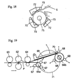
- Fig. 18 is a partial diagram showing a take-up equipment in accordance with the present invention.
- the winding roll of the take-up equipment in the drawing has guides 72 that are located substantially along the outer periphery of the coil wound around a mandrel 75.
- the guides press winding rolls 73 against the outer periphery of the coil to hold the trailing end of the strip S.
- the trailing end of strip S is held to prevent buckling caused by the flopping of the trailing end, ensuring smooth take-up operation.
- FIG 19 is a general block diagram showing a third embodiment of the take-up equipment in accordance with the present invention.
- the plurality of take-up machines have carousel type reds, each composed of two winding drums 66a and 66b.
- the two winding drums 66a and 66b revolve along the arc indicated by an arrow 71; one of them (the winding drum 66a in the drawing) is positioned at the lowermost downstream of pass line P of strip S on a hot rolling line, while the other (the winding drum 66b in the drawing) is located away from pass line P.
- a shearing machine 62 and pinch rolls 63 and 64 respectively located at the entrance side and the exit side thereof.
- the winding drum 66a located at the lowermost downstream of pass line P is provided with a wrapper roll 67 to allow strip S to be smoothly wound around the winding drum 66a.
- the other winding drum 66b located away from pass line P is provided with a snubber roll 68 for holding the trailing end of the strip so as to hold the trailing end of the wound strip to prevent it from unwinding.
- a guiding device for restricting the rising height of the strip or a swing type strip passing device 69 for drawing in the strip by an airflow is disposed between the winding drum 66b located away from pass line P and the pinch roll 64 so as to enable smooth passing of the strip from the pinch roll 64 to the winding drum 66b.
- the swing type strip passing device 69 swings away outward to avoid interfering with their trajectories.
- a strip trailing end guide 70 is provided between downstream side of the strip passing device 69 and the drum on the coil ejecting side, namely, the winding drum 66b, in order to introduce the strip, which has been guided by the swing type strip passing device 69, into the gap between the winding drum 66b and the snubber roll 68.
- the rest of the constitution is the same as the constitution of the first embodiment and / or the second embodiment.
- the winding of the strip is begun by winding it onto the winding drum 66a, which is located at the lowermost downstream end of pass line P, by using the wrapper roll 67, then the winding drum is swung to the position away from pass line P to wind the strip onto the winding drum (66b in this case) in that position.
- the trailing end of the strip is held by the snubber roll 68 to prevent it from unwinding, and the strip is carried out or issued; at the same time, the winding of the next strip is begun by the winding drum 66a located at the lowermost downstream end, thus permitting high-speed winding of strips.
Landscapes
- Engineering & Computer Science (AREA)
- Mechanical Engineering (AREA)
- Winding, Rewinding, Material Storage Devices (AREA)
- Metal Rolling (AREA)
Abstract
Description
The method for taking up the continuously hot-rolled strip by the equipment will now be described.
Figure 16A shows the layout of the respective constituent units above pass line P until the first leading end of a strip reaches No. 1 coiler K1 when taking up a first coil by No. 1 coiler K1, and Fig. 16B shows the same when the first cutting is performed by the shearing
Claims (18)
- A take-up equipment for a hot-rolled material, comprising: a plurality of take-up machines (24, 26, K1, K2) disposed at the downstream side of a hot finish rolling mill; a shearing machine (27, 2) provided on the upstream side of a pinch roll (23, 4) of said take-up machines (24, K1) at the uppermost stream end; and a strip passing device (28, 6a) provided between said shearing machine and the pinch roll at the uppermost stream to prevent a strip from rising.
- A take-up equipment according to Claim 1, wherein a pinch roll (1) is provided at the entrance side end of said shearing machine (2).
- A take-up equipment according to Claim 2, wherein strip passing devices (82, 83) for preventing a strip from rising are provided between said pinch roll (1) on the entrance side of said shearing machine and said shearing machine (2).
- A take-up equipment according to any one of Claims 1 to 3, wherein a strip passing device (29, 6b) for preventing a strip from rising is provided between the pinch rolls of said plurality of take-up machines.
- A take-up equipment according to any one of Claims 1 to 4, wherein a pinch roll (3) is provided near the exit side of said shearing machine (2) and a strip passing device (84) for preventing a strip from rising is provided between said pinch roll and said shearing machine.
- A take-up equipment according to any one of Claims 1 to 5, wherein the upper pinch rolls of said pinch rolls (23, 25, 1, 3, 4, 5) are adapted so that they can be moved toward or away from the lower ones by hydraulic cylinders.
- A take-up equipment according to any one of Claims 1 to 6, wherein said strip passing devices (28, 29, 82, 83, 84) are guiding devices for restricting the rising height of a strip.
- A take-up equipment according to any one of Claims 1 to 6, wherein said strip passing devices (28, 29, 6a, 6b) are airflow suction type strip passing devices that draw in a strip under suction using airflow.
- A take-up equipment according to any one of Claims 1 to 8, wherein said plurality of take-up machines (K1, K2) are down coilers.
- A take-up equipment according to Claim 9, wherein a pinch roll (4) disposed on the entrance side of said coiler (K1) other than the down coiler at the lowermost stream end of a line is equipped with a changing means for changing the advancing direction of a strip.
- A take-up equipment according to any one of Claims 1 to 8, wherein said plurality of take-up machines have carousel type reels having two take-up drums (66a, 66b).
- A take-up equipment according Claim 11, wherein: one take-up drum (66a) located at the lowermost downstream of a pass line P is provided with a wrapper roll (67) while the other take-up drum (66b) located off said pass line P is provided with a snubber roll (68) which holds a trailing end; a swing type strip passing device (69) for drawing a strip in under suction using airflow is disposed between said other take-up drum (66b) and a pinch roll (64) positioned on said pass line P; and a strip trailing end guide (70) is provided between the downstream end of said strip passing device and said other take-up drum (66b).
- A take-up equipment according to Claim 9, wherein only said strip passing devices (6a, 6b) disposed immediately before the entrance sides of said respective take-up machines employ the airflow suction type strip passing devices that draw a strip in under suction using airflow.
- A take-up equipment for continuous hot rolling according to Claim 13, wherein: strip passing guides (82, 83, 84, 85, 86a, 86b, 87, 88a, 88b) for guiding a strip along the pass line are provided above said pass line at the positions corresponding to the points between said pinch rolls (4, 5) disposed at the entrance sides of said take-up machines (K1, K2) and said airflow suction type strip passing devices (6a, 6b) disposed immediately before the entrance side thereof, between said airflow suction type strip passing device (6a) and said pinch roll (3) disposed immediately before said entrance side thereof, between said airflow suction type strip passing device (6b) on downstream side and an upstream pinch roll thereof, and between said shearing machine (2) and said pinch rolls (1, 3) disposed at the exit side and entrance side thereof, respectively.
- A take-up equipment for continuous hot rolling according to Claim 14, wherein: said strip passing guides (86a, 86b, 88a, 88b) provided between said pinch rolls (4, 5) disposed at the entrance sides of said take-up machines (K1, K2) and said airflow suction type strip passing devices (6a, 6b) disposed immediately before the entrance sides thereof are constituted by pinch roll introducing guides (86a, 88a) provided very closely to the pinch rolls (4, 5) and top guides (86b, 88b) separate therefrom; and when said airflow suction type strip passing devices are retracted from said pass line, said top guides are placed in a position between said airflow suction type strip passing devices and said pass line to guide said leading end of a strip to said pinch roll introducing guides; and when said airflow suction type strip passing devices are rested in the vicinity of said pass line where they are put in operation, said top guides are retracted to the position between said airflow suction type strip passing devices and said pinch rolls or to the position away from said pass line.
- A method for taking up a hot-rolled material wherein: strip passing devices (86a, 86b, 88a, 88b) at the entrance sides of pinch rolls at the upstream of a take-up machine are composed of the pinch roll introducing guides (86a, 88a) located very closely to the pinch rolls and the top guides (86b, 88b) which are separate therefrom; the trailing ends of said top guides are placed at a higher level above a pass line than said pinch roll introducing guides until the leading end of a strip is wound onto said take-up machine, then when the leading end has been wound onto said take-up machine, the trailing ends of said top guides are moved down to substantially the same level as said pinch roll introducing guides from said pass line to take up said strip.
- A take-up method according to Claim 16, wherein a winding roll of said take-up machine described above has a guide that substantially runs along the outer periphery of a coil wound around a mandrel, and when a strip has been wound up around said mandrel, said guide presses said winding roll against the outer periphery of said coil in order to hold the trailing end of said strip.
- A take-up method for a continuously hot-rolled strip by a take-up equipment for continuous hot rolling according to Claim 16 or 17, wherein: until the first leading end of a strip reaches said take-up machine, said airflow suction type strip passing devices (6a, 6b) are held away from said pass line; among said strip passing guides (86a, 86b, 88a, 88b) immediately before said pinch rolls at the entrance sides of said take-up machines, at least the one for taking up the article to be wound provides guide to said pinch rolls, while the remaining strip passing guides are set at a high position above said pass line; after the leading end has been wound onto said take-up machine, at least said airflow suction type strip passing devices and said strip passing guides located on the upstream side from said pinch rolls disposed at the entrance side of said take-up machine which takes up the strip next are moved down dose to said pass line to a predetermined height; and after cutting by said shearing machine, said strip can be supported under suction by said airflow suction type strip passing devices until the leading end of the following material reaches said take-up machine.
Applications Claiming Priority (3)
| Application Number | Priority Date | Filing Date | Title |
|---|---|---|---|
| JP30874397 | 1997-11-11 | ||
| JP30874397A JP3929147B2 (en) | 1997-11-11 | 1997-11-11 | Winding equipment |
| PCT/JP1998/001187 WO1999024187A1 (en) | 1997-11-11 | 1998-03-19 | Hot rolled material take-up equipment and take-up method |
Publications (2)
| Publication Number | Publication Date |
|---|---|
| EP1016471A1 true EP1016471A1 (en) | 2000-07-05 |
| EP1016471A4 EP1016471A4 (en) | 2006-05-31 |
Family
ID=17984759
Family Applications (1)
| Application Number | Title | Priority Date | Filing Date |
|---|---|---|---|
| EP98909767A Withdrawn EP1016471A4 (en) | 1997-11-11 | 1998-03-19 | EQUIPMENT FOR RECEIVING HOT ROLLED MATERIALS AND RECEPTION METHOD |
Country Status (12)
| Country | Link |
|---|---|
| US (1) | US6185971B1 (en) |
| EP (1) | EP1016471A4 (en) |
| JP (1) | JP3929147B2 (en) |
| KR (1) | KR100583864B1 (en) |
| CN (1) | CN1121284C (en) |
| AU (1) | AU734852B2 (en) |
| BR (1) | BR9806099A (en) |
| CA (1) | CA2251028C (en) |
| NZ (1) | NZ332579A (en) |
| TR (1) | TR199802145T1 (en) |
| TW (1) | TW393352B (en) |
| WO (1) | WO1999024187A1 (en) |
Cited By (4)
| Publication number | Priority date | Publication date | Assignee | Title |
|---|---|---|---|---|
| EP1285703A1 (en) * | 2000-02-24 | 2003-02-26 | Ishikawajima-Harima Heavy Industries Co., Ltd. | Control method of hydaulic pinch roll and control unit thereof |
| CN102553974A (en) * | 2011-12-28 | 2012-07-11 | 河北省首钢迁安钢铁有限责任公司 | Method for improving leveling quality of thin gauge strip steel |
| EP2881185A1 (en) | 2013-12-05 | 2015-06-10 | SMS Siemag AG | Method and device for producing a metallic strip in casting and rolling |
| WO2016162147A1 (en) * | 2015-04-10 | 2016-10-13 | Primetals Technologies Limited | Foil coiling system and method |
Families Citing this family (22)
| Publication number | Priority date | Publication date | Assignee | Title |
|---|---|---|---|---|
| JP4618878B2 (en) * | 2000-12-21 | 2011-01-26 | 大和製罐株式会社 | Metal winding device |
| DE60201664T2 (en) * | 2001-02-22 | 2005-11-10 | Alcan International Ltd., Montreal | METHOD FOR ROLLING ALUMINUM FOIL |
| RU2208484C2 (en) * | 2001-04-12 | 2003-07-20 | Открытое акционерное общество "Новолипецкий металлургический комбинат" | Method for making rolled strips |
| DE10208964A1 (en) * | 2002-02-28 | 2003-09-18 | Sms Demag Ag | Deflection device for a belt in a reel system |
| ITRM20070233A1 (en) * | 2007-04-20 | 2008-10-21 | Danieli Off Mecc | GUIDE SYSTEM FOR A METAL TAPE OUTPUT FROM A MILL |
| KR101035506B1 (en) * | 2008-09-25 | 2011-05-20 | 현대제철 주식회사 | Pinch Roller Device |
| US20100242559A1 (en) * | 2009-03-24 | 2010-09-30 | Saenz De Miera Vicente Martin | Method of producing aluminum products |
| CN102205360B (en) * | 2011-03-14 | 2013-03-13 | 江苏恒力组合机床有限公司 | Pneumatic self-locking type automatic lifting take-up device for water-tank wire drawing machine |
| CN102189151B (en) * | 2011-03-22 | 2013-04-10 | 无锡亚新通用机械有限公司 | Clutch |
| CN102847749A (en) * | 2011-06-29 | 2013-01-02 | 鞍钢股份有限公司 | Method for positioning jaw of winding drum of coiler |
| JP6171532B2 (en) * | 2012-04-27 | 2017-08-02 | 新日鐵住金株式会社 | Guide plate device for hot rolling line |
| CN104307927B (en) * | 2014-11-13 | 2016-06-29 | 武汉钢铁(集团)公司 | Eliminate hot rolling thin strip and be wound around the control method of coiler pinch-roll |
| CN104815872B (en) * | 2015-04-01 | 2017-06-20 | 中冶陕压重工设备有限公司 | A kind of active threading guide plate |
| CN107030109B (en) * | 2017-06-16 | 2018-12-14 | 江苏国铝高科铝业有限公司 | A kind of single reversing hot mill with coilers located on each side of the mill cold burden band load test run method |
| KR102014465B1 (en) * | 2018-09-19 | 2019-11-04 | 김진묵 | Strip supply equipment for in vitro diagnostic kit assembly |
| CN109834113B (en) * | 2019-03-25 | 2024-04-26 | 中冶南方工程技术有限公司 | Lead processing equipment in coil preparation station |
| JP7290139B2 (en) * | 2020-07-01 | 2023-06-13 | Jfeスチール株式会社 | Steel strip winding method and winding equipment |
| CN112453065B (en) * | 2020-10-14 | 2023-03-21 | 首钢京唐钢铁联合有限责任公司 | Coiling control method and device |
| CN113245380B (en) * | 2021-04-16 | 2023-04-11 | 首钢集团有限公司 | Method for preventing strip steel from piling and related equipment |
| CN115465705B (en) * | 2022-09-23 | 2026-02-17 | 山信软件股份有限公司 | A collision avoidance device and method for a strip positioning correction device |
| CN116550756A (en) * | 2023-05-10 | 2023-08-08 | 首钢京唐钢铁联合有限责任公司 | A strip steel coiling method, control device and computer-readable storage medium |
| KR20240165724A (en) | 2023-05-16 | 2024-11-25 | 주식회사 포스코 | Surface treatment apparatus and surface treatment method |
Family Cites Families (9)
| Publication number | Priority date | Publication date | Assignee | Title |
|---|---|---|---|---|
| US4002047A (en) * | 1975-07-07 | 1977-01-11 | Baldwin-Gegenheimer Corporation | Sheet material decurling apparatus |
| DE3517090A1 (en) * | 1985-05-11 | 1986-11-13 | SMS Schloemann-Siemag AG, 4000 Düsseldorf | METHOD FOR ROLLING FROM ROOF TO WARM BROADBAND |
| JPH04200802A (en) * | 1990-11-29 | 1992-07-21 | Hitachi Ltd | Method for detecting and splitting joined parts of rolled stock in continuous hot rolling equipment |
| US5560236A (en) * | 1993-10-07 | 1996-10-01 | Kawasaki Steel Corporation | Method of rolling and cutting endless hot-rolled steel strip |
| JP2981092B2 (en) * | 1993-11-02 | 1999-11-22 | 石川島播磨重工業株式会社 | Rolling equipment |
| JP3386865B2 (en) * | 1993-11-02 | 2003-03-17 | 石川島播磨重工業株式会社 | Strip gap forming device |
| DE59705828D1 (en) * | 1996-02-14 | 2002-01-31 | Sms Demag Ag | Coiler line for strips |
| IT1288882B1 (en) * | 1996-04-23 | 1998-09-25 | Danieli Off Mecc | PROCEDURE FOR DRIVING THE INTERCAGE BELT IN A LAMINATION FINISHER TRAIN AND RELATED INTERCAGE DEVICE |
| JP3224740B2 (en) * | 1996-05-13 | 2001-11-05 | 三菱重工業株式会社 | Hot rolling equipment |
-
1997
- 1997-11-11 JP JP30874397A patent/JP3929147B2/en not_active Expired - Fee Related
-
1998
- 1998-03-19 EP EP98909767A patent/EP1016471A4/en not_active Withdrawn
- 1998-03-19 CA CA002251028A patent/CA2251028C/en not_active Expired - Fee Related
- 1998-03-19 WO PCT/JP1998/001187 patent/WO1999024187A1/en not_active Ceased
- 1998-03-19 KR KR1019980708784A patent/KR100583864B1/en not_active Expired - Lifetime
- 1998-03-19 AU AU64198/98A patent/AU734852B2/en not_active Ceased
- 1998-03-19 CN CN98801324A patent/CN1121284C/en not_active Expired - Lifetime
- 1998-03-19 TR TR1998/02145T patent/TR199802145T1/en unknown
- 1998-03-19 US US09/171,944 patent/US6185971B1/en not_active Expired - Lifetime
- 1998-03-19 BR BR9806099A patent/BR9806099A/en not_active IP Right Cessation
- 1998-03-19 NZ NZ332579A patent/NZ332579A/en not_active IP Right Cessation
- 1998-03-26 TW TW087104512A patent/TW393352B/en not_active IP Right Cessation
Cited By (6)
| Publication number | Priority date | Publication date | Assignee | Title |
|---|---|---|---|---|
| EP1285703A1 (en) * | 2000-02-24 | 2003-02-26 | Ishikawajima-Harima Heavy Industries Co., Ltd. | Control method of hydaulic pinch roll and control unit thereof |
| US6604663B2 (en) * | 2000-02-24 | 2003-08-12 | Ishikawajima-Harima Heavy Industries Co., Ltd. | Control method of hydraulic pinch roll and control unit thereof |
| CN102553974A (en) * | 2011-12-28 | 2012-07-11 | 河北省首钢迁安钢铁有限责任公司 | Method for improving leveling quality of thin gauge strip steel |
| EP2881185A1 (en) | 2013-12-05 | 2015-06-10 | SMS Siemag AG | Method and device for producing a metallic strip in casting and rolling |
| DE102014213537A1 (en) | 2013-12-05 | 2015-06-11 | Sms Siemag Ag | Method and device for producing a metallic strip in the cast rolling process |
| WO2016162147A1 (en) * | 2015-04-10 | 2016-10-13 | Primetals Technologies Limited | Foil coiling system and method |
Also Published As
| Publication number | Publication date |
|---|---|
| CN1239447A (en) | 1999-12-22 |
| CA2251028A1 (en) | 1999-05-11 |
| KR20000065164A (en) | 2000-11-06 |
| JP3929147B2 (en) | 2007-06-13 |
| JPH11147129A (en) | 1999-06-02 |
| TW393352B (en) | 2000-06-11 |
| TR199802145T1 (en) | 2001-11-21 |
| CN1121284C (en) | 2003-09-17 |
| KR100583864B1 (en) | 2006-11-30 |
| AU6419898A (en) | 1999-05-31 |
| US6185971B1 (en) | 2001-02-13 |
| BR9806099A (en) | 1999-08-24 |
| CA2251028C (en) | 2002-09-10 |
| WO1999024187A1 (en) | 1999-05-20 |
| EP1016471A4 (en) | 2006-05-31 |
| AU734852B2 (en) | 2001-06-21 |
| NZ332579A (en) | 2000-08-25 |
Similar Documents
| Publication | Publication Date | Title |
|---|---|---|
| US6185971B1 (en) | Hot rolled material take-up equipment and take-up method | |
| CA1037744A (en) | Combination pickling-rolling mill | |
| JPH1087127A (en) | Method and device to form roll by winding up travelling paper web | |
| US4123011A (en) | Coil unwind and wind-up method and apparatus therefor | |
| JP4258588B2 (en) | Hydraulic side guide control device and control method for rolled material | |
| US5966978A (en) | Reeling unit for strip | |
| JP4735769B2 (en) | Device for preventing meandering of slit strip | |
| JP7148621B2 (en) | Device for cutting material webs into individual sheets in web storage | |
| JP3275997B2 (en) | Winding equipment for continuous hot rolling and winding method using the same | |
| CN215965615U (en) | Metal belt finishing machine | |
| JP2820520B2 (en) | Switching method of winder in endless hot rolling | |
| JPH04228217A (en) | Device for switching transporting direction of hot rolled steel strip and device for coiling | |
| MXPA98010068A (en) | Hot rolled material take-up equipment and take-up method | |
| JP3845352B2 (en) | Metal band meandering winding method and metal band meandering winding device | |
| JPH08119499A (en) | Accumulation rate device | |
| JP3591409B2 (en) | Cooling apparatus for hot-rolled steel strip and cooling method | |
| JP2798024B2 (en) | Hot rolling equipment | |
| JP2000280023A (en) | Winding method of slit material and meandering prevention device | |
| JP2012091189A (en) | Device for preventing meandering of slit band plate | |
| US3707252A (en) | Automatic tensioning device for multiple line strip | |
| JP3349425B2 (en) | Plate rolling method and apparatus | |
| JP4105876B2 (en) | Continuous heat treatment equipment and continuous heat treatment method for cold-rolled sheet of grain oriented silicon steel | |
| JP2000005820A (en) | High speed hot stripping machine | |
| JP2002137003A (en) | Hot rolling method for metal sheet having uneven pattern | |
| KR20250108614A (en) | Winding method and system |
Legal Events
| Date | Code | Title | Description |
|---|---|---|---|
| PUAI | Public reference made under article 153(3) epc to a published international application that has entered the european phase |
Free format text: ORIGINAL CODE: 0009012 |
|
| 17P | Request for examination filed |
Effective date: 19991001 |
|
| AK | Designated contracting states |
Kind code of ref document: A1 Designated state(s): DE FR GB IT NL |
|
| RAP1 | Party data changed (applicant data changed or rights of an application transferred) |
Owner name: JFE STEEL CORPORATION Owner name: ISHIKAWAJIMA-HARIMA HEAVY INDUSTRIES CO., LTD. |
|
| A4 | Supplementary search report drawn up and despatched |
Effective date: 20060421 |
|
| RAP1 | Party data changed (applicant data changed or rights of an application transferred) |
Owner name: JFE STEEL CORPORATION Owner name: IHI CORPORATION |
|
| 17Q | First examination report despatched |
Effective date: 20071221 |
|
| RAP1 | Party data changed (applicant data changed or rights of an application transferred) |
Owner name: IHI CORPORATION |
|
| STAA | Information on the status of an ep patent application or granted ep patent |
Free format text: STATUS: THE APPLICATION IS DEEMED TO BE WITHDRAWN |
|
| 18D | Application deemed to be withdrawn |
Effective date: 20161001 |