EP1015799B1 - A shock valve - Google Patents
A shock valve Download PDFInfo
- Publication number
- EP1015799B1 EP1015799B1 EP97940251A EP97940251A EP1015799B1 EP 1015799 B1 EP1015799 B1 EP 1015799B1 EP 97940251 A EP97940251 A EP 97940251A EP 97940251 A EP97940251 A EP 97940251A EP 1015799 B1 EP1015799 B1 EP 1015799B1
- Authority
- EP
- European Patent Office
- Prior art keywords
- mass
- shock valve
- lever arm
- arm
- valve
- Prior art date
- Legal status (The legal status is an assumption and is not a legal conclusion. Google has not performed a legal analysis and makes no representation as to the accuracy of the status listed.)
- Expired - Lifetime
Links
- 230000035939 shock Effects 0.000 title claims description 20
- 239000012530 fluid Substances 0.000 claims description 13
- 230000001133 acceleration Effects 0.000 claims description 11
- 238000005452 bending Methods 0.000 claims description 11
- 230000003313 weakening effect Effects 0.000 claims description 9
- 230000002093 peripheral effect Effects 0.000 claims description 3
- 230000006835 compression Effects 0.000 claims description 2
- 238000007906 compression Methods 0.000 claims description 2
- QGZKDVFQNNGYKY-UHFFFAOYSA-N Ammonia Chemical compound N QGZKDVFQNNGYKY-UHFFFAOYSA-N 0.000 description 11
- 238000007789 sealing Methods 0.000 description 8
- 229910021529 ammonia Inorganic materials 0.000 description 5
- 239000004570 mortar (masonry) Substances 0.000 description 4
- 238000005553 drilling Methods 0.000 description 3
- 239000012809 cooling fluid Substances 0.000 description 2
- 230000000149 penetrating effect Effects 0.000 description 2
- 241001272720 Medialuna californiensis Species 0.000 description 1
- 230000004323 axial length Effects 0.000 description 1
- 238000001816 cooling Methods 0.000 description 1
- 239000011521 glass Substances 0.000 description 1
- 229910001385 heavy metal Inorganic materials 0.000 description 1
- 239000000463 material Substances 0.000 description 1
- 229920003023 plastic Polymers 0.000 description 1
- 239000004033 plastic Substances 0.000 description 1
- 238000000926 separation method Methods 0.000 description 1
- 239000007787 solid Substances 0.000 description 1
- 229910001220 stainless steel Inorganic materials 0.000 description 1
- 239000010935 stainless steel Substances 0.000 description 1
Images

Classifications
-
- F—MECHANICAL ENGINEERING; LIGHTING; HEATING; WEAPONS; BLASTING
- F16—ENGINEERING ELEMENTS AND UNITS; GENERAL MEASURES FOR PRODUCING AND MAINTAINING EFFECTIVE FUNCTIONING OF MACHINES OR INSTALLATIONS; THERMAL INSULATION IN GENERAL
- F16K—VALVES; TAPS; COCKS; ACTUATING-FLOATS; DEVICES FOR VENTING OR AERATING
- F16K13/00—Other constructional types of cut-off apparatus; Arrangements for cutting-off
- F16K13/04—Other constructional types of cut-off apparatus; Arrangements for cutting-off with a breakable closure member
-
- F—MECHANICAL ENGINEERING; LIGHTING; HEATING; WEAPONS; BLASTING
- F25—REFRIGERATION OR COOLING; COMBINED HEATING AND REFRIGERATION SYSTEMS; HEAT PUMP SYSTEMS; MANUFACTURE OR STORAGE OF ICE; LIQUEFACTION SOLIDIFICATION OF GASES
- F25B—REFRIGERATION MACHINES, PLANTS OR SYSTEMS; COMBINED HEATING AND REFRIGERATION SYSTEMS; HEAT PUMP SYSTEMS
- F25B19/00—Machines, plants or systems, using evaporation of a refrigerant but without recovery of the vapour
Definitions
- This invention relates to shock valves which are used for releasing pressurised fluids when the valve is subject to a violent acceleration or deceleration above a threshold value, for example in motor vehicle driver protection airbags or for releasing cooling fluid in missiles.
- a shock valve for releasing pressurised cooling fluid for cooling part of a mortar at launch.
- a shock valve comprises a diaphragm acting as a valve closure for pressurised fluid contained thereby and a floating mass movable in relation to the diaphragm and having a sharp penetrating element thereon for penetrating the diaphragm and releasing the pressurised fluid when the mortar is subject to a threshold acceleration upon launch.
- the inertia of the mass acts to generate a reactive force between itself and the diaphragm as the diaphragm is accelerated during launch of the mortar.
- a disadvantage of this design is the unpredictability with which puncturing of the diaphragm occurs leading to uncertainty as to the precise time at which fluid release will take place and as to the size of aperture created in the diaphragm by puncturing thereof.
- GB-B-728,857 discloses a fire extinguisher having a closure member which has a flow passage terminating in a nozzle formed therein.
- the closure member has a sealing member attached, the sealing member projecting at an angle from the closure member.
- the flow passage extends into the sealing member.
- a shock valve for releasing a fluid in response to an acceleration applied thereto above a threshold value
- the valve including a fixed lever arm defining a sealed fluid passageway therein and a mass, the lever arm and mass being relatively positioned so that during the said acceleration, the mass exerts a bending moment on the arm to fracture same and break the fluid seal, the mass being shaped at least partially to surround the lever arm whereby to guide the arm during bending thereof.
- the invention provides a valve which operates with greater certainty than known valves.
- the mass may form an integral part with the lever arm or may be a separate element. In the latter case, the mass may float substantially along an axis of a bore within which such a floating mass is slideable and into which the lever arm projects.
- the bore may be provided with an anti-rattle device, such as a spring. This device prevents the floating mass from attempting to fatigue or overstress the lever arm when the shock valve is exposed to vibration or shock e.g. during transit prior to deployment.
- a spring-loaded element is arranged to hold the floating mass off the lever arm by a small amount and to be of sufficient stiffness to withstand all levels of vibration or shock below the threshold acceleration.
- the mass is shaped at least partially to surround the lever arm whereby to guide the arm during bending thereof. This arrangement ensures that the bending path of the lever arm is closely controlled and ensures optimum predictability of the position and time of fracture of the arm.
- the arm preferably has a weakening formed therein to encourage fracture at the weakening.
- the weakening may comprise a peripheral groove formed around the arm which may be of substantially rectangular cross section. Alternatively other sections, for example substantially V-shaped sections may be suitable for given designs. Another useful form of groove cross-section is a "half-moon", as formed by a radiused cutting tool.
- the weakening in the arm is formed in a surrounding wall of the sealed passageway wherein fracture of the arm at the weakening will immediately break the fluid seal.
- the lever arm and the floating mass may be positioned and formed whereby contact therebetween during bending of the arm is substantially at a fixed location along the arm, preferably at a free end thereof. It is also preferable for the centre of mass of the floating mass to be aligned with the point of contact. This measure ensures minimum friction between the floating mass and its bore and hence maximises the applied moment.
- valve is shown installed in the head of a mortar shell and liquid ammonia released thereby is used to cool part of a seeker system of the shell.
- the valve comprises a fixed lever arm in the form of a hollow tube 1 of medium strength stainless steel and a floating mass 2 axially slideable in a bore 3.
- the hollow tube 1 is of circular cross-section having a sealed passageway in the form of a drilling 4 formed partway therealong.
- the drilling 4 extends beneath a weakening in the tube 1 in the form of a rectangular groove 5.
- the groove 5 is thus formed in a surrounding wall of the passageway or drilling 4.
- An upper portion 6 of the tube 1 is solid and a free end 7 of the tube 1 is chamfered.
- the tube 1 is brazed in position in an opening 8 in a sealing wall 9 in the head of the shell.
- a feed tube 10 is inserted into an open end 11 of the tube 1.
- the valve is sealed within a container 12 containing ammonia 13.
- a support structure 14 for the valve which defines the bore 3 therein.
- the bore 3 opens into an outlet 15 affording a passage to the apparatus to be cooled for ammonia released from the hollow tube 10.
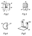
- the floating mass 2 (see in particular figures 2,3 and 4) has a central bridge portion 16 from which depend 2 skirt portions 17,18 partially to surround the hollow tube 1.
- a lower surface 19 of the bridge portion 16 is adapted to contact the chamfered free end 7 of the tube 1.
- the floating mass 2 is a loose sliding fit within the bore 3 on an axis of sliding movement 20 extends through the bore 3.
- An axis 21 of the tube makes an angle alpha between the axes 20, 21 which is less than 90°.
- a wall thickness of the tube 1 at the groove 5 of the order of 0.1 mm allowed fracture to occur in bending from a threshold acceleration value of approximately 1800g.
- the floating mass 2 weighed 2g and was composed of a proprietary heavy metal having a density in the region of 17 gcm -3 .
- the angle alpha is 65°, the tube 1 being arranged so that the upper portion 6 thereof ends up at 90° to the axis 20, following fracture.
- the skirt portions 17, 18 act as guides to ensure that the tube 1 is bent in the plane of the paper by the mass 2.
- the embodiment described above may be modified to incorporate an anti-rattle device.
- such a device could comprise a compression spring 24 located within a recess in the mass 2.
- the spring-loaded device 25 of Figure 5 is located within the bore 3 and positioned so that the lower face of the mass 2 rests on two arms 26a, 26b, of the device 25.
- the arms 26a, 26b are strong enough to hold the mass off the tube 1 until the threshold acceleration is reached, whereupon, the arms 26a, 26b deflect, allowing the mass to move towards the tube 1.
- This alternative device 25 is particularly advantageous for use in cases where the tube 1 is made from a relatively fragile material such as glass or plastics.
- the floating mass 2 is dispensed with and the tube upper portion is enlarged to create its own inertial mass.
- the valve of the present invention provides good predictability as to fracture of the lever arm for use in applications where reliability is paramount.
Landscapes
- Engineering & Computer Science (AREA)
- General Engineering & Computer Science (AREA)
- Mechanical Engineering (AREA)
- Physics & Mathematics (AREA)
- Thermal Sciences (AREA)
- Details Of Valves (AREA)
Description
Claims (11)
- A shock valve for releasing a fluid in response to an acceleration applied thereto above a threshold value, the valve including a fixed lever arm (1) defining a sealed fluid passageway (4) therein and a mass (2), the lever arm (1) and mass (2) being relatively positioned so that during the said acceleration the mass (2) exerts a bending moment on the arm (1) to fracture same and break the fluid seal, the mass (2) being shaped at least partially to surround the lever arm (1) whereby to guide the arm during bending thereof.
- A shock valve as in claim 1 in which the mass (2) forms an integral part with the lever arm (1).
- A shock valve as in claim 1 in which the mass (2) floats substantially along an axis of a bore (3) within which the mass (2) is slideable and into which the lever arm (1) projects.
- A shock valve as in claim 3 in which the lever arm (1) and the mass (2) are positioned and formed whereby the centre of mass of the mass (2) is aligned with a point of contact between said mass (2) and arm (1).
- A shock valve as in claim 1 in which the lever arm (1) has a weakening (5) formed therein to encourage fracture thereat.
- A shock valve as in claim 5 in which the weakening comprises a peripheral groove (5) formed around the arm (1).
- A shock valve as in claim 6 in which the peripheral groove (5) is of substantially rectangular cross-section.
- A shock valve as in claim 5,6, or 7, in which the weakening (5) is formed in a surrounding wall of the sealed passageway (4).
- A shock valve as in any of claims 1-8 including an anti-rattle device (24, 25) for preventing the mass (2) vibrating within the bore (3).
- A shock valve as in claim 9 in which the anti-rattle device is a compression spring (24) located within a recess in the mass (2).
- A shock valve as in claim 9 in which the anti-rattle device is a spring-loaded element (25) located within said bore (3) and incorporating support means (26a,26b) for lifting the mass (2) clear of the lever arm (1).
Applications Claiming Priority (1)
| Application Number | Priority Date | Filing Date | Title |
|---|---|---|---|
| PCT/GB1997/002491 WO1999014521A1 (en) | 1997-09-15 | 1997-09-15 | A shock valve |
Publications (2)
| Publication Number | Publication Date |
|---|---|
| EP1015799A1 EP1015799A1 (en) | 2000-07-05 |
| EP1015799B1 true EP1015799B1 (en) | 2003-03-19 |
Family
ID=10807233
Family Applications (1)
| Application Number | Title | Priority Date | Filing Date |
|---|---|---|---|
| EP97940251A Expired - Lifetime EP1015799B1 (en) | 1997-09-15 | 1997-09-15 | A shock valve |
Country Status (4)
| Country | Link |
|---|---|
| EP (1) | EP1015799B1 (en) |
| DE (1) | DE69720075T2 (en) |
| IL (1) | IL135021A (en) |
| WO (1) | WO1999014521A1 (en) |
Family Cites Families (3)
| Publication number | Priority date | Publication date | Assignee | Title |
|---|---|---|---|---|
| GB728857A (en) * | 1952-01-24 | 1955-04-27 | Radikal Werk G M B H | Improvements in or relating to compressed gas containers for fire extinguishers |
| US3084705A (en) * | 1961-03-13 | 1963-04-09 | Canrad Prec Ind | Device for rupturing glass seals |
| FR2733306B1 (en) * | 1995-04-21 | 1997-05-23 | Cryotechnologies | VERY FAST MINIATURE COOLING DEVICE |
-
1997
- 1997-09-15 EP EP97940251A patent/EP1015799B1/en not_active Expired - Lifetime
- 1997-09-15 WO PCT/GB1997/002491 patent/WO1999014521A1/en not_active Ceased
- 1997-09-15 DE DE69720075T patent/DE69720075T2/en not_active Expired - Fee Related
- 1997-09-15 IL IL13502197A patent/IL135021A/en not_active IP Right Cessation
Also Published As
| Publication number | Publication date |
|---|---|
| IL135021A (en) | 2004-02-08 |
| DE69720075D1 (en) | 2003-04-24 |
| DE69720075T2 (en) | 2003-11-20 |
| WO1999014521A1 (en) | 1999-03-25 |
| EP1015799A1 (en) | 2000-07-05 |
| IL135021A0 (en) | 2001-05-20 |
Similar Documents
| Publication | Publication Date | Title |
|---|---|---|
| CN101711320B (en) | Single-action discharge valve | |
| MX2011004806A (en) | Impulse actuated valve. | |
| EP1800972A1 (en) | Inflator having an improved closure cap | |
| EP0512747A1 (en) | A method and apparatus for supplying gas | |
| US5535730A (en) | Apparatus and methods for removing hazardous contents from compressed gas cylinders | |
| NO343753B1 (en) | Hydraulic crushing mechanism | |
| US5551517A (en) | Automatic fire extinguishing discharge valve | |
| EP1015799A1 (en) | A shock valve | |
| GB2323170A (en) | A shock valve | |
| EP3260175B1 (en) | Mount de-actuated safety mechanism | |
| US5373790A (en) | System for self destruction of a carrier shell submunition by chemical attack | |
| US4627354A (en) | Launchable aerosol grenade | |
| US4034777A (en) | Apparatus to pierce a fluid-transport pipe and control the fluid-flow therefrom | |
| EP0862003B1 (en) | Release mechanism for a pressure vessel | |
| US6386111B1 (en) | Stemming arrangement and method for blast holes | |
| US5119878A (en) | Impact activated vehicle-based fire extinguisher | |
| US6389976B1 (en) | Hard target fuze | |
| US4970936A (en) | Gas reservoir actuation device | |
| US4060188A (en) | Impact nailing arrangement | |
| US11117005B2 (en) | Device for dispensing a pressurized material | |
| US7219530B2 (en) | High g-force shock pulse generator systems and methods | |
| US5125343A (en) | Fluid decelerator for high energy projectiles | |
| US4340077A (en) | Method of and apparatus for remotely controlling orifice-opening and orifice-closing operations | |
| EP3072557A1 (en) | Fire suppressant apparatus | |
| GB2123531A (en) | Valves |
Legal Events
| Date | Code | Title | Description |
|---|---|---|---|
| PUAI | Public reference made under article 153(3) epc to a published international application that has entered the european phase |
Free format text: ORIGINAL CODE: 0009012 |
|
| 17P | Request for examination filed |
Effective date: 20000126 |
|
| AK | Designated contracting states |
Kind code of ref document: A1 Designated state(s): CH DE ES FR IT LI NL SE |
|
| 17Q | First examination report despatched |
Effective date: 20010515 |
|
| GRAH | Despatch of communication of intention to grant a patent |
Free format text: ORIGINAL CODE: EPIDOS IGRA |
|
| RAP1 | Party data changed (applicant data changed or rights of an application transferred) |
Owner name: MBDA UK LIMITED |
|
| GRAH | Despatch of communication of intention to grant a patent |
Free format text: ORIGINAL CODE: EPIDOS IGRA |
|
| GRAA | (expected) grant |
Free format text: ORIGINAL CODE: 0009210 |
|
| AK | Designated contracting states |
Designated state(s): CH DE ES FR IT LI NL SE |
|
| PG25 | Lapsed in a contracting state [announced via postgrant information from national office to epo] |
Ref country code: NL Free format text: LAPSE BECAUSE OF FAILURE TO SUBMIT A TRANSLATION OF THE DESCRIPTION OR TO PAY THE FEE WITHIN THE PRESCRIBED TIME-LIMIT Effective date: 20030319 Ref country code: LI Free format text: LAPSE BECAUSE OF FAILURE TO SUBMIT A TRANSLATION OF THE DESCRIPTION OR TO PAY THE FEE WITHIN THE PRESCRIBED TIME-LIMIT Effective date: 20030319 Ref country code: CH Free format text: LAPSE BECAUSE OF FAILURE TO SUBMIT A TRANSLATION OF THE DESCRIPTION OR TO PAY THE FEE WITHIN THE PRESCRIBED TIME-LIMIT Effective date: 20030319 |
|
| REG | Reference to a national code |
Ref country code: CH Ref legal event code: EP |
|
| REF | Corresponds to: |
Ref document number: 69720075 Country of ref document: DE Date of ref document: 20030424 Kind code of ref document: P |
|
| PG25 | Lapsed in a contracting state [announced via postgrant information from national office to epo] |
Ref country code: SE Free format text: LAPSE BECAUSE OF FAILURE TO SUBMIT A TRANSLATION OF THE DESCRIPTION OR TO PAY THE FEE WITHIN THE PRESCRIBED TIME-LIMIT Effective date: 20030619 |
|
| PGFP | Annual fee paid to national office [announced via postgrant information from national office to epo] |
Ref country code: FR Payment date: 20030811 Year of fee payment: 7 |
|
| PGFP | Annual fee paid to national office [announced via postgrant information from national office to epo] |
Ref country code: DE Payment date: 20030821 Year of fee payment: 7 |
|
| NLV1 | Nl: lapsed or annulled due to failure to fulfill the requirements of art. 29p and 29m of the patents act | ||
| PG25 | Lapsed in a contracting state [announced via postgrant information from national office to epo] |
Ref country code: ES Free format text: LAPSE BECAUSE OF FAILURE TO SUBMIT A TRANSLATION OF THE DESCRIPTION OR TO PAY THE FEE WITHIN THE PRESCRIBED TIME-LIMIT Effective date: 20030930 |
|
| REG | Reference to a national code |
Ref country code: CH Ref legal event code: PL |
|
| ET | Fr: translation filed | ||
| PLBE | No opposition filed within time limit |
Free format text: ORIGINAL CODE: 0009261 |
|
| STAA | Information on the status of an ep patent application or granted ep patent |
Free format text: STATUS: NO OPPOSITION FILED WITHIN TIME LIMIT |
|
| 26N | No opposition filed |
Effective date: 20031222 |
|
| PG25 | Lapsed in a contracting state [announced via postgrant information from national office to epo] |
Ref country code: DE Free format text: LAPSE BECAUSE OF NON-PAYMENT OF DUE FEES Effective date: 20050401 |
|
| PG25 | Lapsed in a contracting state [announced via postgrant information from national office to epo] |
Ref country code: FR Free format text: LAPSE BECAUSE OF NON-PAYMENT OF DUE FEES Effective date: 20050531 |
|
| REG | Reference to a national code |
Ref country code: FR Ref legal event code: ST |
|
| PG25 | Lapsed in a contracting state [announced via postgrant information from national office to epo] |
Ref country code: IT Free format text: LAPSE BECAUSE OF NON-PAYMENT OF DUE FEES Effective date: 20050915 |