EP1015379B1 - Dual-stream filling valve - Google Patents
Dual-stream filling valve Download PDFInfo
- Publication number
- EP1015379B1 EP1015379B1 EP19980931557 EP98931557A EP1015379B1 EP 1015379 B1 EP1015379 B1 EP 1015379B1 EP 19980931557 EP19980931557 EP 19980931557 EP 98931557 A EP98931557 A EP 98931557A EP 1015379 B1 EP1015379 B1 EP 1015379B1
- Authority
- EP
- European Patent Office
- Prior art keywords
- primary
- tube
- valve
- fill tube
- fill
- Prior art date
- Legal status (The legal status is an assumption and is not a legal conclusion. Google has not performed a legal analysis and makes no representation as to the accuracy of the status listed.)
- Expired - Lifetime
Links
Images



Classifications
-
- B—PERFORMING OPERATIONS; TRANSPORTING
- B65—CONVEYING; PACKING; STORING; HANDLING THIN OR FILAMENTARY MATERIAL
- B65B—MACHINES, APPARATUS OR DEVICES FOR, OR METHODS OF, PACKAGING ARTICLES OR MATERIALS; UNPACKING
- B65B39/00—Nozzles, funnels or guides for introducing articles or materials into containers or wrappers
- B65B39/001—Nozzles, funnels or guides for introducing articles or materials into containers or wrappers with flow cut-off means, e.g. valves
- B65B39/004—Nozzles, funnels or guides for introducing articles or materials into containers or wrappers with flow cut-off means, e.g. valves moving linearly
-
- B—PERFORMING OPERATIONS; TRANSPORTING
- B65—CONVEYING; PACKING; STORING; HANDLING THIN OR FILAMENTARY MATERIAL
- B65B—MACHINES, APPARATUS OR DEVICES FOR, OR METHODS OF, PACKAGING ARTICLES OR MATERIALS; UNPACKING
- B65B3/00—Packaging plastic material, semiliquids, liquids or mixed solids and liquids, in individual containers or receptacles, e.g. bags, sacks, boxes, cartons, cans, or jars
- B65B3/26—Methods or devices for controlling the quantity of the material fed or filled
- B65B3/30—Methods or devices for controlling the quantity of the material fed or filled by volumetric measurement
- B65B3/32—Methods or devices for controlling the quantity of the material fed or filled by volumetric measurement by pistons co-operating with measuring chambers
- B65B3/326—Methods or devices for controlling the quantity of the material fed or filled by volumetric measurement by pistons co-operating with measuring chambers for dosing several products to be mixed
-
- B—PERFORMING OPERATIONS; TRANSPORTING
- B65—CONVEYING; PACKING; STORING; HANDLING THIN OR FILAMENTARY MATERIAL
- B65B—MACHINES, APPARATUS OR DEVICES FOR, OR METHODS OF, PACKAGING ARTICLES OR MATERIALS; UNPACKING
- B65B37/00—Supplying or feeding fluent-solid, plastic, or liquid material, or loose masses of small articles, to be packaged
- B65B37/06—Supplying or feeding fluent-solid, plastic, or liquid material, or loose masses of small articles, to be packaged by pistons or pumps
-
- B—PERFORMING OPERATIONS; TRANSPORTING
- B65—CONVEYING; PACKING; STORING; HANDLING THIN OR FILAMENTARY MATERIAL
- B65B—MACHINES, APPARATUS OR DEVICES FOR, OR METHODS OF, PACKAGING ARTICLES OR MATERIALS; UNPACKING
- B65B39/00—Nozzles, funnels or guides for introducing articles or materials into containers or wrappers
-
- B—PERFORMING OPERATIONS; TRANSPORTING
- B67—OPENING, CLOSING OR CLEANING BOTTLES, JARS OR SIMILAR CONTAINERS; LIQUID HANDLING
- B67C—CLEANING, FILLING WITH LIQUIDS OR SEMILIQUIDS, OR EMPTYING, OF BOTTLES, JARS, CANS, CASKS, BARRELS, OR SIMILAR CONTAINERS, NOT OTHERWISE PROVIDED FOR; FUNNELS
- B67C3/00—Bottling liquids or semiliquids; Filling jars or cans with liquids or semiliquids using bottling or like apparatus; Filling casks or barrels with liquids or semiliquids
- B67C3/02—Bottling liquids or semiliquids; Filling jars or cans with liquids or semiliquids using bottling or like apparatus
- B67C3/04—Bottling liquids or semiliquids; Filling jars or cans with liquids or semiliquids using bottling or like apparatus without applying pressure
-
- B—PERFORMING OPERATIONS; TRANSPORTING
- B67—OPENING, CLOSING OR CLEANING BOTTLES, JARS OR SIMILAR CONTAINERS; LIQUID HANDLING
- B67C—CLEANING, FILLING WITH LIQUIDS OR SEMILIQUIDS, OR EMPTYING, OF BOTTLES, JARS, CANS, CASKS, BARRELS, OR SIMILAR CONTAINERS, NOT OTHERWISE PROVIDED FOR; FUNNELS
- B67C3/00—Bottling liquids or semiliquids; Filling jars or cans with liquids or semiliquids using bottling or like apparatus; Filling casks or barrels with liquids or semiliquids
- B67C3/02—Bottling liquids or semiliquids; Filling jars or cans with liquids or semiliquids using bottling or like apparatus
- B67C3/20—Bottling liquids or semiliquids; Filling jars or cans with liquids or semiliquids using bottling or like apparatus with provision for metering the liquids to be introduced, e.g. when adding syrups
- B67C3/208—Bottling liquids or semiliquids; Filling jars or cans with liquids or semiliquids using bottling or like apparatus with provision for metering the liquids to be introduced, e.g. when adding syrups specially adapted for adding small amounts of additional liquids, e.g. syrup
-
- B—PERFORMING OPERATIONS; TRANSPORTING
- B65—CONVEYING; PACKING; STORING; HANDLING THIN OR FILAMENTARY MATERIAL
- B65B—MACHINES, APPARATUS OR DEVICES FOR, OR METHODS OF, PACKAGING ARTICLES OR MATERIALS; UNPACKING
- B65B39/00—Nozzles, funnels or guides for introducing articles or materials into containers or wrappers
- B65B2039/009—Multiple outlets
-
- Y—GENERAL TAGGING OF NEW TECHNOLOGICAL DEVELOPMENTS; GENERAL TAGGING OF CROSS-SECTIONAL TECHNOLOGIES SPANNING OVER SEVERAL SECTIONS OF THE IPC; TECHNICAL SUBJECTS COVERED BY FORMER USPC CROSS-REFERENCE ART COLLECTIONS [XRACs] AND DIGESTS
- Y10—TECHNICAL SUBJECTS COVERED BY FORMER USPC
- Y10T—TECHNICAL SUBJECTS COVERED BY FORMER US CLASSIFICATION
- Y10T137/00—Fluid handling
- Y10T137/8593—Systems
- Y10T137/87571—Multiple inlet with single outlet
- Y10T137/87676—With flow control
- Y10T137/87684—Valve in each inlet
Definitions
- This invention pertains to a dual stream filling valve. More particularly, this invention pertains to a dual stream filling valve for introducing a plurality of flowable products into a container in a filling apparatus.
- Various types of filling apparatuses are known in the art.
- two or more streams of, for example, liquid are introduced into a single package, such as milk and cream mixed together into a single container.
- Such mixing must be done in a controlled, metered manner to assure that the proper quantities and proportions of each are added to the container,
- milk is available having varying milk fat content, such as skim milk, "1%” and “2%” milk, as well as whole milk.
- the milk fat content is generally controlled by the proportion of cream to milk in the final product.
- cream is added to skim milk to produce the various percentages of milk fat content.
- the dual-stream filling valve can be used.
- the milk is referred to as the primary fluid and the cream is referred to as the secondary fluid.
- flowable product other than milk such as dried, particulate or powdered products, as well as a combination of such solid (e.g., particulate and powdered) and liquid materials.
- the combination of primary and secondary fluids in a single container is carried out using a dual-stream valve, e.g. WO 96/09957 .
- the dual-stream valve has concentric outer and inner filling tubes (primary and secondary, respectively) that are in communication with respective liquid storage tanks or reservoirs.
- a valve element such as a plug
- the plug is moved or actuated by a rod that penetrates the secondary tube, and longitudinally traverses through the inside of the tube from the tube top to the bottom where it is joined with the valve plug.
- the rod that traverses through the filling tube requires space or volume that could otherwise be devoted to secondary fluid flow.
- this arrangement positions moving, mechanical components directly in the secondary fluid, which is typically food product.
- penetration of the rod through each filling tube requires the use of one or more seals to assure that the food product is fully isolated from the environs.
- a dual-stream filling valve that does not impact or reduce the usable space or volume of the secondary filling tube or conversely require an increase in the diameter of the tube.
- Such a dual-stream valve has a minimum of moving mechanical parts that directly contact the flowable material in the system, typically a food product.
- such a dual-stream valve minimizes the number and complexity of the seals required which, in turn, reduces the opportunity for leakage into and out of the valve.
- the present invention is directed at a dual stream fill system for a packaging machine, having a primary and a secondary filling tube.
- the primary filling tube is for introducing a first flowable food into a container through a discharge end (42); the secondary filling tube extends concentrically within the primary tube for introducing a second flowable food into the container through an outlet.
- a valve mechanism controls the flow of second flowable product from the secondary filling tube.
- the secondary tube includes a section which penetrates the primary tube through a first opening intermediate the inlet and discharge ends of the primary tube, and the valve mechanism is controlled by an activating mechanism at least partially within the primary tube but wholly external of the secondary tube.
- the valve mechanism can be movable relative to both the primary filling tube and the secondary filling tube.
- the mechanism typically includes a valve plug operable relative to the secondary filling tube, and which can be positioned in the primary filling tube internal flow region.
- the plug may include a portion that is movable relative to the secondary filling tube between an opened state wherein flow communication is established between the internal flow regions of the primary and secondary filling tubes and a closed state wherein flow communication is terminated between the internal flow regions of the primary and secondary filling tubes.
- the primary and the secondary filling tubes are stationary relative to one another.
- the valve mechanism includes an actuating lever extending at least in part through a second opening in the primary filling tube, normally intermediate the first opening and the inlet end.
- a connecting member extends between the actuating lever and the valve element, which is preferably a valve ball, to support the ball.
- the connecting member can be configured as a caged rod assembly to support the valve ball so that the ball freely rotates within the cage.
- the valve ball is self-aligning and self-cleaning.
- a valve plug element is fixedly mounted to the primary filling tube proximal to the discharge end.
- the primary filling tube includes a stationary upper body portion, a stationary lower body portion and a reciprocating intermediate housing portion between the stationary upper and lower body portions.
- the intermediate housing is connected to the upper and lower stationary body portions by cooperating, preferably sliding joints.
- the secondary filling tube penetrates the primary filling tube at the intermediate housing and reciprocates with the intermediate housing relative to the valve plug by movement of the cooperating joints.
- this embodiment of the dual-stream valve includes diaphragms that extend about the cooperating joints to isolate the sliding joints from the flowable material in the valve.
- a preferred configuration of the sliding joints includes annular inner and outer sliding members.
- the valve element can be formed as a valve cone.
- a well suited cone includes at least one, and preferably four V-grooves that extend along the length of the cone from the top of the cone downward.
- the V-grooves have a cross-sectional area that decreases along the length of the cone.
- the secondary filling tube is stationary relative to the primary filling tube and is positioned relative to the primary filling tube so as to define a sealed passage therebetween.
- the valve plug includes a pressure responsive seat element that moves, relative to the secondary filling tube, between closed position and open positions.
- the seat element is operably connected to a biasing element to bias the seat element in either the opened or closed positions.
- Pressure can be provided to the seat element by a gas, such as air or nitrogen-Alternately, the pressure responsive seat element can be configured to operate by vacuum. In still another configuration, the pressure responsive seat element can be actuated by a liquid, e.g., hydraulic system.
- FIGS. 2-4 there is shown one embodiment of a dual-stream filling valve 10 embodying the principles of the present invention.
- the valve 10 is illustrated installed within a filling apparatus 12.
- the apparatus 12 may be used for packaging flowable materials, such as both skim milk and cream in a single container to produce milk having a specific, e.g., 2%, milk fat content.
- the flow path for the skim milk will be referred to as the primary material or fill path, indicated at 14, and the flow path for the cream will be referred to as the secondary material or fill path, indicated at 16.
- the components within the primary and secondary fill paths 14, 16 will likewise be referred to as primary and secondary components.
- FIG. 1 illustrates, schematically, the apparatus 12.
- FIG. 2 is one physical arrangement of such an apparatus 12.
- the apparatus 12 includes, generally, a primary product or material reservoir or storage tank 18, a secondary reservoir 20, primary and secondary material pumps, 22, 24, respectively, for the primary and secondary materials, and primary and secondary material transfer connections 26, 28 to transfer the respective flowable materials from the pumps 22, 24 to the dual-stream valve 10.
- the primary flow path 14 may include a resuction valve 30 that absorbs any pressure increase or spike as the flow of material into a container is terminated. This prevents the material from dripping or dropping during the periods following flow termination and between periods of material flow.
- the apparatus 12 components include flanges 32 that are clamped or connected to one another by dairy clamps 34.
- the flanges 32 may include seal elements, such as O-rings 36, to facilitate maintaining a seal between the components in the fill or flow paths 14, 16 and the environs.
- the valve 10 includes primary and secondary, i.e., outer and inner concentrically disposed product transfer or filling tubes 38, 40, respectively.
- the outer or primary transfer tube 38 may carry, for example, skim milk, from the primary storage tank 18, while the inner or secondary tube 40 may carry, for example, cream from the secondary tank 20.
- the flowable materials can be mixed immediately prior to and as they are introduced into a common container. That is, the primary and secondary materials are mixed at about the discharge end 42 of the primary tube filling tube 38. Alternately, one of the materials can be first introduced into the container with the other material introduced subsequent thereto.
- the primary and secondary storage tanks, 18, 20 can contain skim milk and whole milk, respectively, to produce the desired end product.
- the material in the tanks, 18, 20 can be interchanged to produce other desired products.
- other, non-liquid and partially-liquid flowable materials as well as combinations thereof can be packaged using the present filling apparatus 12.
- Reference herein to flowable material, material, flowable product, product, and the like, shall be construed to include all such liquid, non-liquid and partially-liquid flowable materials, including both food products and non-food products.
- the primary filling tube 38 includes a filling nozzle 44 at the discharge end 42 thereof.
- the nozzle 44 conforms to the size and shape of the container that is being filled, as the flowable material exits the nozzle 44.
- nozzles 44 are formed of a pliable material, such as a food grade, e.g., FDA approved, silicone rubber, and are configured to open outward to conform to the container opening upon initiation of product flow and to fold inward upon termination of product flow. The inward folding of the nozzle 44 minimizes any dripping or dropping of material from the tube 38 between filling of containers.
- the primary filling tube 38 has a main body portion 46 defining the flow path 14 through which the primary material flows from the pump 22 to the nozzle 44.
- the body 46 includes a secondary tube opening or penetration 48 therein that is positioned intermediate the primary tube 38 inlet and discharge ends, 50, 42, respectively, and is configured to receive the secondary tube 40.
- the penetration 48 is sealed about the secondary tube 40 to isolate the flow path 14 from the environs.
- the secondary tube 40 has valve means 54 associated therewith.
- the valve means 54 and the secondary tube 40 move, at least in part, relative to one another to establish or initiate and terminate flow of the secondary material from the secondary tube 40.
- the valve 54 can include, for example, a valve cone, such as a valve ball or plug.
- the valve means 54 lies in the material flow path 16. When the valve 54 is in the opened position or state, flow communication is established between the primary and secondary filling tubes 38 and 40, thus permitting material to flow from the secondary tube 40 to the primary tube 38. Conversely, when the valve 54 is in the closed position or state, flow communication, and thus material or product flow, between the primary and secondary tubes 38 and 40 is terminated.
- the primary and secondary filling tubes 38, 40 are essentially rigid structures.
- the secondary tube 40 is fixedly mounted to the primary tube body 46.
- the valve means 54 includes an actuator 56 having a valve lever 58 that penetrates the primary tube body 46 at a penetration 59 that is intermediate the secondary penetration 48 and the inlet end 50 of the primary tube 38.
- the valve lever 58 extends into the primary tube flow region 60 and pivots generally longitudinally along the flow path 14.
- the lever 58 is positioned and pivots within a sleeve-like element 62 that extends from a diaphragm seal 64, into the primary flow path 14.
- the seal 64 and sleeve 62 isolate the portion of the lever 58 internal to the primary tube 38, and thus the primary material from the environs.
- the lever 58 is operably connected to the valve means 54 to establish and terminate flow from the secondary filling tube 40.
- the valve means 54 is a valve ball 66 that is operably connected to the lever 58 by a actuating rod assembly 68.
- the valve ball 66 is formed of a polymeric material, such as the aforementioned silicone. Silicone has been found to be an ideal material for this application because of its ability to conform to the tube 40 opening thus creating a liquid-tight or material-tight seal, and because of its hygienic, e.g., clean-ability, characteristics.
- the rod assembly 68 can include a rectangular hoop 70 that extends along two sides, or 180° about the secondary filling tube 40, as seen in FIGS. 3-4 , and can include J-shaped members 72 that extend from the base 74 of the hoop 70, essentially forming a rod cage 76.
- the cage 76 is configured to essentially "ride" along the outside of the secondary tube 40. A distance or gap of about 1/4 mm between the rods 70,72 and the tube 40 is anticipated to be sufficient to prevent binding of the rods, 70, 72, and tube 40, while permitting free, guided movement of the rods 70, 72. In this manner, the valve ball 66 is surrounded at 90° intervals by the rod cage 76, and the ball 66 can freely rotate within the cage 76.
- permitting the ball 66 to freely rotate enhances the ability of the ball 66 to seal the secondary tube 40. Because the ball 66 rotates, the area of the ball 66 that is subject to compression against the secondary tube discharge end 78 will likely change from one compression to the next. Thus, free rotation of the ball 66 distributes compression on the ball 66 over more of the surface of the ball 66 and subjects it to less localized wear as a result of the continuous compression of the softer, resilient ball 66 against the secondary tube 40.
- free rotation of the ball 66 will increase the ability of the ball 66 to "self-clean.” That is, there will be less accumulation or build-up of product on the ball 66, thus reducing the opportunity for improper seating of the ball 66 at the tube discharge end 78.
- the rod assembly 68 includes a connecting member 80 that is adapted to receive the lever 58.
- the connecting member 80 and lever 58 are configured such that, as the lever 58 is pivoted, the rod cage 76 is moved toward and away from the secondary tube discharge end 78. As the cage 76 is moved toward and away from the discharge end 78, the ball 66 seats and unseats from the tube 40.
- valve ball 66 is also self aligning. That is, even if the ball 66 is slightly off of center as it is brought into contact with tube 40, the spherical shape of the ball 66 will cause it to shift or move into alignment with the discharge end 78 and form a seal thereacross.
- Other valve cone shapes and valve types such as those disclosed herein, as well as standard plugs or plug-cocks, truncated plug-cocks, flap-type valves and the like can also be used with the rod assembly 68 arrangement. Such other shapes and configurations of valve plugs are within the scope of the present invention.
- the lever 58 is actuated by an external drive 82 that is isolated from the flowable material.
- an external drive 82 that is isolated from the flowable material.
- the manner of actuating the lever 58 can include mechanical drives, electro-mechanical drives, hydraulic and pneumatic drives. Such drives, and their use and application, will be readily recognized by those skilled in the art.
- the primary and secondary filling tubes 38, 40 are essentially rigid, fixed flowable material carrying conduits.
- the valve ball 66 and secondary tube 40 move relative to one another. This arrangement provides a valve ball 66 that is readily accessible for maintenance and inspection by removing the mechanical components of the actuating assembly 68.
- the primary tube 112 includes first and second, e.g., upper and lower stationary body portions 114, 116 and an intermediate housing portion 118 positioned between the upper and lower body portions 114 and 116.
- the intermediate housing 118 which includes an opening or penetration 120 for the secondary tube 122, reciprocates between, and relative to, the upper and lower body portions 114 and 116.
- Valve means 124 such as the illustrated valve cone 126, is fixedly mounted to one of the stationary body portions 114, 116, preferably, the lower body portion 116.
- the secondary tube 122 likewise reciprocates, and is moved into and out of contact with the valve cone 126.
- the intermediate housing 118 is moved downward ( FIG. 6b ), toward the discharge end 128 of the primary tube 112, the secondary tube 122 moves into contact with the valve cone 126, and the flow of material therefrom is terminated.
- the intermediate housing 118 is moved upwardly ( FIG. 6a ), toward the inlet end 130 of the primary tube 112, the secondary tube 122 is moved out of contact with the valve cone 126. In this position, the valve 124 is open, thus establishing flow communication between the primary and secondary tubes 112, 122.
- the upper body portion 114 and intermediate housing 118 and the intermediate housing 118 and lower body portion 116 are connected to one another by cooperating, moving connectors or joints 132, 134.
- the joints 132, 134 permit the intermediate housing 118 to reciprocate relative to and between the fixed upper and lower body portions 114, 116.
- the secondary tube 122 With the secondary filling tube 122 fixedly mounted to the intermediate housing 118, the secondary tube 122 likewise reciprocates relative to the upper and lower body portions 114, 116.
- each sliding connector 132, 134 includes an inner slide member 132a, 134a and an outer slide member 132b, 134b that are concentric relative to one another.
- the inner slide members 132a, 134a are configured to slide, in a telescopic manner within their respective outer members 132b, 134b.
- the outer members 132b, 134b each include a stop or end wall 136 to prevent the inner members 132a, 134a from over-inserting into the outer members 132b, 134b.
- the sliding members 132, 134 are isolated from the flowable material by seal elements 138, such as the illustrated flexible diaphragms.
- the diaphragms 138 flex as the joints 132, 134 slide between the retracted state, as illustrated at 140, and the extended state, as illustrated at 142.
- the diaphragms 138 are retained in place by rings or lips 144 integral with the diaphragms 138 that are positioned in grooves 146 formed in the flanges 148. As the flanges 148 are compressed together, the diaphragms 138 are secured in place.
- the components are clamped together at the flanges 148 by dairy clamps (see clamp 34 in FIG. 3 ).
- the clamps 34 maintain the components of the apparatus 12 rigid and the material flow path isolated from the environs.
- the diaphragm 138 like the valve nozzle 150 is formed of a food-grade material, such as silicone rubber.
- the diaphragm 138 material is formulated with sufficient elasticity so that the diaphragm 138 will withstand repeated and continuous flexing as the intermediate housing 118 and secondary filling tube 122 are reciprocated.
- the hygienic standards that may be required or desired for the process can be readily achieved and maintained, while isolating the moving connectors 132, 134 from the flowable product.
- FIGS. 6a and 6b illustrate the valve 110 with the valve in the opened and closed positions, respectively.
- the joints 132, 134 are similarly oriented and cooperate with one another to permit the intermediate housing 118 to reciprocate within a fixed linear space.
- the intermediate housing 118 reciprocates between about 10 millimeters (mm) and 13mm, from the top of stroke or opened position as shown in FIG. 6a , to the bottom of stroke or closed position as shown in FIG. 6b .
- valve cone 126 is illustrated in place in the valve 110 in FIGS. 6a and 6b .
- the cone 126 is a resilient member that is formed of, for example, a silicone rubber, similar to the other non-metallic, wetted, silicone components.
- the valve cone 126 is supported in place in the primary flow chamber 152 by a plurality of rigid support elements 154 that extend inwardly from the inside surface of the primary filling tube 112.
- the elements 154 are positioned about the primary tube flow chamber 152 so as to minimize interfering with the flowing material.
- the cone 126 includes guide means 156 to maintain the cone 126 in alignment with the secondary tube 122.
- the guide means can include the ribs 156 as shown on the cone 126 of FIGS. 6a and 6b , to facilitate proper seating of the reciprocating secondary tube 122 with the cone 126.
- V-groove valve cone 170 includes a cylindrical, barrel-like main body portion 172.
- the cone 170 has a plurality of V-shaped, angled grooves as indicated at 174 formed in the body 172.
- the angling of each groove 174 is such that the cross-sectional area of the groove 174 is greatest at the top 176 of the cone 170 and decreases downward, along the length l of the cone 170 and the groove 174.
- the grooves 174 have a V-shape as viewed from the front and sides 178,180 of the cone as seen in FIG. 7 , and as seen from the top 176 of the cone 170.
- the grooves 174 as viewed from the top 176 of the cone 170, can have a curvilinear cross-section, such as quarter-circular, semicircular and parabolic shaped cross-sections. All such cross-sectional shapes are within the scope of the present invention.
- V-groove 174 configuration provides enhanced flow control characteristics.
- the cone 170 resides within the discharge end 158 of the secondary tube 122, when in the closed position, thus maintaining alignment of the cone 170 and tube 122.
- the cone 170 includes guide or alignment means to maintain the cone 170 in alignment with the secondary tube 122 as they are engaged with one another.
- Such guide means can be internal to the tube 122 or external to the cone 170.
- alignment of the cone 126 and tube 122 is effected by the ribs 156 that extend outwardly from the cone 170.
- alignment can be maintained by a beveled edge or chamber 182 along the top 126 and sides 180 of the cone 170.
- the intermediate housing 122 can be reciprocated by any of a variety of drive means 160, including mechanical drives, electro-mechanical drives, hydraulic and pneumatic drives. Such drives, and their use and application, will be readily recognized by those skilled in the art. The use of all such drives are within the scope of the present invention as defined by the appended claims.
Landscapes
- Engineering & Computer Science (AREA)
- Mechanical Engineering (AREA)
- Supply Of Fluid Materials To The Packaging Location (AREA)
- Filling Of Jars Or Cans And Processes For Cleaning And Sealing Jars (AREA)
- Multiple-Way Valves (AREA)
- Basic Packing Technique (AREA)
Abstract
Description
- This invention pertains to a dual stream filling valve. More particularly, this invention pertains to a dual stream filling valve for introducing a plurality of flowable products into a container in a filling apparatus.
- Various types of filling apparatuses are known in the art. In one type of apparatus, two or more streams of, for example, liquid are introduced into a single package, such as milk and cream mixed together into a single container. Such mixing must be done in a controlled, metered manner to assure that the proper quantities and proportions of each are added to the container,
- Consumers will readily recognize that milk is available having varying milk fat content, such as skim milk, "1%" and "2%" milk, as well as whole milk. The milk fat content is generally controlled by the proportion of cream to milk in the final product. Often, cream is added to skim milk to produce the various percentages of milk fat content. This is one exemplary process in which the dual-stream filling valve can be used. In such a process, the milk is referred to as the primary fluid and the cream is referred to as the secondary fluid. It will be recognized that such an arrangement can be used for flowable product other than milk, such as dried, particulate or powdered products, as well as a combination of such solid (e.g., particulate and powdered) and liquid materials.
- In one known arrangement, the combination of primary and secondary fluids in a single container is carried out using a dual-stream valve, e.g.
WO 96/09957 - While such known dual-stream valves function well, they can require considerable maintenance and inspection. As will be apparent, each such seal provides the opportunity for leakage. Moreover, as noted above, such systems require space within the secondary tube, which, consequently increases the diameter of the secondary tube. Additionally, known dual-stream filling arrangements can create localized spots or locations that tend to promote undesirable accumulation of food product.
- Accordingly, there continues to be a need for a dual-stream filling valve that does not impact or reduce the usable space or volume of the secondary filling tube or conversely require an increase in the diameter of the tube. Such a dual-stream valve has a minimum of moving mechanical parts that directly contact the flowable material in the system, typically a food product. Moreover, such a dual-stream valve minimizes the number and complexity of the seals required which, in turn, reduces the opportunity for leakage into and out of the valve.
- The present invention is directed at a dual stream fill system for a packaging machine, having a primary and a secondary filling tube. The primary filling tube is for introducing a first flowable food into a container through a discharge end (42); the secondary filling tube extends concentrically within the primary tube for introducing a second flowable food into the container through an outlet. A valve mechanism controls the flow of second flowable product from the secondary filling tube. According to the invention the secondary tube includes a section which penetrates the primary tube through a first opening intermediate the inlet and discharge ends of the primary tube, and the valve mechanism is controlled by an activating mechanism at least partially within the primary tube but wholly external of the secondary tube. The valve mechanism can be movable relative to both the primary filling tube and the secondary filling tube. The mechanism typically includes a valve plug operable relative to the secondary filling tube, and which can be positioned in the primary filling tube internal flow region. The plug may include a portion that is movable relative to the secondary filling tube between an opened state wherein flow communication is established between the internal flow regions of the primary and secondary filling tubes and a closed state wherein flow communication is terminated between the internal flow regions of the primary and secondary filling tubes.
- In one embodiment, the primary and the secondary filling tubes are stationary relative to one another. The valve mechanism includes an actuating lever extending at least in part through a second opening in the primary filling tube, normally intermediate the first opening and the inlet end.
- In such an embodiment, a connecting member extends between the actuating lever and the valve element, which is preferably a valve ball, to support the ball. The connecting member can be configured as a caged rod assembly to support the valve ball so that the ball freely rotates within the cage. Advantageously, in such a configuration, the valve ball is self-aligning and self-cleaning.
- In an alternative embodiment, a valve plug element is fixedly mounted to the primary filling tube proximal to the discharge end. The primary filling tube includes a stationary upper body portion, a stationary lower body portion and a reciprocating intermediate housing portion between the stationary upper and lower body portions. The intermediate housing is connected to the upper and lower stationary body portions by cooperating, preferably sliding joints. The secondary filling tube penetrates the primary filling tube at the intermediate housing and reciprocates with the intermediate housing relative to the valve plug by movement of the cooperating joints. In a preferred arrangement, this embodiment of the dual-stream valve includes diaphragms that extend about the cooperating joints to isolate the sliding joints from the flowable material in the valve. A preferred configuration of the sliding joints includes annular inner and outer sliding members.
- The valve element can be formed as a valve cone. A well suited cone includes at least one, and preferably four V-grooves that extend along the length of the cone from the top of the cone downward. The V-grooves have a cross-sectional area that decreases along the length of the cone.
- In still another embodiment of the dual-stream valve, the secondary filling tube is stationary relative to the primary filling tube and is positioned relative to the primary filling tube so as to define a sealed passage therebetween. The valve plug includes a pressure responsive seat element that moves, relative to the secondary filling tube, between closed position and open positions. Preferably, the seat element is operably connected to a biasing element to bias the seat element in either the opened or closed positions.
- Pressure can be provided to the seat element by a gas, such as air or nitrogen-Alternately, the pressure responsive seat element can be configured to operate by vacuum. In still another configuration, the pressure responsive seat element can be actuated by a liquid, e.g., hydraulic system.
- Other features and advantages of the present invention will be apparent from the following detailed description of embodiments thereof, in which reference will be made to the accompanying drawings, wherein:
-
FIG. 1 is a schematic illustration of a flowable material filling apparatus for introducing two flowable materials into a container, which apparatus uses a dual-stream filling valve; -
FIG. 2 is a general arrangement view of the filling station of a filling apparatus that includes a dual-stream filling valve; -
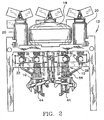
FIG. 3 is a perspective view of one embodiment of a dual-stream filling valve embodying the principles of the present invention, the filling valve including a hoop assembly and valve ball arrangement, the valve being illustrated with an exemplary universal product valve mounted atop the dual stream valve, and further illustrated with the outer, primary filling tube removed for clarity of illustration; -
FIGS. 4a and 4b are partial cross-sectional front and side views, respectively, of the dual-stream filling valve ofFIG. 3 , with the primary filling tube in place, and with the valve in the closed position; -
FIGS. 5a and 5b are partial cross-sectional side views of the dual-stream valve, similar toFIG. 4b but with the primary tube removed, showing the valve in the closed position and opened position inFIGS. 5a and 5b , respectively; -
FIGS. 6a and 6b illustrate another embodiment of the dual-stream valve embodying the principles of the present invention, the valve being shown in the opened and closed positions, respectively; - FIG 8 is a side view of an exemplary valve plug or cone that can be used with the embodiment of the valve shown in
FIGS. 6a and 6b . - With reference now to the figures and in particular to
FIGS. 2-4 , there is shown one embodiment of a dual-stream filling valve 10 embodying the principles of the present invention. Thevalve 10 is illustrated installed within a fillingapparatus 12. As noted above, theapparatus 12 may be used for packaging flowable materials, such as both skim milk and cream in a single container to produce milk having a specific, e.g., 2%, milk fat content. For purposes of the present discussion, the flow path for the skim milk will be referred to as the primary material or fill path, indicated at 14, and the flow path for the cream will be referred to as the secondary material or fill path, indicated at 16. The components within the primary andsecondary fill paths -
FIG. 1 illustrates, schematically, theapparatus 12.FIG. 2 is one physical arrangement of such anapparatus 12. Theapparatus 12 includes, generally, a primary product or material reservoir orstorage tank 18, asecondary reservoir 20, primary and secondary material pumps, 22, 24, respectively, for the primary and secondary materials, and primary and secondarymaterial transfer connections pumps stream valve 10. Theprimary flow path 14 may include aresuction valve 30 that absorbs any pressure increase or spike as the flow of material into a container is terminated. This prevents the material from dripping or dropping during the periods following flow termination and between periods of material flow. - In a typical arrangement, the
apparatus 12 components includeflanges 32 that are clamped or connected to one another by dairy clamps 34. Theflanges 32 may include seal elements, such as O-rings 36, to facilitate maintaining a seal between the components in the fill or flowpaths - The
valve 10 includes primary and secondary, i.e., outer and inner concentrically disposed product transfer or fillingtubes primary transfer tube 38 may carry, for example, skim milk, from theprimary storage tank 18, while the inner orsecondary tube 40 may carry, for example, cream from thesecondary tank 20. In the present arrangement, the flowable materials can be mixed immediately prior to and as they are introduced into a common container. That is, the primary and secondary materials are mixed at about the discharge end 42 of the primarytube filling tube 38. Alternately, one of the materials can be first introduced into the container with the other material introduced subsequent thereto. - Various combinations of materials are intended to be produced using the
present apparatus 12. For example, the primary and secondary storage tanks, 18, 20 can contain skim milk and whole milk, respectively, to produce the desired end product. Alternately, the material in the tanks, 18, 20 can be interchanged to produce other desired products. Also, as provided above, it is contemplated that other, non-liquid and partially-liquid flowable materials as well as combinations thereof, can be packaged using thepresent filling apparatus 12. Reference herein to flowable material, material, flowable product, product, and the like, shall be construed to include all such liquid, non-liquid and partially-liquid flowable materials, including both food products and non-food products. - Those skilled in the art will recognize that the
primary filling tube 38 includes a fillingnozzle 44 at the discharge end 42 thereof. Thenozzle 44 conforms to the size and shape of the container that is being filled, as the flowable material exits thenozzle 44. Typically,such nozzles 44 are formed of a pliable material, such as a food grade, e.g., FDA approved, silicone rubber, and are configured to open outward to conform to the container opening upon initiation of product flow and to fold inward upon termination of product flow. The inward folding of thenozzle 44 minimizes any dripping or dropping of material from thetube 38 between filling of containers. - Referring now to
FIGS. 3-5 , theprimary filling tube 38 has amain body portion 46 defining theflow path 14 through which the primary material flows from thepump 22 to thenozzle 44. Thebody 46 includes a secondary tube opening orpenetration 48 therein that is positioned intermediate theprimary tube 38 inlet and discharge ends, 50, 42, respectively, and is configured to receive thesecondary tube 40. Thepenetration 48 is sealed about thesecondary tube 40 to isolate theflow path 14 from the environs. - The
secondary tube 40 has valve means 54 associated therewith. The valve means 54 and thesecondary tube 40 move, at least in part, relative to one another to establish or initiate and terminate flow of the secondary material from thesecondary tube 40. Thevalve 54 can include, for example, a valve cone, such as a valve ball or plug. The valve means 54 lies in thematerial flow path 16. When thevalve 54 is in the opened position or state, flow communication is established between the primary andsecondary filling tubes secondary tube 40 to theprimary tube 38. Conversely, when thevalve 54 is in the closed position or state, flow communication, and thus material or product flow, between the primary andsecondary tubes - In one embodiment, as best seen in
FIGS. 3-5 , the primary andsecondary filling tubes secondary tube 40 is fixedly mounted to theprimary tube body 46. The valve means 54 includes anactuator 56 having avalve lever 58 that penetrates theprimary tube body 46 at apenetration 59 that is intermediate thesecondary penetration 48 and theinlet end 50 of theprimary tube 38. Thevalve lever 58 extends into the primarytube flow region 60 and pivots generally longitudinally along theflow path 14. Thelever 58 is positioned and pivots within a sleeve-like element 62 that extends from a diaphragm seal 64, into theprimary flow path 14. The seal 64 andsleeve 62 isolate the portion of thelever 58 internal to theprimary tube 38, and thus the primary material from the environs. - The
lever 58 is operably connected to the valve means 54 to establish and terminate flow from thesecondary filling tube 40. In a current embodiment, the valve means 54 is avalve ball 66 that is operably connected to thelever 58 by a actuatingrod assembly 68. Thevalve ball 66 is formed of a polymeric material, such as the aforementioned silicone. Silicone has been found to be an ideal material for this application because of its ability to conform to thetube 40 opening thus creating a liquid-tight or material-tight seal, and because of its hygienic, e.g., clean-ability, characteristics. - The
rod assembly 68 can include arectangular hoop 70 that extends along two sides, or 180° about thesecondary filling tube 40, as seen inFIGS. 3-4 , and can include J-shapedmembers 72 that extend from thebase 74 of thehoop 70, essentially forming arod cage 76. Thecage 76 is configured to essentially "ride" along the outside of thesecondary tube 40. A distance or gap of about 1/4 mm between therods tube 40 is anticipated to be sufficient to prevent binding of the rods, 70, 72, andtube 40, while permitting free, guided movement of therods valve ball 66 is surrounded at 90° intervals by therod cage 76, and theball 66 can freely rotate within thecage 76. - Advantageously, permitting the
ball 66 to freely rotate enhances the ability of theball 66 to seal thesecondary tube 40. Because theball 66 rotates, the area of theball 66 that is subject to compression against the secondarytube discharge end 78 will likely change from one compression to the next. Thus, free rotation of theball 66 distributes compression on theball 66 over more of the surface of theball 66 and subjects it to less localized wear as a result of the continuous compression of the softer,resilient ball 66 against thesecondary tube 40. Moreover, it is contemplated that free rotation of theball 66 will increase the ability of theball 66 to "self-clean." That is, there will be less accumulation or build-up of product on theball 66, thus reducing the opportunity for improper seating of theball 66 at thetube discharge end 78. - The
rod assembly 68 includes a connectingmember 80 that is adapted to receive thelever 58. The connectingmember 80 andlever 58 are configured such that, as thelever 58 is pivoted, therod cage 76 is moved toward and away from the secondarytube discharge end 78. As thecage 76 is moved toward and away from thedischarge end 78, theball 66 seats and unseats from thetube 40. - Advantageously, the
valve ball 66 is also self aligning. That is, even if theball 66 is slightly off of center as it is brought into contact withtube 40, the spherical shape of theball 66 will cause it to shift or move into alignment with thedischarge end 78 and form a seal thereacross. Other valve cone shapes and valve types, such as those disclosed herein, as well as standard plugs or plug-cocks, truncated plug-cocks, flap-type valves and the like can also be used with therod assembly 68 arrangement. Such other shapes and configurations of valve plugs are within the scope of the present invention. - The
lever 58 is actuated by anexternal drive 82 that is isolated from the flowable material. In this manner, the hygienic standards of the "wetted" or "contacted"apparatus 12 components can be more readily maintained if necessary or desired. This is particularly suitable for use of theapparatus 12 in packaging food products or the like. The manner of actuating thelever 58 can include mechanical drives, electro-mechanical drives, hydraulic and pneumatic drives. Such drives, and their use and application, will be readily recognized by those skilled in the art. - As is apparent from the figures and the above description of this embodiment of the dual-
stream filling valve 10, the primary andsecondary filling tubes valve ball 66 andsecondary tube 40 move relative to one another. This arrangement provides avalve ball 66 that is readily accessible for maintenance and inspection by removing the mechanical components of the actuatingassembly 68. - An alternate embodiment of the dual-
stream filling valve 110 is illustrated inFIGS. 6a and 6b . In this embodiment, theprimary tube 112 includes first and second, e.g., upper and lowerstationary body portions intermediate housing portion 118 positioned between the upper andlower body portions intermediate housing 118, which includes an opening orpenetration 120 for thesecondary tube 122, reciprocates between, and relative to, the upper andlower body portions valve cone 126, is fixedly mounted to one of thestationary body portions lower body portion 116. - With reference to
FIGS. 6a and 6b , as theintermediate housing 118 reciprocates, thesecondary tube 122 likewise reciprocates, and is moved into and out of contact with thevalve cone 126. For example, when theintermediate housing 118 is moved downward (FIG. 6b ), toward thedischarge end 128 of theprimary tube 112, thesecondary tube 122 moves into contact with thevalve cone 126, and the flow of material therefrom is terminated. Conversely, when theintermediate housing 118 is moved upwardly (FIG. 6a ), toward theinlet end 130 of theprimary tube 112, thesecondary tube 122 is moved out of contact with thevalve cone 126. In this position, thevalve 124 is open, thus establishing flow communication between the primary andsecondary tubes - The
upper body portion 114 andintermediate housing 118 and theintermediate housing 118 andlower body portion 116 are connected to one another by cooperating, moving connectors orjoints joints intermediate housing 118 to reciprocate relative to and between the fixed upper andlower body portions secondary filling tube 122 fixedly mounted to theintermediate housing 118, thesecondary tube 122 likewise reciprocates relative to the upper andlower body portions - As best seen in
FIGS. 6a and 6b , each slidingconnector inner slide member outer slide member inner slide members outer members outer members end wall 136 to prevent theinner members outer members - The sliding
members seal elements 138, such as the illustrated flexible diaphragms. Thediaphragms 138 flex as thejoints diaphragms 138 are retained in place by rings orlips 144 integral with thediaphragms 138 that are positioned ingrooves 146 formed in theflanges 148. As theflanges 148 are compressed together, thediaphragms 138 are secured in place. - In a typical arrangement, as discussed above, the components are clamped together at the
flanges 148 by dairy clamps (seeclamp 34 inFIG. 3 ). Theclamps 34 maintain the components of theapparatus 12 rigid and the material flow path isolated from the environs. Thediaphragm 138, like thevalve nozzle 150 is formed of a food-grade material, such as silicone rubber. Thediaphragm 138 material is formulated with sufficient elasticity so that thediaphragm 138 will withstand repeated and continuous flexing as theintermediate housing 118 andsecondary filling tube 122 are reciprocated. Thus, the hygienic standards that may be required or desired for the process can be readily achieved and maintained, while isolating the movingconnectors -
FIGS. 6a and 6b illustrate thevalve 110 with the valve in the opened and closed positions, respectively. As is apparent from the figures, thejoints intermediate housing 118 to reciprocate within a fixed linear space. Thus, when one of the joints, for example the upper joint 132, is in the extended position (as shown inFIG. 6b ), the other joint 134, is in the retracted position. In this manner, both joints' 132, 134 likemembers members valve 110. In a current embodiment, theintermediate housing 118 reciprocates between about 10 millimeters (mm) and 13mm, from the top of stroke or opened position as shown inFIG. 6a , to the bottom of stroke or closed position as shown inFIG. 6b . - An
exemplary valve cone 126 is illustrated in place in thevalve 110 inFIGS. 6a and 6b . Thecone 126 is a resilient member that is formed of, for example, a silicone rubber, similar to the other non-metallic, wetted, silicone components. Thevalve cone 126 is supported in place in theprimary flow chamber 152 by a plurality ofrigid support elements 154 that extend inwardly from the inside surface of theprimary filling tube 112. Theelements 154 are positioned about the primarytube flow chamber 152 so as to minimize interfering with the flowing material. - In one embodiment, the
cone 126 includes guide means 156 to maintain thecone 126 in alignment with thesecondary tube 122. The guide means can include theribs 156 as shown on thecone 126 ofFIGS. 6a and 6b , to facilitate proper seating of the reciprocatingsecondary tube 122 with thecone 126. - Another
exemplary cone 170, referred to as a V-groove cone 170, is shown in detail inFIG. 7 , the V-groove valve cone 170 includes a cylindrical, barrel-likemain body portion 172. Thecone 170 has a plurality of V-shaped, angled grooves as indicated at 174 formed in thebody 172. The angling of eachgroove 174 is such that the cross-sectional area of thegroove 174 is greatest at the top 176 of thecone 170 and decreases downward, along the length l of thecone 170 and thegroove 174. Thegrooves 174 have a V-shape as viewed from the front and sides 178,180 of the cone as seen inFIG. 7 , and as seen from the top 176 of thecone 170. Alternately, thegrooves 174, as viewed from the top 176 of thecone 170, can have a curvilinear cross-section, such as quarter-circular, semicircular and parabolic shaped cross-sections. All such cross-sectional shapes are within the scope of the present invention. - It has been observed that such a V-
groove 174 configuration provides enhanced flow control characteristics. In the illustrated V-groove configuration 174, thecone 170 resides within thedischarge end 158 of thesecondary tube 122, when in the closed position, thus maintaining alignment of thecone 170 andtube 122. Thecone 170 includes guide or alignment means to maintain thecone 170 in alignment with thesecondary tube 122 as they are engaged with one another. Such guide means can be internal to thetube 122 or external to thecone 170. - In the
cone 126 illustrated inFIGS. 6a and 6b , alignment of thecone 126 andtube 122 is effected by theribs 156 that extend outwardly from thecone 170. Alternately, as shown in thecone 170 ofFIG. 7 , alignment can be maintained by a beveled edge orchamber 182 along the top 126 andsides 180 of thecone 170. Those skilled in the art will recognize the various means that can be used to maintain alignment of thesecondary tube 122 and these cone 126,170 configurations, as well as other cone configurations. - The
intermediate housing 122 can be reciprocated by any of a variety of drive means 160, including mechanical drives, electro-mechanical drives, hydraulic and pneumatic drives. Such drives, and their use and application, will be readily recognized by those skilled in the art. The use of all such drives are within the scope of the present invention as defined by the appended claims.
Claims (10)
- A dual stream fill system for a packaging machine, having a primary fill tube (38) with an inlet (50) and a discharge end (42) for introducing a first flowable food into a container; and a secondary fill tube (40) extending concentrically within the primary fill tube for introducing a second flowable food into the container through an outlet (78); and a valve mechanism (54) for controlling the flow of second flowable product from the secondary fill tube (40),
CHARACTERISED IN THAT
the secondary fill tube (40) includes a section which penetrates the primary tube (38) through a first opening intermediate the inlet and discharge ends of the primary tube, and the valve mechanism (54) is controlled by an actuator (68) within the primary fill tube (38) but wholly external of the secondary tube (40), the valve mechanism including an actuating lever (58) extending at least in part through a second opening (64) in the primary fill tube (38). - A fill system according to any preceding Claim wherein the valve mechanism (54) is movable relative to both the primary fill tube (38) and the secondary fill tube (40).
- A fill system according to any preceding Claim wherein the valve mechanism (54) includes a caged rod assembly with at valve ball (66) therein, the valve ball in its closed position blacking the outlet from the secondary tube (40).
- A fill system according to any preceding Claim wherein the actuator (68) is disposed in part intermediate the primary and secondary fill tubes (38,40) and in part external to the primary fill tube (38) and pivotable to move the valve mechanism (54) between open and closed positions.
- A fill system according to Claim 4 wherein the actuator (68) is operable connected to a rod hoop (70) adapted to support a valve ball (66) and move the ball into and out of engagement with the secondary fill tube outlet (78) at at least 180 degree intervals.
- A dual stream fill system for a packaging machine, having a primary fill tube (112) with an inlet (50) and a discharge end (42) for introducing a first flowable food into a container; and a secondary fill tube (122) extending concentrically within the primary fill tube for introducing a second flowable food into the container through an outlet (158); and a valve mechanism (124) for controlling the flow of second flowable product from the secondary fill tube (122),
CHARACTERISED IN THAT
the secondary fill tube (122) includes a section which penetrates the primary fill tube (112) through a first opening intermediate the inlet and discharge ends of the primary fill tube, and the valve mechanism (124) is controlled by an actuator (68) within the primary fill tube (112) but wholly external of the secondary fill tube (112), wherein the primary fill tube (112) includes a stationary upper body portion (114), a stationary lower body portion (116) and an intermediate housing portion (118) disposed between and operably connected to the upper and lower body portions by respective first and second cooperating joints (132,134), and wherein the secondary fill tube (122) penetrates the primary fill tube (112) at the intermediate housing and is movable relative to the upper and lower body portions (114,116) by movement of the cooperating joints. - A fill system according to Claim 6, wherein the cooperating joints (132,134) reciprocate generally collinearly relative to the flow path of the first and second flowable foods.
- A fill system according to Claim 6 or Claim 7 wherein a diaphragm (138) extends about the cooperating joints to isolate the flowable foods from the joints.
- A fill system according to any of Claims 6 to 8 wherein the valve mechanism (124) includes a valve cone (126).
- A fill system according to Claim 9 wherein the valve cone (126) has at least one V-groove (174) therein extending along a length of the cone from a top of the cone downward, and having a cross-sectional area that decreases along the length of the cone.
Applications Claiming Priority (3)
| Application Number | Priority Date | Filing Date | Title |
|---|---|---|---|
| US897554 | 1986-08-18 | ||
| US08/897,554 US5829476A (en) | 1997-07-21 | 1997-07-21 | Dual-stream filling valve |
| PCT/US1998/013142 WO1999003773A1 (en) | 1997-07-21 | 1998-06-23 | Dual-stream filling valve |
Publications (2)
| Publication Number | Publication Date |
|---|---|
| EP1015379A1 EP1015379A1 (en) | 2000-07-05 |
| EP1015379B1 true EP1015379B1 (en) | 2012-08-15 |
Family
ID=25408045
Family Applications (1)
| Application Number | Title | Priority Date | Filing Date |
|---|---|---|---|
| EP19980931557 Expired - Lifetime EP1015379B1 (en) | 1997-07-21 | 1998-06-23 | Dual-stream filling valve |
Country Status (7)
| Country | Link |
|---|---|
| US (3) | US5829476A (en) |
| EP (1) | EP1015379B1 (en) |
| JP (2) | JPH1149291A (en) |
| AU (1) | AU8165798A (en) |
| DK (1) | DK1015379T3 (en) |
| NO (1) | NO317769B1 (en) |
| WO (1) | WO1999003773A1 (en) |
Families Citing this family (21)
| Publication number | Priority date | Publication date | Assignee | Title |
|---|---|---|---|---|
| US6092568A (en) * | 1997-07-21 | 2000-07-25 | Tetra Laval Holdings & Finance, Sa | Product valve complex for dual stream filling system |
| IT1311025B1 (en) * | 1999-01-18 | 2002-02-28 | Uni Mac S R L | AUTOMATIC WEIGHT FILLER WITH TOTAL CLEANING SYSTEM BY SCRAPING. |
| US6390513B1 (en) * | 1999-10-04 | 2002-05-21 | Tetra Laval Holdings & Finance, Sa | Collapsible spacer pipe |
| IL160417A (en) * | 2004-02-16 | 2011-04-28 | Mosaid Technologies Inc | Outlet add-on module |
| CN100546878C (en) * | 2005-02-23 | 2009-10-07 | 诺登机械公司 | filling nozzle |
| US8046976B2 (en) | 2006-07-25 | 2011-11-01 | The Coca-Cola Company | Devices and methods for packaging beverages |
| DE102008010078A1 (en) * | 2008-02-19 | 2009-09-17 | Khs Ag | A method for filling containers with a consisting of at least two components filling, filling and filling machine for performing the method |
| DE102009013080A1 (en) * | 2009-03-13 | 2010-09-23 | Benz & Hilgers Gmbh | Method for packaging portioned pasty product i.e. emulsion, involves portioning product in pasty condition, and homogenizing directly product in pasty condition before transferring product into packaging and after portioning product |
| CN101590993B (en) * | 2009-03-16 | 2012-09-05 | 杭州中亚机械股份有限公司 | Aseptic filling valve |
| DE102009032795A1 (en) * | 2009-07-10 | 2011-01-13 | Krones Ag | Filling device for filling containers |
| DE102009032791A1 (en) * | 2009-07-10 | 2011-01-13 | Krones Ag | Device for filling multi-component drinks |
| CN102616717A (en) * | 2012-04-07 | 2012-08-01 | 浙江炜驰轻工机械有限公司 | Filling valve of filling and can sealing integrated machine |
| CN105752916B (en) * | 2016-04-05 | 2018-06-29 | 袁静 | A kind of multichannel irrigation flow adjuster for blueberry wine bottle placer |
| CN110500425B (en) * | 2019-07-26 | 2021-05-11 | 上海卫星装备研究所 | A kind of multi-layer high vacuum flap valve system and using method thereof |
| US10766051B1 (en) * | 2019-08-06 | 2020-09-08 | Max Lee Horton | Apparatuses for wetting mildew-removal strips and related methods |
| CN113120312A (en) * | 2020-01-07 | 2021-07-16 | 杭州伊尹健康技术有限公司 | Multi-nozzle output type Chinese medicine filling mechanism not easy to generate splashing phenomenon during filling Chinese medicine |
| CN110980617B (en) * | 2020-01-07 | 2021-06-08 | 杭州伊尹健康技术有限公司 | An energy-reducing type traditional Chinese medicine transportation pipeline |
| CN110980616B (en) * | 2020-01-07 | 2021-07-30 | 杭州伊尹健康技术有限公司 | Traditional Chinese medicine filling method |
| CN111003678B (en) * | 2020-01-07 | 2021-06-08 | 杭州伊尹健康技术有限公司 | Impact reducing method for vertical conveying of traditional Chinese medicine solution |
| CN112897433B (en) * | 2021-01-14 | 2022-07-29 | 高秀真 | Liquid medicine partial shipment processing apparatus for internal medicine nursing |
| CN113955697B (en) * | 2021-11-25 | 2023-02-28 | 华夏生生药业(北京)有限公司 | Liquid medicine configuration system |
Family Cites Families (29)
| Publication number | Priority date | Publication date | Assignee | Title |
|---|---|---|---|---|
| NL273312A (en) * | ||||
| US2134200A (en) * | 1935-11-04 | 1938-10-25 | Felix L Pivoto | Plug valve casing head |
| US2325242A (en) * | 1941-01-24 | 1943-07-27 | Gordon Arthur | Mixing unit |
| US2316781A (en) * | 1941-02-12 | 1943-04-20 | Ruth F Barnard | Solution mixing and dispensing device |
| US2537119A (en) * | 1945-02-02 | 1951-01-09 | Dole Valve Co | Liquid dispenser for carbonated beverages |
| US3097764A (en) * | 1960-02-09 | 1963-07-16 | Union Carbide Corp | Proportioning system |
| US3229477A (en) * | 1963-03-04 | 1966-01-18 | Bastian Blessing Co | Ice cream freezer and dispenser |
| US3298383A (en) * | 1964-03-23 | 1967-01-17 | Phillips Petroleum Co | Fluid blending system |
| US3474965A (en) * | 1967-08-28 | 1969-10-28 | Clarence B Coleman | Liquid proportioning and metering pump system |
| US3770208A (en) * | 1970-11-23 | 1973-11-06 | Ethyl Corp | Mixing nozzle |
| DE2241935C3 (en) * | 1972-08-25 | 1981-07-16 | Robert Bosch Gmbh, 7000 Stuttgart | System for exhaust gas decontamination |
| US3876114A (en) * | 1973-02-14 | 1975-04-08 | Artek Ind Inc | Multiple ingredient metering, mixing and dispensing apparatus |
| US4789100A (en) * | 1980-11-04 | 1988-12-06 | Adhesive Engineering Company | Multiple fluid pumping system |
| DE3316130C1 (en) * | 1983-05-03 | 1984-08-02 | Etablissement Dentaire Ivoclar, Schaan | Dental device for the application of powdery polymers |
| US4549676A (en) * | 1983-09-16 | 1985-10-29 | Horst Gerich | Liquid mixing and purging apparatus |
| FR2562053B1 (en) * | 1984-04-03 | 1987-03-06 | Sodima Union Coop Agricoles | INSTALLATION FOR THE AUTOMATIC DISPENSING, ON REQUEST, OF INDIVIDUAL DOSES OF FLAVORED CHOICE OF DRINKING YOGHURT |
| EP0201683A1 (en) * | 1985-05-13 | 1986-11-20 | Jean Egli | A variable colorant blender |
| US4911195A (en) * | 1986-08-27 | 1990-03-27 | Porton Instruments, Inc. | Valve block assembly |
| AT393633B (en) * | 1986-11-26 | 1991-11-25 | Waagner Biro Ag | METHOD FOR MIXING MEDIA OF DIFFERENT TOUGHNESS |
| US5179970A (en) * | 1987-10-23 | 1993-01-19 | The Coca-Cola Company | Beverage dispensing valve |
| US4915688A (en) * | 1987-12-03 | 1990-04-10 | Baxter International Inc. | Apparatus for administering solution to a patient |
| FR2627014B1 (en) * | 1988-02-09 | 1990-07-20 | Oldham France Sa | PROCESS AND APPARATUS FOR FILLING CONTAINERS WITH A GEL COMPOSITION AND THEIR APPLICATION TO ELECTRIC ACCUMULATORS |
| SE466114B (en) * | 1990-05-14 | 1991-12-16 | Tetra Pak Holdings Sa | REGLERKAEGLA |
| US5152461A (en) * | 1990-10-01 | 1992-10-06 | Proctor Rudy R | Hand operated sprayer with multiple fluid containers |
| US5221026A (en) * | 1991-10-15 | 1993-06-22 | Monte Williams | Apparatus for dispensing mixtures of liquids and pressurized gas |
| DE9200647U1 (en) * | 1992-01-21 | 1992-03-19 | Haese, Gerhard, 6501 Stadecken-Elsheim | Liqueur dosage round table filler for sparkling wine production |
| US5188019A (en) * | 1992-03-30 | 1993-02-23 | Vahabpour Abdolvahab K | Automatic tea maker |
| NZ293771A (en) * | 1994-09-29 | 1998-09-24 | Tetra Laval Holdings & Finance | Packaging machine system for filling primary and secondary products into a container |
| DE19535252C2 (en) * | 1995-09-22 | 2001-07-19 | Boehringer Ingelheim Kg | Device and nozzle for filling small amounts of liquid |
-
1997
- 1997-07-21 US US08/897,554 patent/US5829476A/en not_active Expired - Lifetime
- 1997-12-03 JP JP33324297A patent/JPH1149291A/en not_active Withdrawn
-
1998
- 1998-06-23 DK DK98931557.7T patent/DK1015379T3/en active
- 1998-06-23 EP EP19980931557 patent/EP1015379B1/en not_active Expired - Lifetime
- 1998-06-23 AU AU81657/98A patent/AU8165798A/en not_active Abandoned
- 1998-06-23 JP JP2000503015A patent/JP4053237B2/en not_active Expired - Lifetime
- 1998-06-23 WO PCT/US1998/013142 patent/WO1999003773A1/en not_active Ceased
- 1998-09-16 US US09/154,380 patent/US5894845A/en not_active Expired - Lifetime
- 1998-09-16 US US09/154,236 patent/US5896888A/en not_active Expired - Lifetime
-
2000
- 2000-01-20 NO NO20000291A patent/NO317769B1/en not_active IP Right Cessation
Also Published As
| Publication number | Publication date |
|---|---|
| US5894845A (en) | 1999-04-20 |
| JPH1149291A (en) | 1999-02-23 |
| AU8165798A (en) | 1999-02-10 |
| NO20000291L (en) | 2000-03-06 |
| WO1999003773A1 (en) | 1999-01-28 |
| DK1015379T3 (en) | 2012-11-26 |
| EP1015379A1 (en) | 2000-07-05 |
| JP2001510126A (en) | 2001-07-31 |
| NO317769B1 (en) | 2004-12-13 |
| NO20000291D0 (en) | 2000-01-20 |
| JP4053237B2 (en) | 2008-02-27 |
| US5829476A (en) | 1998-11-03 |
| US5896888A (en) | 1999-04-27 |
Similar Documents
| Publication | Publication Date | Title |
|---|---|---|
| US5894845A (en) | Dual-stream filling valve | |
| US5992455A (en) | Dual-stream filling valve | |
| US4436106A (en) | Pipeline switch with leakage control and cleanable leakage cavity | |
| AU679285B2 (en) | Container connection device, fluid dispensing assembly therefor and container provided therewith | |
| KR100743769B1 (en) | Dual component and dual valve trigger sprayer which mixes components in discharge passage | |
| US8578979B2 (en) | Process for dispensing fluid with a slider valve fitment and collar | |
| US6148874A (en) | Filling head mechanism that removes material from a spout of a filled container before completely disengaging from the spout | |
| JP2992636B2 (en) | Valve device for controlling liquid flow | |
| US5816456A (en) | Laminar flow filler spout | |
| US5042694A (en) | Dispenser for pasty compositions | |
| JPH0514150B2 (en) | ||
| KR20060002876A (en) | Dual slider valve accessories | |
| US6953070B1 (en) | Dispenser valve with push-to-open spout | |
| US5108014A (en) | Filling valve | |
| US6484745B1 (en) | Fill valve assembly | |
| EP0093157A1 (en) | CLUTCH AND VALVE UNIT FOR DISPENSING LIQUID. | |
| EP3431187B1 (en) | Device for dispensing a plurality of fluid products | |
| KR102646359B1 (en) | Pneumatically-actuated valve for a machine for the production of liquid or semi-liquid food products and machine comprising the valve | |
| US4844481A (en) | Cylindrical seal system | |
| US6786248B2 (en) | Fill valve assembly for filler device | |
| US20170073208A1 (en) | Filling apparatus | |
| US7156262B2 (en) | Sanitary fill valve assembly with adjustable flow regulator | |
| EP0117329A2 (en) | Fluid dispensing nozzle and feeding apparatus, particularly for a packaging machine | |
| US4846379A (en) | Nozzle assembly for a liquid dispensing machine | |
| EP1392567B1 (en) | Valve assembly for filling containers |
Legal Events
| Date | Code | Title | Description |
|---|---|---|---|
| PUAI | Public reference made under article 153(3) epc to a published international application that has entered the european phase |
Free format text: ORIGINAL CODE: 0009012 |
|
| 17P | Request for examination filed |
Effective date: 20000114 |
|
| AK | Designated contracting states |
Kind code of ref document: A1 Designated state(s): AT BE CH CY DE DK ES FI FR GB GR IE IT LI LU MC NL PT SE |
|
| R17P | Request for examination filed (corrected) |
Effective date: 20000114 |
|
| 17Q | First examination report despatched |
Effective date: 20070816 |
|
| GRAP | Despatch of communication of intention to grant a patent |
Free format text: ORIGINAL CODE: EPIDOSNIGR1 |
|
| RAP1 | Party data changed (applicant data changed or rights of an application transferred) |
Owner name: TETRA LAVAL HOLDINGS & FINANCE S.A. |
|
| GRAS | Grant fee paid |
Free format text: ORIGINAL CODE: EPIDOSNIGR3 |
|
| GRAA | (expected) grant |
Free format text: ORIGINAL CODE: 0009210 |
|
| AK | Designated contracting states |
Kind code of ref document: B1 Designated state(s): AT BE CH CY DE DK ES FI FR GB GR IE IT LI LU MC NL PT SE |
|
| REG | Reference to a national code |
Ref country code: AT Ref legal event code: REF Ref document number: 570710 Country of ref document: AT Kind code of ref document: T Effective date: 20120815 Ref country code: GB Ref legal event code: FG4D Ref country code: CH Ref legal event code: EP |
|
| REG | Reference to a national code |
Ref country code: IE Ref legal event code: FG4D |
|
| REG | Reference to a national code |
Ref country code: DE Ref legal event code: R096 Ref document number: 69842823 Country of ref document: DE Effective date: 20121011 |
|
| REG | Reference to a national code |
Ref country code: SE Ref legal event code: TRGR |
|
| REG | Reference to a national code |
Ref country code: NL Ref legal event code: T3 |
|
| REG | Reference to a national code |
Ref country code: DK Ref legal event code: T3 |
|
| REG | Reference to a national code |
Ref country code: AT Ref legal event code: MK05 Ref document number: 570710 Country of ref document: AT Kind code of ref document: T Effective date: 20120815 |
|
| PG25 | Lapsed in a contracting state [announced via postgrant information from national office to epo] |
Ref country code: AT Free format text: LAPSE BECAUSE OF FAILURE TO SUBMIT A TRANSLATION OF THE DESCRIPTION OR TO PAY THE FEE WITHIN THE PRESCRIBED TIME-LIMIT Effective date: 20120815 Ref country code: CY Free format text: LAPSE BECAUSE OF FAILURE TO SUBMIT A TRANSLATION OF THE DESCRIPTION OR TO PAY THE FEE WITHIN THE PRESCRIBED TIME-LIMIT Effective date: 20120815 |
|
| PG25 | Lapsed in a contracting state [announced via postgrant information from national office to epo] |
Ref country code: GR Free format text: LAPSE BECAUSE OF FAILURE TO SUBMIT A TRANSLATION OF THE DESCRIPTION OR TO PAY THE FEE WITHIN THE PRESCRIBED TIME-LIMIT Effective date: 20121116 Ref country code: BE Free format text: LAPSE BECAUSE OF FAILURE TO SUBMIT A TRANSLATION OF THE DESCRIPTION OR TO PAY THE FEE WITHIN THE PRESCRIBED TIME-LIMIT Effective date: 20120815 Ref country code: PT Free format text: LAPSE BECAUSE OF FAILURE TO SUBMIT A TRANSLATION OF THE DESCRIPTION OR TO PAY THE FEE WITHIN THE PRESCRIBED TIME-LIMIT Effective date: 20121217 |
|
| PG25 | Lapsed in a contracting state [announced via postgrant information from national office to epo] |
Ref country code: ES Free format text: LAPSE BECAUSE OF FAILURE TO SUBMIT A TRANSLATION OF THE DESCRIPTION OR TO PAY THE FEE WITHIN THE PRESCRIBED TIME-LIMIT Effective date: 20121126 |
|
| PG25 | Lapsed in a contracting state [announced via postgrant information from national office to epo] |
Ref country code: IT Free format text: LAPSE BECAUSE OF FAILURE TO SUBMIT A TRANSLATION OF THE DESCRIPTION OR TO PAY THE FEE WITHIN THE PRESCRIBED TIME-LIMIT Effective date: 20120815 |
|
| PLBE | No opposition filed within time limit |
Free format text: ORIGINAL CODE: 0009261 |
|
| STAA | Information on the status of an ep patent application or granted ep patent |
Free format text: STATUS: NO OPPOSITION FILED WITHIN TIME LIMIT |
|
| 26N | No opposition filed |
Effective date: 20130516 |
|
| REG | Reference to a national code |
Ref country code: DE Ref legal event code: R097 Ref document number: 69842823 Country of ref document: DE Effective date: 20130516 |
|
| PG25 | Lapsed in a contracting state [announced via postgrant information from national office to epo] |
Ref country code: MC Free format text: LAPSE BECAUSE OF FAILURE TO SUBMIT A TRANSLATION OF THE DESCRIPTION OR TO PAY THE FEE WITHIN THE PRESCRIBED TIME-LIMIT Effective date: 20120815 |
|
| REG | Reference to a national code |
Ref country code: CH Ref legal event code: PL |
|
| GBPC | Gb: european patent ceased through non-payment of renewal fee |
Effective date: 20130623 |
|
| REG | Reference to a national code |
Ref country code: IE Ref legal event code: MM4A |
|
| REG | Reference to a national code |
Ref country code: FR Ref legal event code: ST Effective date: 20140228 |
|
| PG25 | Lapsed in a contracting state [announced via postgrant information from national office to epo] |
Ref country code: CH Free format text: LAPSE BECAUSE OF NON-PAYMENT OF DUE FEES Effective date: 20130630 Ref country code: GB Free format text: LAPSE BECAUSE OF NON-PAYMENT OF DUE FEES Effective date: 20130623 Ref country code: LI Free format text: LAPSE BECAUSE OF NON-PAYMENT OF DUE FEES Effective date: 20130630 Ref country code: IE Free format text: LAPSE BECAUSE OF NON-PAYMENT OF DUE FEES Effective date: 20130623 |
|
| PG25 | Lapsed in a contracting state [announced via postgrant information from national office to epo] |
Ref country code: FR Free format text: LAPSE BECAUSE OF NON-PAYMENT OF DUE FEES Effective date: 20130701 |
|
| PG25 | Lapsed in a contracting state [announced via postgrant information from national office to epo] |
Ref country code: LU Free format text: LAPSE BECAUSE OF NON-PAYMENT OF DUE FEES Effective date: 20130623 |
|
| PGFP | Annual fee paid to national office [announced via postgrant information from national office to epo] |
Ref country code: FI Payment date: 20160609 Year of fee payment: 19 Ref country code: DE Payment date: 20160614 Year of fee payment: 19 |
|
| PGFP | Annual fee paid to national office [announced via postgrant information from national office to epo] |
Ref country code: SE Payment date: 20160613 Year of fee payment: 19 Ref country code: DK Payment date: 20160610 Year of fee payment: 19 Ref country code: NL Payment date: 20160610 Year of fee payment: 19 |
|
| REG | Reference to a national code |
Ref country code: DE Ref legal event code: R119 Ref document number: 69842823 Country of ref document: DE |
|
| REG | Reference to a national code |
Ref country code: DK Ref legal event code: EBP Effective date: 20170630 |
|
| REG | Reference to a national code |
Ref country code: SE Ref legal event code: EUG |
|
| PG25 | Lapsed in a contracting state [announced via postgrant information from national office to epo] |
Ref country code: FI Free format text: LAPSE BECAUSE OF NON-PAYMENT OF DUE FEES Effective date: 20170623 |
|
| REG | Reference to a national code |
Ref country code: NL Ref legal event code: MM Effective date: 20170701 |
|
| PG25 | Lapsed in a contracting state [announced via postgrant information from national office to epo] |
Ref country code: SE Free format text: LAPSE BECAUSE OF NON-PAYMENT OF DUE FEES Effective date: 20170624 |
|
| PG25 | Lapsed in a contracting state [announced via postgrant information from national office to epo] |
Ref country code: NL Free format text: LAPSE BECAUSE OF NON-PAYMENT OF DUE FEES Effective date: 20170701 |
|
| PG25 | Lapsed in a contracting state [announced via postgrant information from national office to epo] |
Ref country code: DE Free format text: LAPSE BECAUSE OF NON-PAYMENT OF DUE FEES Effective date: 20180103 |
|
| PG25 | Lapsed in a contracting state [announced via postgrant information from national office to epo] |
Ref country code: DK Free format text: LAPSE BECAUSE OF NON-PAYMENT OF DUE FEES Effective date: 20170630 |