EP1015123B1 - Apparatus for cleaning a suspension, preferably a fiber mass suspension - Google Patents
Apparatus for cleaning a suspension, preferably a fiber mass suspension Download PDFInfo
- Publication number
- EP1015123B1 EP1015123B1 EP98945333A EP98945333A EP1015123B1 EP 1015123 B1 EP1015123 B1 EP 1015123B1 EP 98945333 A EP98945333 A EP 98945333A EP 98945333 A EP98945333 A EP 98945333A EP 1015123 B1 EP1015123 B1 EP 1015123B1
- Authority
- EP
- European Patent Office
- Prior art keywords
- space
- suspension
- receptacle
- partition wall
- aeration
- Prior art date
- Legal status (The legal status is an assumption and is not a legal conclusion. Google has not performed a legal analysis and makes no representation as to the accuracy of the status listed.)
- Expired - Lifetime
Links
- 239000000725 suspension Substances 0.000 title claims abstract description 100
- 239000000835 fiber Substances 0.000 title claims abstract description 39
- 238000004140 cleaning Methods 0.000 title claims abstract description 14
- 238000005192 partition Methods 0.000 claims abstract description 99
- 238000005273 aeration Methods 0.000 claims abstract description 52
- 239000012535 impurity Substances 0.000 claims abstract description 18
- 238000007599 discharging Methods 0.000 claims abstract description 3
- 238000004891 communication Methods 0.000 claims description 6
- 239000000126 substance Substances 0.000 claims description 3
- 238000000034 method Methods 0.000 description 3
- 238000007639 printing Methods 0.000 description 2
- 230000000630 rising effect Effects 0.000 description 2
- 125000006850 spacer group Chemical group 0.000 description 2
- 241000252254 Catostomidae Species 0.000 description 1
- 238000009825 accumulation Methods 0.000 description 1
- 239000002761 deinking Substances 0.000 description 1
- 238000005188 flotation Methods 0.000 description 1
- 238000012423 maintenance Methods 0.000 description 1
- 239000002245 particle Substances 0.000 description 1
- 230000001902 propagating effect Effects 0.000 description 1
- 238000005086 pumping Methods 0.000 description 1
- 238000004064 recycling Methods 0.000 description 1
- 238000007790 scraping Methods 0.000 description 1
- 238000000926 separation method Methods 0.000 description 1
- 239000007787 solid Substances 0.000 description 1
Images

Classifications
-
- B—PERFORMING OPERATIONS; TRANSPORTING
- B03—SEPARATION OF SOLID MATERIALS USING LIQUIDS OR USING PNEUMATIC TABLES OR JIGS; MAGNETIC OR ELECTROSTATIC SEPARATION OF SOLID MATERIALS FROM SOLID MATERIALS OR FLUIDS; SEPARATION BY HIGH-VOLTAGE ELECTRIC FIELDS
- B03D—FLOTATION; DIFFERENTIAL SEDIMENTATION
- B03D1/00—Flotation
- B03D1/14—Flotation machines
- B03D1/24—Pneumatic
- B03D1/26—Air lift machines
-
- B—PERFORMING OPERATIONS; TRANSPORTING
- B03—SEPARATION OF SOLID MATERIALS USING LIQUIDS OR USING PNEUMATIC TABLES OR JIGS; MAGNETIC OR ELECTROSTATIC SEPARATION OF SOLID MATERIALS FROM SOLID MATERIALS OR FLUIDS; SEPARATION BY HIGH-VOLTAGE ELECTRIC FIELDS
- B03D—FLOTATION; DIFFERENTIAL SEDIMENTATION
- B03D1/00—Flotation
- B03D1/14—Flotation machines
- B03D1/1443—Feed or discharge mechanisms for flotation tanks
-
- B—PERFORMING OPERATIONS; TRANSPORTING
- B03—SEPARATION OF SOLID MATERIALS USING LIQUIDS OR USING PNEUMATIC TABLES OR JIGS; MAGNETIC OR ELECTROSTATIC SEPARATION OF SOLID MATERIALS FROM SOLID MATERIALS OR FLUIDS; SEPARATION BY HIGH-VOLTAGE ELECTRIC FIELDS
- B03D—FLOTATION; DIFFERENTIAL SEDIMENTATION
- B03D1/00—Flotation
- B03D1/001—Flotation agents
-
- B—PERFORMING OPERATIONS; TRANSPORTING
- B03—SEPARATION OF SOLID MATERIALS USING LIQUIDS OR USING PNEUMATIC TABLES OR JIGS; MAGNETIC OR ELECTROSTATIC SEPARATION OF SOLID MATERIALS FROM SOLID MATERIALS OR FLUIDS; SEPARATION BY HIGH-VOLTAGE ELECTRIC FIELDS
- B03D—FLOTATION; DIFFERENTIAL SEDIMENTATION
- B03D1/00—Flotation
- B03D1/14—Flotation machines
- B03D1/1412—Flotation machines with baffles, e.g. at the wall for redirecting settling solids
-
- B—PERFORMING OPERATIONS; TRANSPORTING
- B03—SEPARATION OF SOLID MATERIALS USING LIQUIDS OR USING PNEUMATIC TABLES OR JIGS; MAGNETIC OR ELECTROSTATIC SEPARATION OF SOLID MATERIALS FROM SOLID MATERIALS OR FLUIDS; SEPARATION BY HIGH-VOLTAGE ELECTRIC FIELDS
- B03D—FLOTATION; DIFFERENTIAL SEDIMENTATION
- B03D1/00—Flotation
- B03D1/14—Flotation machines
- B03D1/1493—Flotation machines with means for establishing a specified flow pattern
-
- B—PERFORMING OPERATIONS; TRANSPORTING
- B03—SEPARATION OF SOLID MATERIALS USING LIQUIDS OR USING PNEUMATIC TABLES OR JIGS; MAGNETIC OR ELECTROSTATIC SEPARATION OF SOLID MATERIALS FROM SOLID MATERIALS OR FLUIDS; SEPARATION BY HIGH-VOLTAGE ELECTRIC FIELDS
- B03D—FLOTATION; DIFFERENTIAL SEDIMENTATION
- B03D1/00—Flotation
- B03D1/14—Flotation machines
- B03D1/16—Flotation machines with impellers; Subaeration machines
-
- B—PERFORMING OPERATIONS; TRANSPORTING
- B03—SEPARATION OF SOLID MATERIALS USING LIQUIDS OR USING PNEUMATIC TABLES OR JIGS; MAGNETIC OR ELECTROSTATIC SEPARATION OF SOLID MATERIALS FROM SOLID MATERIALS OR FLUIDS; SEPARATION BY HIGH-VOLTAGE ELECTRIC FIELDS
- B03D—FLOTATION; DIFFERENTIAL SEDIMENTATION
- B03D1/00—Flotation
- B03D1/14—Flotation machines
- B03D1/24—Pneumatic
-
- B—PERFORMING OPERATIONS; TRANSPORTING
- B03—SEPARATION OF SOLID MATERIALS USING LIQUIDS OR USING PNEUMATIC TABLES OR JIGS; MAGNETIC OR ELECTROSTATIC SEPARATION OF SOLID MATERIALS FROM SOLID MATERIALS OR FLUIDS; SEPARATION BY HIGH-VOLTAGE ELECTRIC FIELDS
- B03D—FLOTATION; DIFFERENTIAL SEDIMENTATION
- B03D1/00—Flotation
- B03D1/14—Flotation machines
- B03D1/24—Pneumatic
- B03D1/242—Nozzles for injecting gas into the flotation tank
-
- D—TEXTILES; PAPER
- D21—PAPER-MAKING; PRODUCTION OF CELLULOSE
- D21B—FIBROUS RAW MATERIALS OR THEIR MECHANICAL TREATMENT
- D21B1/00—Fibrous raw materials or their mechanical treatment
- D21B1/04—Fibrous raw materials or their mechanical treatment by dividing raw materials into small particles, e.g. fibres
- D21B1/12—Fibrous raw materials or their mechanical treatment by dividing raw materials into small particles, e.g. fibres by wet methods, by the use of steam
- D21B1/30—Defibrating by other means
- D21B1/32—Defibrating by other means of waste paper
- D21B1/325—Defibrating by other means of waste paper de-inking devices
-
- D—TEXTILES; PAPER
- D21—PAPER-MAKING; PRODUCTION OF CELLULOSE
- D21C—PRODUCTION OF CELLULOSE BY REMOVING NON-CELLULOSE SUBSTANCES FROM CELLULOSE-CONTAINING MATERIALS; REGENERATION OF PULPING LIQUORS; APPARATUS THEREFOR
- D21C5/00—Other processes for obtaining cellulose, e.g. cooking cotton linters ; Processes characterised by the choice of cellulose-containing starting materials
- D21C5/02—Working-up waste paper
-
- D—TEXTILES; PAPER
- D21—PAPER-MAKING; PRODUCTION OF CELLULOSE
- D21F—PAPER-MAKING MACHINES; METHODS OF PRODUCING PAPER THEREON
- D21F1/00—Wet end of machines for making continuous webs of paper
- D21F1/66—Pulp catching, de-watering, or recovering; Re-use of pulp-water
- D21F1/70—Pulp catching, de-watering, or recovering; Re-use of pulp-water by flotation
-
- Y—GENERAL TAGGING OF NEW TECHNOLOGICAL DEVELOPMENTS; GENERAL TAGGING OF CROSS-SECTIONAL TECHNOLOGIES SPANNING OVER SEVERAL SECTIONS OF THE IPC; TECHNICAL SUBJECTS COVERED BY FORMER USPC CROSS-REFERENCE ART COLLECTIONS [XRACs] AND DIGESTS
- Y02—TECHNOLOGIES OR APPLICATIONS FOR MITIGATION OR ADAPTATION AGAINST CLIMATE CHANGE
- Y02W—CLIMATE CHANGE MITIGATION TECHNOLOGIES RELATED TO WASTEWATER TREATMENT OR WASTE MANAGEMENT
- Y02W30/00—Technologies for solid waste management
- Y02W30/50—Reuse, recycling or recovery technologies
- Y02W30/64—Paper recycling
Definitions
- the invention relates to an apparatus for cleaning a suspension, preferably a fiber mass suspension, the apparatus comprising a receptacle, into which the suspension to be cleaned and necessary chemicals are fed, an inlet channel and an outlet channel for feeding the suspension into and for discharging it from the receptacle, respectively, means for feeding air into the suspension, at least one partition wall for dividing the receptacle into two separate spaces and means for removing impurities, separated along with air bubbles on the surface of the suspension, from the receptacle.
- GB Patent 2 291 367 discloses a solution, in which a suspension is fed into a circular receptacle divided into sectors by means of partition walls and there is a funnel in the middle of the receptacle, into which impurities rising onto the surface of the sectors may flow over the edge of the funnel.
- the suspension is fed into one sector and it moves forward from the feeding sector into the next sector through openings in the lower portion of the partition walls and finally flows out from the last sector adjacent to the feeding sector.
- Each sector is fed with air and comprises a separate mixing device, by which the suspension within the sector is put in circulation.
- this solution corresponds to several sequential aeration receptacles, even though it functions without separate pumps moving suspension from one aeration space into another.
- DE-A-2 552 228 discloses an apparatus for the separation of solid particles from a suspension in a flotation process.
- the apparatus comprises a receptacle and a partition wall dividing the receptable into two separate spaces. Means for feeding air into the suspension are arranged in one of the spaces.
- the object of the present invention is to provide an apparatus for cleaning a suspension, preferably a fiber mass suspension, which enables a more efficient cleaning than the known solutions and which is easy to implement.
- the apparatus of the invention is characterized in that the partition wall between the two spaces is formed in such a way that the spaces are in communication with each other at the lower portion of the partition wall and that, respectively, the suspension may flow from one space into the other at the upper portion of the partition wall, and that the means for feeding air into the suspension are arranged to feed air only into an aeration space, which is one of said two spaces being in communication with each other, whereby the suspension flows, under the influence of the air to be fed, in the aeration space upwards and, respectively, in the space on the other side of the partition wall downwards so that a spiral flow around the partition wall between said two spaces is created and that the inlet channel and the outlet channel of the suspension are positioned such that the distance between them in the propagation direction of the suspension flow is as long as possible.
- the invention is defined in claim 1.
- An essential idea of the invention is that a suspension, such as a fiber mass suspension, is fed into a receptacle for processing, the receptacle comprising at least one partition wall dividing the receptacle into at least two spaces such that the suspension to be deaned may flow from one space into the other below the partition wall and over the upper edge thereof, respectively.
- Another essential idea of the invention is that cleaning air is fed only into one of the two spaces being in communication with each other, whereby the suspension to be cleaned is put in circulation in a cleaning receptacle by means of air bubbles fed for removing impurities in such a way that the part of the suspension which is bound by air bubbles and contains mainly impurities rises onto the surface of the receptacle, from where it can be easily removed, while the cleaner suspension moves forward in the process and turns back to the aeration stage as a result of the vertical flow so that an essentially spiral flow is created, which propagates from the inlet of the suspension to the outlet thereof, while the degree or purity of the suspension increases all the time.
- the aeration receptacle is divided into sequential parts by means of spacer plates in such a way that the spacer plates extend to the bottom of the receptacle, but there are openings in the lower portion of a ring-shaped partition wall around the central part of the receptacle, through which openings the mass is allowed to flow from the receptacle spaces at the outer periphery into the central part and, respectively, over the upper edge of the partition wall around the central part further into the outermost receptacle spaces of the receptacle.
- An advantage of the invention is that a fiber mass can be aerated effectively at the same time as air bubbles cause the fiber mass or another suspension to flow between the spaces of a cleaning receptacle, because, when air is fed into one of the receptacle spaces communicating with each other, the suspension therein flows upwards and, respectively, the suspension in the other receptacle flows below a partition wall into an aeration space.
- the suspension arrives, when rising upwards in the aeration space, at the upper portion of the receptacle and moves forward over the upper edge of the partition wall together with the flow, whereby a froth, created by means of air and containing impurities, is easy to remove from the surface of the fiber mass suspension either according to overflow principle or by different mechanical removing means.
- the rest of the fibre mass suspension can be caused to flow downwards in the other receptacle space, and consequently, a spiral flow is provided around the partition wall, in which flow the degree of purity increases all the time as the spiral propagates, until the suspension is finally discharged through the outlet channel of the suspension situated at a distance as long as possible from the inlet channel of the suspension. In this way, no separate pumps or circulation devices are required for the implementation of the solution according to the invention, but the air alone fed for aeration purposes causes a circulation and a sequential cleaning in many stages.
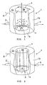
- Figure 1 shows schematically an apparatus comprising a receptacle 1.
- the receptacle 1 is constituted by a bottom 1a and an outer envelope 1b.
- a fiber mass suspension to be cleaned is fed into the receptacle 1 through an inlet channel 2 and, respectively, the cleaned fiber mass suspension is discharged from the receptacle 1 through an outlet channel 3. It is essential for the operation of the invention that the flow distance between the inlet channel 2 and the outlet channel 3 is as long as possible.
- a partition wall 4 dividing the interior of the receptacle 1 into two spaces 5a and 5b separate from each other.
- the height of the partition wall 4 is such that its lower end is situated at a distance from the bottom 1a so that the fiber mass suspension may flow below the partition wall 4 between the spaces 5a and 5b.
- the upper end of the partition wall 4 is some distance below the upper edge of the envelope 1b of the receptacle.
- the embodiment of the figure shows above the air nozzle 6 a separate mixing plate 7, which is rotated in such a way that air bubbles spread as evenly as possible all over the aeration space so that the cleaning can be made as efficient as possible.
- the air nozzles 6 may also be shaped in some other way, they can e.g. be constituted by a grate or a net, or they can be nozzles of other kinds, by means of which air bubbles of a suitable size can be distributed as well as possible in the area of the aeration space 5a.
- the fiber mass suspension is fed from the inlet channel 1 into the other outer ring-shaped space 5b.
- the air bubbles of the air to be fed into the aeration space 5a cause a reduction of the average density of the fiber mass suspension in the space including the density of the air bubbles, and then the fibre mass suspension begins to flow upwards.
- the air bubbles carry away printing ink and other impurities as well, which accumulate in the upper portion of the receptacle 1 and create a froth.
- the rest of the fiber mass flows over the upper edge of the partition wall 4 into the outer space 5b of the receptacle 1 and along that further into the lower portion of the space 5b in order to return back into the aeration space 5a below the partition wall 4.
- the froth with its impurities, accumulated in the upper portion of the receptacle 1, can be removed in several different ways, whereby they may flow over the upper edge of the receptacle 1 into a collector receptacle 8 situated outside the receptacle 1, or they can be removed by scraping mechanically or by sucking the froth from the surface by a suitable air apparatus.
- two spiral flows are created in this embodiment, both of them circulating around the edge of the partition Wall 4 between the inlet channel and the outlet channel on both sides of the receptacle 1.
- Means for removing impurities can be constituted in a simple manner, either by an overflow opening; which is arranged over the upper edge of the receptacle and which may have the breadth of the whole receptacle envelope, in principle, or the envelope 1b of the receptacle 1 can be provided with places lower than the other edges of the envelope for directing and facilitating the overflow and overfall of impurities.
- the means for removing impurities may be scrapers, suckers, fans or some other suitable devices, by which the froth and the impurities therein can be removed from the upper portion of the receptacle.
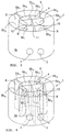
- FIGs 3 and 4 show schematically an apparatus according to the invention and a flow of a fiber mass suspension in said cleaning apparatus
- the same numerals as in Figure 1 and 2 are used for the corresponding parts. These parts are not described any further, unless it is necessary for the understanding of the invention.
- the spaces 5a and 5b are divided into several parts by using separate partition walls 9 between the partition wall 4 and the envelope 1b in the space 5b and partition walls 10 forming a cross-like structure in the aeration space 5a.
- the partition walls 9 divide the outer space 5b into sequential segments and they extend from the bottom 1a of the receptacle 1 so high that a direct flow between the segments is prevented.
- the inlet channel 2 and the outlet channel 3 of the fiber mass suspension are situated close to each other and, between them, there is a separate partition wall 11, also extending from the bottom of the receptacle 1 so high that a fiber mass suspension from the inlet channel cannot flow directly into the outlet channel.
- the partition walls 10 of the aeration space 5a are arranged in such a way that they are situated between the partition walls 9 of the outer space 5b and extend at their upper portion so high that a fiber mass suspension flow between the sectors formed in the aeration space 5a is prevented.
- the partition walls 10 in the aeration space 5a also extend preferably to the bottom of the receptacle, which intensifies the flow of the fiber mass suspension in a desired way. Simultaneously, the partition walls 10 divide the aeration space 5a into four sectors 5a 1 to 5a 4 .
- the suspension when the suspension is introduced through the inlet channel 2, it rises up along with the air bubbles of the aeration space 5a and flows back over the partition wall 4 into the segment 5a 1 on the inlet channel 2 side. Simultaneously, the froth leaves the surface of the receptacle 1 or is removed from there in a way similar to the Figures 1 and 2.
- the fiber mass suspension circulates further down, below the partition wall 4, and returns into the sector 5a 1 of the aeration space 5a, into which it had originally flown from the inlet channel 2.
- spiral turns are provided around the partition wall 4 in a manner according to the flow rate of the fiber mass suspension such that, after one or several spiral turns, the suspension flows from the sector 5a, of the aeration space 5a over the partition wall 4 into the segment 5b 2 of the outer space. From there, the suspension turns back below the partition wall 4 into the sector 5a 1, until it flows, after a sufficient number of turns, in the end portion of the segment 5b 2 into the sector 5a 2 .
- the fiber mass flow propagates spirally around the partition wall 4 from a segment into a sector and back from a sector into a segment, and moves simultaneously forward in the direction of the periphery of the partition wall 4, until it finally ends in the segment 5b 5 , which it then leaves through the outlet channel 3.
- the air bubbles cause an accumulation of impurities as a froth on the surface of the receptacle 1, from where the froth is then removed in each segment 5b 1 to 5b 5 in any manner described earlier.
- Figure 4 shows schematically how the main flow of the fiber mass propagates spirally around the partition wall 4. For the sake of clarity, Figure 4 shows by means of broken lines some partition walls remaining behind some other partition wall in the viewing direction.
- Figure 5 shows schematically another embodiment of the apparatus of the invention.
- Figure 5 uses the same numerals as the Figures 1 to 4 for the corresponding parts, and therefore, these are not described in more detail, unless it is necessary for the understanding of the invention.
- Figure 5 shows schematically a rectangular receptacle 1.
- the interior of the receptacle 1 is divided in the longitudinal direction into three parallel spaces, i.e. an aeration space 5a, and two spaces 5b in parallel with that.
- the partition walls are mounted and dimensioned such that there is a connection from the space 5a in the middle below the partition walls 4 to each space 5b on the sides and, respectively, the upper portion of the partition walls 4 is situated below the edges of the envelope 1b of the receptacle 1 such that the suspension may flow over the partition walls 4 from one space into the other.
- the aeration space 5a in the middle is divided by the partition walls 10 into the parts 5a 1 to 5a 4 and, respectively, the spaces 5b on the sides are divided by the partition walls 9 into the sequential parts 5b 1 to 5b 5 .
- the partition walls 9 extend from the bottom of the receptacle 1 right above the partition walls 4 preventing a direct suspension flow between the parts of the spaces.
- the partition walls 10 in the aeration space 5a extend above the partition walls 4 preventing a direct flow between the parts 5a 1 to 5a 4 of the aeration space 5a and also extend preferably down to the bottom of the receptacle.
- the inlet channel 2 of the suspension is connected to the first part 5a, of the aeration space 5a at the end of the receptacle, and respectively, the discharge of the fiber mass is implemented by connecting the outlet channels to the last parts 5b 5 of the spaces 5b. Further, there may be discharge chutes 8 on the sides of the receptacle 1 for collecting the froth flown over the edges of the receptacle 1 and containing impurities.
- the air is fed from the bottom of all parts 5a 1 to 5a 4 of the aeration space 5a, whereby the suspension coming from the inlet channel 2 flows upwards and is distributed into the first parts 5b 1 of the spaces 5b on both sides of the receptacle 1.
- the suspension flows downwards at the same time as the froth accumulated on the surface flows over the side walls of the receptacle 1 and the suspension, which has flown downwards, turns below the partition walls 4 back into the space 5a 1 .
- it rises upwards again and moves simultaneously forward in the longitudinal direction of the receptacle 1, whereby two spiral flows are finally created, i.e.
- the apparatus of Figure 5 could, of course, also be implemented by using only two spaces in the longitudinal direction of the receptacle 1, and respectively, the solution could also be implemented by using for instance several parallel spaces comprising, in turns, an aeration space 5a and spaces 5b on both sides thereof, respectively.
- the most preferable solution would then be a solution with an odd amount of spaces so that the outermost spaces would always be spaces 5b and the aeration space 5a would always be between them.
- the upper ends of the partition wall may thus extend above or below the upper edge of the envelope or be at the same level with it.
- the receptacle of the apparatus is divided into at least two separate spaces so that the suspension may flow from the lower portion and the upper portion of the partition wall between the spaces.
- Another essential thing is that only one of the two spaces in communication with each other is provided with an air feed required for cleaning so that the flow created by air bubbles makes the fiber mass suspension flow around the partition wall between the spaces, creating a froth containing impurities, which froth can be removed from the upper portion of the receptacle, and the fiber mass being cleaned propagates with a spiral-like movement from the inlet channel to the outlet channel and becomes cleaner all the time.
Landscapes
- Engineering & Computer Science (AREA)
- Life Sciences & Earth Sciences (AREA)
- Biotechnology (AREA)
- Wood Science & Technology (AREA)
- Mechanical Engineering (AREA)
- Paper (AREA)
- Preliminary Treatment Of Fibers (AREA)
- Treatment Of Fiber Materials (AREA)
- Cleaning In General (AREA)
- Physical Water Treatments (AREA)
- Developing Agents For Electrophotography (AREA)
- Cleaning Implements For Floors, Carpets, Furniture, Walls, And The Like (AREA)
Abstract
Description
Claims (7)
- An apparatus for cleaning a suspension preferably a fiber mass suspension, the apparatus comprising a receptacle (1), into which the suspension to be cleaned and necessary chemicals are fed, an inlet channel (2) and an outlet channel (3) for feeding the suspension into and for discharging it from the receptacle, respectively, means for feeding air into the suspension, at least one partition wall (4) for dividing the receptacle (1) into at least two separate spaces and means for removing impurities, separated along with air bubbles on the surface of the suspension, from the receptacle (1) whereby the partition wall (4) between two spaces (5a, 5b) is formed in such a way that the spaces (5a, 5b) are in communication with each other at the lower portion of the partition wall (4) and that, respectively, the suspension may flow from one space (5a, 5b) into the other at the upper portion of the partition wall (4), and that the means for feeding air into the suspension are arranged to feed air only into an aeration space (5a), which is one of said spaces being in communication with each other, whereby the suspension flows, under the influence of the air to be fed, in the aeration space (5a) upwards and, respectively, in the space (5b) on the other side of the partition wall (4) downwards so that a spiral flow around the partition wall between said two spaces (5a, 5b) is created and that the inlet channel (2) and the outlet channel (3) of the suspension are positioned such that the distance between them in the propagation direction of the suspension flow is as long as possible, characterized in that, it comprises in each space (5a, 5b) partition walls (9, 10), which divide spaces into parts (5a1 - 5a4;5b1 - 5b5), the partition walls extending from the bottom of the receptacle upwards so that they prevent the suspension from flowing directly between the parts of the same space (5a1 - 5a4; 5b1 - 5b5) the partition walls (9, 10) in one space (5b, 5a) are positioned between the partition walls (10, 9) in another space (5a, 5b) whereby the suspension from the inlet channel (2) flow into the outlet channel (3) by moving in turns from one part via a part in another space to the next part and thus around the partition wall (4) between the spaces and whereby the air fed into the aeration space causes said circulation of said suspension around the partition wall along the whole length of the partition wall (4).
- An apparatus according to claim 1, characterized in that, in the middle of the receptacle (1), there is a partition wall (4) forming a closed loop, the space within this wall forming an aeration space (5a) and the ring-shaped second space (5b) remaining outside this wall between an outer wall (1b) of the receptacle (1) and the partition wall (4), whereby the suspension flows, when the aeration space (5a) is fed with air, upwards in the aeration space (5a) and over the upper edge of the partition wall (4) into the other space (5b) and further to the lower portion of the receptacle (1) returning below the partition wall (4) back into the aeration space (5a) so that a spiral flow is created around the partition wall (4) forming the closed loop.
- An apparatus according to claim 2, characterized in that the inlet channel (2) and the outlet channel (3) are positioned on the opposite sides of the receptacle (1) in such a way that the suspension flows between the channels on both sides of the line between them, whereby air feed into the aeration space (5a) causes two spiral flows around the partition wall (4) on both sides of the line between said inlet channel (2) and outlet channel (3) from the inlet channel (2) to the outlet channel (3).
- An apparatus according to claim 2, characterized in that the partition walls (9) in the outer space (5b) extending from the bottom of the receptacle (1) upwards so that they prevent the suspension from flowing directly into the outer space (5b) between segments (5b1 to 5b5) formed between the partition walls (9), the partition walls (10) dividing the aeration space (5a) into sectors (5a1 to 5a4) are positioned such that they are situated between the partition walls (9) of the outer space (5b), that the inlet channel (2) and the outlet channel (3) of the fiber mass suspension, respectively, are positioned on the same side of the receptacle (1) close to each other, that the inlet channel (2) and the outlet channel (3) have between them a separate partition wall (11) connected at the end facing the aeration space (5a) to one partition wall (10) of the aeration space (5a) and extending from the bottom of the receptacle (1) so high that the suspension flow essentially directly from the inlet channel (2) into the outlet channel (3) is prevented, whereby the suspension from the inlet channel (2) flows from the inlet channel into the outlet channel by moving, in turns, from a segment of the outer space (5b) via a sector of the aeration space (5a) to the next segment of the outer space and thus around the receptacle (1), until it finally leaves the last segment (5b5) of the outer space through the outlet channel (3), and whereby the air fed into the sectors of the aeration space (5a) causes the circulation of said suspension around the partition wall (4) by a spiral movement so that a spiral flow is created along the whole length of the partition wall (4).
- An apparatus according to claim 1, characterized in that the inlet channel (2) and the outlet channel (3) are situated at the opposite ends of the receptacle (1), that the partition wall (4) extends from one end of the receptacle to the other so that an aeration space (5a) and another space (5b) are created between the ends between the inlet channel (2) and the outlet cannel (3) of the receptacle in such a way that, when air is fed into the aeration space, the fiber mass, when flowing through the receptacle (1), flows around the partition wall (4) in a spiral-like manner.
- An apparatus according to claim 5, characterized in that the receptacle (1) comprises at least two partition walls (4) so that an aeration space (5a) is formed between the partition walls (4), into which space the suspension is fed, and respectively, second spaces (5b) are formed between the partition walls (4) and the envelope sides of the receptacle (1) so that, when the fiber mass flows through the receptacle (1) and air is fed into the receptacle, two spiral flows circulating in directions opposite to each other are created around the partition walls (4) and that each second space (5b) is connected to the outlet channel (3).
- An apparatus according to claim 6, characterized in that the aeration space (5a) and each second space (5b), respectively, are divided by partition walls (9, 10) into sequential parts (5a1 to 5a4, 5b1 to 5b5) in the longitudinal direction in such a way that the partition walls (10) of the aeration space (5a) are situated between the partition walls (9) of each second space.
Applications Claiming Priority (3)
| Application Number | Priority Date | Filing Date | Title |
|---|---|---|---|
| FI973736 | 1997-09-19 | ||
| FI973736A FI104570B2 (en) | 1997-09-19 | 1997-09-19 | Plant for cleaning a suspension preferably fiber pulp suspension |
| PCT/FI1998/000732 WO1999015278A1 (en) | 1997-09-19 | 1998-09-17 | Apparatus for cleaning a suspension, preferably a fiber mass suspension |
Publications (2)
| Publication Number | Publication Date |
|---|---|
| EP1015123A1 EP1015123A1 (en) | 2000-07-05 |
| EP1015123B1 true EP1015123B1 (en) | 2004-06-16 |
Family
ID=8549562
Family Applications (1)
| Application Number | Title | Priority Date | Filing Date |
|---|---|---|---|
| EP98945333A Expired - Lifetime EP1015123B1 (en) | 1997-09-19 | 1998-09-17 | Apparatus for cleaning a suspension, preferably a fiber mass suspension |
Country Status (12)
| Country | Link |
|---|---|
| US (1) | US6182478B1 (en) |
| EP (1) | EP1015123B1 (en) |
| JP (1) | JP4514329B2 (en) |
| KR (1) | KR100575066B1 (en) |
| CN (1) | CN1178753C (en) |
| AT (1) | ATE269166T1 (en) |
| AU (1) | AU9268298A (en) |
| CA (1) | CA2300094C (en) |
| DE (1) | DE69824609T2 (en) |
| FI (1) | FI104570B2 (en) |
| NO (1) | NO318149B1 (en) |
| WO (1) | WO1999015278A1 (en) |
Families Citing this family (5)
| Publication number | Priority date | Publication date | Assignee | Title |
|---|---|---|---|---|
| DE19852549C2 (en) * | 1998-11-13 | 2001-08-02 | Voith Paper Patent Gmbh | Method and device for removing particles from an aqueous suspension containing paper fibers |
| EP2183428A4 (en) * | 2007-07-24 | 2012-05-30 | Herbert Gunther Joachim Langner | Method and apparatus for separating waste products from cellulose fibres in a paper recycling process |
| JP2010043374A (en) * | 2008-08-12 | 2010-02-25 | Voith Patent Gmbh | Device for cleaning flotator air nozzle, and flotator |
| CN104928959B (en) * | 2015-03-23 | 2017-01-25 | 济南大学 | A rotorless air vortex pulping equipment |
| CN112316881A (en) * | 2020-12-28 | 2021-02-05 | 浙江帕瓦新能源股份有限公司 | Multistage reaction kettle |
Family Cites Families (4)
| Publication number | Priority date | Publication date | Assignee | Title |
|---|---|---|---|---|
| SE388133B (en) | 1974-11-25 | 1976-09-27 | Euroc Administration Ab | KIT AND DEVICE FOR MICROFLOTATION WITH PRESSURE SWEET |
| AU601698B2 (en) * | 1985-11-27 | 1990-09-20 | Standard Oil Company, The | Apparatus and method for froth flotation |
| DE3883530T2 (en) | 1988-06-27 | 1994-02-17 | Anomyme Acec Transport Charler | Fast switch operated by a trip circuit. |
| US5509535A (en) * | 1994-07-12 | 1996-04-23 | Hydrochem Developments Ltd. | Flotation apparatus |
-
1997
- 1997-09-19 FI FI973736A patent/FI104570B2/en not_active IP Right Cessation
-
1998
- 1998-09-17 JP JP2000512638A patent/JP4514329B2/en not_active Expired - Fee Related
- 1998-09-17 DE DE1998624609 patent/DE69824609T2/en not_active Expired - Lifetime
- 1998-09-17 CN CNB988092255A patent/CN1178753C/en not_active Expired - Fee Related
- 1998-09-17 AT AT98945333T patent/ATE269166T1/en active
- 1998-09-17 KR KR1020007002878A patent/KR100575066B1/en not_active Expired - Fee Related
- 1998-09-17 AU AU92682/98A patent/AU9268298A/en not_active Abandoned
- 1998-09-17 EP EP98945333A patent/EP1015123B1/en not_active Expired - Lifetime
- 1998-09-17 CA CA 2300094 patent/CA2300094C/en not_active Expired - Fee Related
- 1998-09-17 WO PCT/FI1998/000732 patent/WO1999015278A1/en not_active Ceased
-
2000
- 2000-02-10 NO NO20000670A patent/NO318149B1/en not_active IP Right Cessation
- 2000-03-13 US US09/524,344 patent/US6182478B1/en not_active Expired - Fee Related
Also Published As
| Publication number | Publication date |
|---|---|
| JP4514329B2 (en) | 2010-07-28 |
| KR100575066B1 (en) | 2006-05-15 |
| DE69824609D1 (en) | 2004-07-22 |
| CA2300094A1 (en) | 1999-04-01 |
| EP1015123A1 (en) | 2000-07-05 |
| ATE269166T1 (en) | 2004-07-15 |
| US6182478B1 (en) | 2001-02-06 |
| KR20010024122A (en) | 2001-03-26 |
| NO20000670D0 (en) | 2000-02-10 |
| AU9268298A (en) | 1999-04-12 |
| JP2001517550A (en) | 2001-10-09 |
| FI104570B2 (en) | 2004-05-24 |
| CA2300094C (en) | 2008-11-18 |
| CN1270545A (en) | 2000-10-18 |
| NO20000670L (en) | 2000-03-14 |
| FI973736L (en) | 1999-03-20 |
| FI973736A0 (en) | 1997-09-19 |
| NO318149B1 (en) | 2005-02-07 |
| DE69824609T2 (en) | 2005-06-23 |
| WO1999015278A1 (en) | 1999-04-01 |
| CN1178753C (en) | 2004-12-08 |
Similar Documents
| Publication | Publication Date | Title |
|---|---|---|
| US3471026A (en) | Continuous rotary disc filters | |
| US3754656A (en) | Floatation separators | |
| EP0122747A2 (en) | Apparatus for deinking | |
| GB2055597A (en) | Vibratory screening apparatus for screening liquids | |
| US5650044A (en) | Paper-pulp deinking method and equipment to implement this method | |
| US6920983B2 (en) | Device for separating solids from liquids by means of flotation | |
| US6182478B1 (en) | Apparatus for cleaning a suspension, preferably a fiber mass suspension | |
| JPH06170117A (en) | Underlying water collecting module and system for filtering device | |
| US3765532A (en) | Wood chip washer | |
| US3865719A (en) | Flotation device for a fibrous suspension | |
| CA1176576A (en) | Filter apparatus | |
| CN116944031A (en) | Special equipment for tungsten powder impurity treatment | |
| NL192327C (en) | Filter drum for filtering water from a granulated blast furnace slag water mixture. | |
| US5705068A (en) | Feeding suspension to a disc filter | |
| GB1602673A (en) | Apparatus for separating from each other the components of a mixture of water oil and dirt (sludge) | |
| JPS5818495A (en) | Used paper regenerating apparatus | |
| AU678020B2 (en) | A clarifier for the separation of solids in waste water | |
| EP0414602B1 (en) | Method and apparatus for removing impurities from paper pulp in pulpers | |
| US4440109A (en) | Method and apparatus for rearing post-larvae shrimp | |
| JPH06316886A (en) | Pressure-type flotation machine | |
| GB2118452A (en) | Filtration method and apparatus | |
| CN211330256U (en) | Large granule impurity screening plant | |
| EP0004934B1 (en) | A plant for biological purification of waste water | |
| EP0475669B1 (en) | A mass tower and apparatus for the discharge thereof | |
| GB2131330A (en) | Electrostatic dust separator |
Legal Events
| Date | Code | Title | Description |
|---|---|---|---|
| PUAI | Public reference made under article 153(3) epc to a published international application that has entered the european phase |
Free format text: ORIGINAL CODE: 0009012 |
|
| 17P | Request for examination filed |
Effective date: 20000303 |
|
| AK | Designated contracting states |
Kind code of ref document: A1 Designated state(s): AT DE FR GB IT SE |
|
| RAP1 | Party data changed (applicant data changed or rights of an application transferred) |
Owner name: METSO PAPER, INC. |
|
| GRAP | Despatch of communication of intention to grant a patent |
Free format text: ORIGINAL CODE: EPIDOSNIGR1 |
|
| GRAS | Grant fee paid |
Free format text: ORIGINAL CODE: EPIDOSNIGR3 |
|
| GRAA | (expected) grant |
Free format text: ORIGINAL CODE: 0009210 |
|
| AK | Designated contracting states |
Kind code of ref document: B1 Designated state(s): AT DE FR GB IT SE |
|
| REG | Reference to a national code |
Ref country code: GB Ref legal event code: FG4D |
|
| REF | Corresponds to: |
Ref document number: 69824609 Country of ref document: DE Date of ref document: 20040722 Kind code of ref document: P |
|
| REG | Reference to a national code |
Ref country code: SE Ref legal event code: TRGR |
|
| ET | Fr: translation filed | ||
| PLBE | No opposition filed within time limit |
Free format text: ORIGINAL CODE: 0009261 |
|
| STAA | Information on the status of an ep patent application or granted ep patent |
Free format text: STATUS: NO OPPOSITION FILED WITHIN TIME LIMIT |
|
| 26N | No opposition filed |
Effective date: 20050317 |
|
| PGFP | Annual fee paid to national office [announced via postgrant information from national office to epo] |
Ref country code: SE Payment date: 20100914 Year of fee payment: 13 Ref country code: FR Payment date: 20101005 Year of fee payment: 13 Ref country code: AT Payment date: 20100914 Year of fee payment: 13 |
|
| PGFP | Annual fee paid to national office [announced via postgrant information from national office to epo] |
Ref country code: GB Payment date: 20100921 Year of fee payment: 13 |
|
| PGFP | Annual fee paid to national office [announced via postgrant information from national office to epo] |
Ref country code: DE Payment date: 20100922 Year of fee payment: 13 |
|
| PGFP | Annual fee paid to national office [announced via postgrant information from national office to epo] |
Ref country code: IT Payment date: 20100927 Year of fee payment: 13 |
|
| GBPC | Gb: european patent ceased through non-payment of renewal fee |
Effective date: 20110917 |
|
| PG25 | Lapsed in a contracting state [announced via postgrant information from national office to epo] |
Ref country code: IT Free format text: LAPSE BECAUSE OF NON-PAYMENT OF DUE FEES Effective date: 20110917 |
|
| REG | Reference to a national code |
Ref country code: FR Ref legal event code: ST Effective date: 20120531 |
|
| REG | Reference to a national code |
Ref country code: SE Ref legal event code: EUG |
|
| REG | Reference to a national code |
Ref country code: DE Ref legal event code: R119 Ref document number: 69824609 Country of ref document: DE Effective date: 20120403 |
|
| PG25 | Lapsed in a contracting state [announced via postgrant information from national office to epo] |
Ref country code: DE Free format text: LAPSE BECAUSE OF NON-PAYMENT OF DUE FEES Effective date: 20120403 |
|
| PG25 | Lapsed in a contracting state [announced via postgrant information from national office to epo] |
Ref country code: GB Free format text: LAPSE BECAUSE OF NON-PAYMENT OF DUE FEES Effective date: 20110917 Ref country code: FR Free format text: LAPSE BECAUSE OF NON-PAYMENT OF DUE FEES Effective date: 20110930 |
|
| REG | Reference to a national code |
Ref country code: AT Ref legal event code: MM01 Ref document number: 269166 Country of ref document: AT Kind code of ref document: T Effective date: 20110917 |
|
| PG25 | Lapsed in a contracting state [announced via postgrant information from national office to epo] |
Ref country code: AT Free format text: LAPSE BECAUSE OF NON-PAYMENT OF DUE FEES Effective date: 20110917 |
|
| PG25 | Lapsed in a contracting state [announced via postgrant information from national office to epo] |
Ref country code: SE Free format text: LAPSE BECAUSE OF NON-PAYMENT OF DUE FEES Effective date: 20110918 |