EP1015115B1 - Parallel reaction station with magnetic stirring - Google Patents
Parallel reaction station with magnetic stirring Download PDFInfo
- Publication number
- EP1015115B1 EP1015115B1 EP98955399A EP98955399A EP1015115B1 EP 1015115 B1 EP1015115 B1 EP 1015115B1 EP 98955399 A EP98955399 A EP 98955399A EP 98955399 A EP98955399 A EP 98955399A EP 1015115 B1 EP1015115 B1 EP 1015115B1
- Authority
- EP
- European Patent Office
- Prior art keywords
- adapter block
- stirrer
- magnetic
- reaction vessel
- recess
- Prior art date
- Legal status (The legal status is an assumption and is not a legal conclusion. Google has not performed a legal analysis and makes no representation as to the accuracy of the status listed.)
- Expired - Lifetime
Links
Images


Classifications
-
- B—PERFORMING OPERATIONS; TRANSPORTING
- B01—PHYSICAL OR CHEMICAL PROCESSES OR APPARATUS IN GENERAL
- B01L—CHEMICAL OR PHYSICAL LABORATORY APPARATUS FOR GENERAL USE
- B01L3/00—Containers or dishes for laboratory use, e.g. laboratory glassware; Droppers
- B01L3/06—Crystallising dishes
-
- B—PERFORMING OPERATIONS; TRANSPORTING
- B01—PHYSICAL OR CHEMICAL PROCESSES OR APPARATUS IN GENERAL
- B01F—MIXING, e.g. DISSOLVING, EMULSIFYING OR DISPERSING
- B01F33/00—Other mixers; Mixing plants; Combinations of mixers
- B01F33/45—Magnetic mixers; Mixers with magnetically driven stirrers
- B01F33/452—Magnetic mixers; Mixers with magnetically driven stirrers using independent floating stirring elements
-
- B—PERFORMING OPERATIONS; TRANSPORTING
- B01—PHYSICAL OR CHEMICAL PROCESSES OR APPARATUS IN GENERAL
- B01J—CHEMICAL OR PHYSICAL PROCESSES, e.g. CATALYSIS OR COLLOID CHEMISTRY; THEIR RELEVANT APPARATUS
- B01J19/00—Chemical, physical or physico-chemical processes in general; Their relevant apparatus
- B01J19/0046—Sequential or parallel reactions, e.g. for the synthesis of polypeptides or polynucleotides; Apparatus and devices for combinatorial chemistry or for making molecular arrays
-
- B—PERFORMING OPERATIONS; TRANSPORTING
- B01—PHYSICAL OR CHEMICAL PROCESSES OR APPARATUS IN GENERAL
- B01J—CHEMICAL OR PHYSICAL PROCESSES, e.g. CATALYSIS OR COLLOID CHEMISTRY; THEIR RELEVANT APPARATUS
- B01J2219/00—Chemical, physical or physico-chemical processes in general; Their relevant apparatus
- B01J2219/00274—Sequential or parallel reactions; Apparatus and devices for combinatorial chemistry or for making arrays; Chemical library technology
- B01J2219/00277—Apparatus
- B01J2219/00279—Features relating to reactor vessels
- B01J2219/00281—Individual reactor vessels
- B01J2219/00283—Reactor vessels with top opening
-
- B—PERFORMING OPERATIONS; TRANSPORTING
- B01—PHYSICAL OR CHEMICAL PROCESSES OR APPARATUS IN GENERAL
- B01J—CHEMICAL OR PHYSICAL PROCESSES, e.g. CATALYSIS OR COLLOID CHEMISTRY; THEIR RELEVANT APPARATUS
- B01J2219/00—Chemical, physical or physico-chemical processes in general; Their relevant apparatus
- B01J2219/00274—Sequential or parallel reactions; Apparatus and devices for combinatorial chemistry or for making arrays; Chemical library technology
- B01J2219/00277—Apparatus
- B01J2219/00279—Features relating to reactor vessels
- B01J2219/00306—Reactor vessels in a multiple arrangement
- B01J2219/00308—Reactor vessels in a multiple arrangement interchangeably mounted in racks or blocks
-
- B—PERFORMING OPERATIONS; TRANSPORTING
- B01—PHYSICAL OR CHEMICAL PROCESSES OR APPARATUS IN GENERAL
- B01J—CHEMICAL OR PHYSICAL PROCESSES, e.g. CATALYSIS OR COLLOID CHEMISTRY; THEIR RELEVANT APPARATUS
- B01J2219/00—Chemical, physical or physico-chemical processes in general; Their relevant apparatus
- B01J2219/00274—Sequential or parallel reactions; Apparatus and devices for combinatorial chemistry or for making arrays; Chemical library technology
- B01J2219/00277—Apparatus
- B01J2219/00279—Features relating to reactor vessels
- B01J2219/00331—Details of the reactor vessels
- B01J2219/00333—Closures attached to the reactor vessels
- B01J2219/00344—Caps
- B01J2219/00346—Screw-caps
-
- B—PERFORMING OPERATIONS; TRANSPORTING
- B01—PHYSICAL OR CHEMICAL PROCESSES OR APPARATUS IN GENERAL
- B01J—CHEMICAL OR PHYSICAL PROCESSES, e.g. CATALYSIS OR COLLOID CHEMISTRY; THEIR RELEVANT APPARATUS
- B01J2219/00—Chemical, physical or physico-chemical processes in general; Their relevant apparatus
- B01J2219/00274—Sequential or parallel reactions; Apparatus and devices for combinatorial chemistry or for making arrays; Chemical library technology
- B01J2219/00277—Apparatus
- B01J2219/00351—Means for dispensing and evacuation of reagents
-
- B—PERFORMING OPERATIONS; TRANSPORTING
- B01—PHYSICAL OR CHEMICAL PROCESSES OR APPARATUS IN GENERAL
- B01J—CHEMICAL OR PHYSICAL PROCESSES, e.g. CATALYSIS OR COLLOID CHEMISTRY; THEIR RELEVANT APPARATUS
- B01J2219/00—Chemical, physical or physico-chemical processes in general; Their relevant apparatus
- B01J2219/00274—Sequential or parallel reactions; Apparatus and devices for combinatorial chemistry or for making arrays; Chemical library technology
- B01J2219/00277—Apparatus
- B01J2219/00351—Means for dispensing and evacuation of reagents
- B01J2219/00389—Feeding through valves
- B01J2219/00391—Rotary valves
-
- B—PERFORMING OPERATIONS; TRANSPORTING
- B01—PHYSICAL OR CHEMICAL PROCESSES OR APPARATUS IN GENERAL
- B01J—CHEMICAL OR PHYSICAL PROCESSES, e.g. CATALYSIS OR COLLOID CHEMISTRY; THEIR RELEVANT APPARATUS
- B01J2219/00—Chemical, physical or physico-chemical processes in general; Their relevant apparatus
- B01J2219/00274—Sequential or parallel reactions; Apparatus and devices for combinatorial chemistry or for making arrays; Chemical library technology
- B01J2219/00277—Apparatus
- B01J2219/00479—Means for mixing reactants or products in the reaction vessels
- B01J2219/00481—Means for mixing reactants or products in the reaction vessels by the use of moving stirrers within the reaction vessels
-
- B—PERFORMING OPERATIONS; TRANSPORTING
- B01—PHYSICAL OR CHEMICAL PROCESSES OR APPARATUS IN GENERAL
- B01J—CHEMICAL OR PHYSICAL PROCESSES, e.g. CATALYSIS OR COLLOID CHEMISTRY; THEIR RELEVANT APPARATUS
- B01J2219/00—Chemical, physical or physico-chemical processes in general; Their relevant apparatus
- B01J2219/00274—Sequential or parallel reactions; Apparatus and devices for combinatorial chemistry or for making arrays; Chemical library technology
- B01J2219/00277—Apparatus
- B01J2219/00495—Means for heating or cooling the reaction vessels
-
- B—PERFORMING OPERATIONS; TRANSPORTING
- B01—PHYSICAL OR CHEMICAL PROCESSES OR APPARATUS IN GENERAL
- B01J—CHEMICAL OR PHYSICAL PROCESSES, e.g. CATALYSIS OR COLLOID CHEMISTRY; THEIR RELEVANT APPARATUS
- B01J2219/00—Chemical, physical or physico-chemical processes in general; Their relevant apparatus
- B01J2219/00274—Sequential or parallel reactions; Apparatus and devices for combinatorial chemistry or for making arrays; Chemical library technology
- B01J2219/00583—Features relative to the processes being carried out
- B01J2219/00585—Parallel processes
-
- C—CHEMISTRY; METALLURGY
- C40—COMBINATORIAL TECHNOLOGY
- C40B—COMBINATORIAL CHEMISTRY; LIBRARIES, e.g. CHEMICAL LIBRARIES
- C40B60/00—Apparatus specially adapted for use in combinatorial chemistry or with libraries
- C40B60/14—Apparatus specially adapted for use in combinatorial chemistry or with libraries for creating libraries
-
- G—PHYSICS
- G01—MEASURING; TESTING
- G01N—INVESTIGATING OR ANALYSING MATERIALS BY DETERMINING THEIR CHEMICAL OR PHYSICAL PROPERTIES
- G01N35/00—Automatic analysis not limited to methods or materials provided for in any single one of groups G01N1/00 - G01N33/00; Handling materials therefor
- G01N2035/00346—Heating or cooling arrangements
- G01N2035/00356—Holding samples at elevated temperature (incubation)
- G01N2035/00366—Several different temperatures used
-
- G—PHYSICS
- G01—MEASURING; TESTING
- G01N—INVESTIGATING OR ANALYSING MATERIALS BY DETERMINING THEIR CHEMICAL OR PHYSICAL PROPERTIES
- G01N35/00—Automatic analysis not limited to methods or materials provided for in any single one of groups G01N1/00 - G01N33/00; Handling materials therefor
- G01N2035/00346—Heating or cooling arrangements
- G01N2035/00356—Holding samples at elevated temperature (incubation)
- G01N2035/00376—Conductive heating, e.g. heated plates
-
- G—PHYSICS
- G01—MEASURING; TESTING
- G01N—INVESTIGATING OR ANALYSING MATERIALS BY DETERMINING THEIR CHEMICAL OR PHYSICAL PROPERTIES
- G01N35/00—Automatic analysis not limited to methods or materials provided for in any single one of groups G01N1/00 - G01N33/00; Handling materials therefor
- G01N2035/00346—Heating or cooling arrangements
- G01N2035/00356—Holding samples at elevated temperature (incubation)
- G01N2035/00386—Holding samples at elevated temperature (incubation) using fluid heat transfer medium
- G01N2035/00396—Holding samples at elevated temperature (incubation) using fluid heat transfer medium where the fluid is a liquid
-
- G—PHYSICS
- G01—MEASURING; TESTING
- G01N—INVESTIGATING OR ANALYSING MATERIALS BY DETERMINING THEIR CHEMICAL OR PHYSICAL PROPERTIES
- G01N35/00—Automatic analysis not limited to methods or materials provided for in any single one of groups G01N1/00 - G01N33/00; Handling materials therefor
- G01N2035/00465—Separating and mixing arrangements
- G01N2035/00534—Mixing by a special element, e.g. stirrer
-
- G—PHYSICS
- G01—MEASURING; TESTING
- G01N—INVESTIGATING OR ANALYSING MATERIALS BY DETERMINING THEIR CHEMICAL OR PHYSICAL PROPERTIES
- G01N35/00—Automatic analysis not limited to methods or materials provided for in any single one of groups G01N1/00 - G01N33/00; Handling materials therefor
- G01N35/02—Automatic analysis not limited to methods or materials provided for in any single one of groups G01N1/00 - G01N33/00; Handling materials therefor using a plurality of sample containers moved by a conveyor system past one or more treatment or analysis stations
- G01N35/025—Automatic analysis not limited to methods or materials provided for in any single one of groups G01N1/00 - G01N33/00; Handling materials therefor using a plurality of sample containers moved by a conveyor system past one or more treatment or analysis stations having a carousel or turntable for reaction cells or cuvettes
Definitions
- the present invention relates to a device capable of accommodating a plurality of reaction vessels being specifically adapted so that when placed in a magnetic field, such as that generated by a laboratory magnetic stirrer, any reaction vessel accommodated by the device is in an effective position for stirring with respect to the magnetic field.
- US 4 477 192 discloses a four-cell stirrer in which the reaction vessel cells are located in a fixed cooling block directly above a magnetic rotor
- the present device is advantageous over known devices in that it allows a conventional magnetic stirrer to be used for parallel synthesis and hence provides significant economic advantages compared with previously known parallel reaction stations.
- a means has now been found which permits the use of existing laboratory magnetic stirrers in parallel syntheses by providing a device which is capable of securely accommodating a plurality of reaction vessels said device being specifically adapted so that when correctly located within a magnetic field generated by a laboratory magnetic stirrer each and every reaction vessel is effectively positioned for stirring with respect to the magnetic field.
- any reaction vessel, placed in the device and equipped with a magnetic stir bar, is subject to smooth and efficient agitation.
- the present invention provides a device comprising an adapter block for seating on a laboratory magnetic stirrer and having a recess on one face having a rim for receiving and locating the stirrer plate of a said stirrer, the adapter block containing holders for holding a plurality of reaction vessels in positions whose centres are distributed around the recess outside its periphery, so that, when the adapter block is co-operatively positioned on a laboratory magnetic stirrer within a magnetic field generated by said stirrer such reaction vessel positions are effectively located for stirring by the magnetic field.
- the holders will comprise a plurality of sockets each designed to securely accommodate a reaction vessel.
- the adapter block incorporates said recess which engages with the laboratory magnetic stirrer thereby ensuring the adapter block is correctly located within the magnetic field of the laboratory magnetic stirrer such that each and every position for holding a reaction vessel is effectively located for stirring with respect to the magnetic field.
- the recess of the adapter block will be arranged to ensure the adapter block is effectively positioned such that each and every position for holding a reaction vessel is effectively located for equivalent stirring with respect to the magnetic field.
- the adapter block may be cast in any suitable form, however in a particularly preferred arrangement the adapter block is circular in shape.
- the adapter block may be used in co-operation with any laboratory magnetic stirrer with a suitable circular magnetic/hotplate.
- Preferred laboratory stirrers include the IKA RCT basic hotplate stirrers, the IKAMAG REO, the Heidolph MR3001, the Heidolph MR3002, and the Heidolph MR3000.
- the sockets are arranged about the perimeter of the adapter block.
- the adapter block is made of chemically resistant material for example PTFE or a metal such as aluminium or stainless steel.
- the adapter block may optionally be constructed from heat conducting material for example aluminium or stainless steel.
- the device may incorporate a condenser unit such that the contents of the reaction vessels may be heated to reflux.
- the adapter block or condenser unit will incorporate a gas manifold.
- gas flow or vacuum supply to each of the reaction vessels may be individually controlled.
- the gas manifold may be located anywhere on the device, however in a particularly preferred arrangement the gas manifold is located at the centre of the parallel reaction station.
- the adapter block is capable of being constructed to accommodate any size laboratory reaction vessel however 16 and 24 mm o.d. test tubes are particularly preferred.
- the condenser unit when provided, will be assembled such that the unit is in direct contact with the reaction vessels as they project from the adapter block.
- the condenser unit will be constructed from a material of high specific heat capacity for example stainless steel.
- the condenser unit is liquid cooled.
- the device illustrated in Figure 1 comprises the adapter block (1) which is constructed from PTFE and is circular in shape with sockets (2) suitable for securely accommodating the test tube reaction vessels (3) located about the perimeter of the device.
- One face of the device is equipped with a central recess whereby the stirrer plate of the magnetic stirrer (5) is secured within the recess thereby ensuring that the device is effectively located for stirring within the magnetic field.
- a gas manifold comprising a gas inlet (4) and gas outlets (4a) is located at the centre of the adapter block.
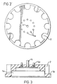
- Figures 2 and 3 show the location of the gas inlet (4) and gas outlets (4a) more clearly.
- Figure 3 illustrates the central recess (5a) formed by the raised rim (5b) which ensure the adapter block is correctly located within the magnetic field of the laboratory stirrer.
- the reaction vessel position defined by the holding socket (2) lies wholly outside the recess (5a) when viewed in plan, which enables a base portion of a reaction vessel held by the socket (2) at the level of the recess.
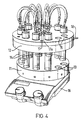
- the device shown in Figure 4 comprises an adapter block (11) and a condenser unit (12) both of which are constructed from aluminium and are circular in shape.
- the adapter block comprises sockets (13) located about the perimeter of the device suitable for accommodating the test tube reaction vessels (14).
- the condenser unit contains openings (15) through which the test tube reaction vessels pass.
- the condenser unit is equipped with inlet/outlets (18) which permit cooling fluid to flow through the condenser unit.
- the adapter block and condenser unit are substantially parallel to one another.
- One face of the adapter block is equipped with a recess whereby the hotplate of a hotplate/magnetic stirrer (16) may be secured within the recess thereby ensuring that the adapter block is effectively located within the magnetic field.
- a gas manifold comprising a gas inlet (17) and gas outlets (17a) is located at the centre of the condenser unit.
- FIGS 5 and 6 illustrate more clearly the cooling fluid inlet/outlets (18) the openings through which the reaction vessels pass (15) and the gas inlet (17) and the gas outlets (17a).
- the device comprises an adapter block as described hereinbefore wherein the device is permanently fixed to a laboratory magnetic or hotplate magnetic stirrer.
Landscapes
- Chemical & Material Sciences (AREA)
- Chemical Kinetics & Catalysis (AREA)
- Organic Chemistry (AREA)
- Crystallography & Structural Chemistry (AREA)
- Health & Medical Sciences (AREA)
- Clinical Laboratory Science (AREA)
- Mixers With Rotating Receptacles And Mixers With Vibration Mechanisms (AREA)
- Automatic Analysis And Handling Materials Therefor (AREA)
- Steering Control In Accordance With Driving Conditions (AREA)
- Devices For Use In Laboratory Experiments (AREA)
- Physical Or Chemical Processes And Apparatus (AREA)
- Organic Low-Molecular-Weight Compounds And Preparation Thereof (AREA)
- Valve Device For Special Equipments (AREA)
- Accessories For Mixers (AREA)
Abstract
Description
Claims (12)
- A device comprising an adapter block [1] for seating on a laboratory magnetic stirrer [5, 16] and having a recess [5a] on one face having a rim [5b] for receiving and locating the stirrer plate of a said stirrer [5, 16], the adapter block [1] containing holders [2, 13] for holding a plurality of reaction vessels [3, 14] in positions whose centres are distributed around the recess [5a] outside its periphery, so that, when the adapter block [1] is co-operatively positioned on a laboratory magnetic stirrer [5, 16] within a magnetic field generated by said stirrer, such reaction vessel positions [2, 13] are effectively located for stirring by the magnetic field.
- A device according to claim 1 wherein the adapter block [1] is arranged to ensure that each and every position [2, 13] for holding a reaction vessel is effectively located for equivalent stirring.
- A device according to claim 1 or 2 wherein the holders [2, 13] comprise a plurality of sockets each designed to securely accommodate a reaction vessel [3, 14].
- A device according to claim 3 wherein the sockets are arranged about the perimeter of the adapter block [1].
- A device according to any of claim 1 to 4 wherein the device incorporates a condenser unit [12].
- A device according to claim 5 wherein the adapter block [1] is made of heat conducting material.
- A device according to any preceding claim wherein the adapter block [1] is circular in shape.
- A device according to any preceding claim wherein the adapter block [1] is made of chemically resistant material.
- A device according to any preceding claim wherein the adapter block [1] incorporates a gas manifold [4, 4a].
- A device according to any preceding claim, wherein a base portion of each said vessel can be held substantially at the level of the recess [5a].
- A magnetic or hotplate magnetic stirrer fitted with a device according to any preceding claim.
- A magnetic or hotplate magnetic stirrer according to claim 11 wherein the device incorporates a condenser unit.
Applications Claiming Priority (3)
| Application Number | Priority Date | Filing Date | Title |
|---|---|---|---|
| GB9719774 | 1997-09-18 | ||
| GBGB9719774.3A GB9719774D0 (en) | 1997-09-18 | 1997-09-18 | Device |
| PCT/EP1998/005901 WO1999013988A1 (en) | 1997-09-18 | 1998-09-17 | Parallel reaction station with magnetic stirring |
Publications (2)
| Publication Number | Publication Date |
|---|---|
| EP1015115A1 EP1015115A1 (en) | 2000-07-05 |
| EP1015115B1 true EP1015115B1 (en) | 2003-07-09 |
Family
ID=10819215
Family Applications (1)
| Application Number | Title | Priority Date | Filing Date |
|---|---|---|---|
| EP98955399A Expired - Lifetime EP1015115B1 (en) | 1997-09-18 | 1998-09-17 | Parallel reaction station with magnetic stirring |
Country Status (9)
| Country | Link |
|---|---|
| US (1) | US6905656B1 (en) |
| EP (1) | EP1015115B1 (en) |
| JP (1) | JP2001516641A (en) |
| AT (1) | ATE244605T1 (en) |
| AU (1) | AU1225599A (en) |
| DE (1) | DE69816311T2 (en) |
| ES (1) | ES2202906T3 (en) |
| GB (2) | GB9719774D0 (en) |
| WO (1) | WO1999013988A1 (en) |
Cited By (2)
| Publication number | Priority date | Publication date | Assignee | Title |
|---|---|---|---|---|
| US7704458B2 (en) | 2005-03-02 | 2010-04-27 | Asynt Limited | Reaction plate adaptor apparatus |
| CN111318240A (en) * | 2018-12-13 | 2020-06-23 | 郑州凯鹏实验仪器有限公司 | Novel parallel reaction instrument |
Families Citing this family (36)
| Publication number | Priority date | Publication date | Assignee | Title |
|---|---|---|---|---|
| DE10225930A1 (en) * | 2002-06-11 | 2003-12-24 | Basf Ag | Reactor system for carrying out chemical reactions in parallel, in particular polymerization reactions |
| FR2806323B1 (en) * | 2000-03-17 | 2002-10-11 | Centre Nat Rech Scient | MODULE AND APPARATUS FOR SYNTHESIS OF ORGANIC OR OTHER MOLECULES |
| GB2364258A (en) * | 2000-07-01 | 2002-01-23 | Stuart John Simcock | Reaction station with reactor vessel support |
| DE10225931A1 (en) * | 2002-06-11 | 2003-12-24 | Basf Ag | Reactor system for carrying out chemical reactions in parallel, in particular polymerization reactions |
| WO2004073865A2 (en) * | 2003-02-18 | 2004-09-02 | Argonaut Technologies, Inc. | Radial continuous coupled magnetic mixing device |
| DE10322331B4 (en) * | 2003-05-17 | 2005-07-14 | Heidolph Instruments Gmbh & Co.Kg | Device for carrying out a parallel synthesis of compounds |
| GB2402090B (en) | 2003-05-30 | 2006-12-06 | Electrothermal Eng Ltd | Multi-station reaction apparatus |
| US7494267B2 (en) * | 2005-08-30 | 2009-02-24 | Chemglass, Inc. | Reaction block for supporting flasks of different sizes for chemical synthesis on a hot plate stirrer |
| USD558888S1 (en) | 2005-08-30 | 2008-01-01 | Chemglass, Inc. | Reaction block for chemical synthesis for use upon a hot plate stirrer |
| US20080059909A1 (en) * | 2006-09-01 | 2008-03-06 | Rita Parada | Enhanced list based user interface in mobile context |
| US20080151683A1 (en) * | 2006-11-14 | 2008-06-26 | Charles Meadows | Stir-bag system with stand and turbulence member |
| US20080151686A1 (en) * | 2006-11-14 | 2008-06-26 | Charles Meadows | Mixing bag for use with nonabrasive stir bar |
| US7963733B2 (en) * | 2008-10-01 | 2011-06-21 | Perfect Systems, Llc | Apparatus for and a method of binding of a perfect bound book |
| US8398297B2 (en) * | 2009-08-13 | 2013-03-19 | General Electric Company | Electromagnetic stirring apparatus |
| JP5487432B2 (en) * | 2009-08-28 | 2014-05-07 | 東京理化器械株式会社 | Thermostatic device |
| GB2591198B (en) | 2014-04-04 | 2021-10-27 | It Is Int Ltd | Biochemical reaction system |
| CN105032328A (en) * | 2015-08-24 | 2015-11-11 | 郑州大学 | Chemical parallel reaction device |
| US10701765B2 (en) | 2015-08-26 | 2020-06-30 | Bernard Robert McKellar | Flexible convertible hotplate adapter for rounded vessels and objects |
| TWI590817B (en) * | 2015-10-14 | 2017-07-11 | 鈺邦科技股份有限公司 | Impregnation equipment and impregnation method |
| CN105543089A (en) * | 2016-03-08 | 2016-05-04 | 湖南圣湘生物科技有限公司 | Magnetic bead based nucleic acid extraction device and method |
| CN107456942A (en) * | 2016-06-02 | 2017-12-12 | 建湖县联华玻璃仪器厂 | A kind of parallel reaction instrument |
| CN106237906A (en) * | 2016-08-18 | 2016-12-21 | 娄土岭 | Thermal insulation coatings bucket is used in a kind of casting |
| JP6901084B2 (en) * | 2017-05-12 | 2021-07-14 | マックエンジニアリング株式会社 | Desktop continuous stirring tank type reactor |
| DE202017106756U1 (en) * | 2017-11-08 | 2019-02-11 | Mikrowellen Labor Technik Ag | Stirring device and stirring system |
| CN113015910A (en) * | 2019-04-22 | 2021-06-22 | 深圳迈瑞生物医疗电子股份有限公司 | Mixing device and mixing method of magnetic bead reagent and sample analysis equipment |
| USD1013203S1 (en) | 2019-10-25 | 2024-01-30 | Hans Heidolph GmbH | Magnetic stirrer |
| USD930721S1 (en) * | 2020-11-23 | 2021-09-14 | Elliot Kremerman | Circular spinner |
| USD930722S1 (en) * | 2020-11-23 | 2021-09-14 | Elliot Kremerman | Spinner with magnets |
| JP7076838B2 (en) * | 2020-12-11 | 2022-05-30 | マックエンジニアリング株式会社 | Desktop continuous stirring tank type reactor |
| USD934316S1 (en) | 2021-08-02 | 2021-10-26 | Elliot Kremerman | Spinner |
| USD934930S1 (en) | 2021-08-02 | 2021-11-02 | Elliot Kremerman | Spinner |
| USD935497S1 (en) | 2021-08-02 | 2021-11-09 | Elliot Kremerman | Spinner |
| USD935496S1 (en) | 2021-08-02 | 2021-11-09 | Elliot Kremerman | Spinner |
| KR20230089605A (en) | 2021-12-13 | 2023-06-21 | 삼성전자주식회사 | Heat exchanger and heat exchanging system comprising the same |
| CN114307929B (en) * | 2022-01-11 | 2024-01-16 | 烟台松川自动化科技有限公司 | A multi-position independent automated parallel reaction device |
| USD1104292S1 (en) * | 2022-08-05 | 2025-12-02 | Ohaus instruments (Changzhou) Co. Ltd. | Shaker |
Family Cites Families (23)
| Publication number | Priority date | Publication date | Assignee | Title |
|---|---|---|---|---|
| US359129A (en) * | 1887-03-08 | Scrubbing-brush | ||
| US3356346A (en) * | 1966-01-03 | 1967-12-05 | Landsberger Kurt | Test tube stirring support |
| SE397637B (en) * | 1976-03-09 | 1977-11-14 | Wik G | MAGNETOMRORARE |
| JPS55136956A (en) * | 1979-04-12 | 1980-10-25 | Olympus Optical Co Ltd | Automatic analyzer |
| SE8001912L (en) * | 1980-03-11 | 1981-09-12 | Clinicon Ab | PROVROR VIBRATION DEVICE |
| US4287155A (en) * | 1980-06-16 | 1981-09-01 | Eastman Kodak Company | Sample tray and carrier for chemical analyzer |
| US4477192A (en) | 1982-06-25 | 1984-10-16 | Warner-Lambert Company | Magnetic stirring apparatus and method |
| DE3308892A1 (en) * | 1983-03-12 | 1984-09-13 | Vereinigte Aluminium-Werke AG, 1000 Berlin und 5300 Bonn | HEATABLE MAGNETIC STIRRER FOR HIGH TEMPERATURE DIGESTIONS |
| US5272092A (en) * | 1987-11-12 | 1993-12-21 | Hitachi, Ltd. | Method for analyzing a reaction solution |
| US4925629A (en) * | 1988-07-28 | 1990-05-15 | Bioquant, Inc. | Diagnostic device |
| JPH0663945B2 (en) * | 1988-08-26 | 1994-08-22 | 株式会社日立製作所 | Stirrer |
| US5206479A (en) * | 1990-05-04 | 1993-04-27 | Cem Corporation | Microwave heating system |
| FR2679660B1 (en) * | 1991-07-22 | 1993-11-12 | Pasteur Diagnostics | METHOD AND MAGNETIC DEVICE FOR IMMUNOLOGICAL ANALYSIS ON A SOLID PHASE. |
| US5586823A (en) * | 1993-02-17 | 1996-12-24 | Unipath Limited | Magnetic stirring system |
| GB2277043B (en) * | 1993-04-13 | 1996-10-30 | David John Fletcher | Orbital shaking attachment |
| DE4339328C1 (en) * | 1993-11-19 | 1995-02-23 | Janke & Kunkel Kg | Method and device for detecting viscosity alterations of a medium stirred by a magnetic stirrer |
| US5499872A (en) * | 1994-03-14 | 1996-03-19 | Baxter; Michael | Turntable mixer apparatus |
| US5529391A (en) * | 1994-09-22 | 1996-06-25 | Duke University | Magnetic stirring and heating/cooling apparatus |
| DE19511588C2 (en) * | 1995-03-29 | 1997-02-06 | Janke & Kunkel Kg | Magnetic stirrer with a block-shaped tube holder |
| US5716584A (en) * | 1995-09-07 | 1998-02-10 | Pathogenesis Corporation | Device for the synthesis of compounds in an array |
| DE19543401A1 (en) * | 1995-11-21 | 1997-05-22 | Mikrowellen Systeme Mws Gmbh | Microwave heating with several test vessel stations turning on rotor |
| AU3857597A (en) * | 1996-08-09 | 1998-03-06 | Genex Limited | Agitation apparatus |
| CH688987A5 (en) * | 1996-11-13 | 1998-07-15 | Doebelin Werner | Reaction chamber for chemical synthesis or related applications. |
-
1997
- 1997-09-18 GB GBGB9719774.3A patent/GB9719774D0/en not_active Ceased
-
1998
- 1998-09-17 GB GB0006355A patent/GB2345007B/en not_active Expired - Lifetime
- 1998-09-17 ES ES98955399T patent/ES2202906T3/en not_active Expired - Lifetime
- 1998-09-17 DE DE69816311T patent/DE69816311T2/en not_active Expired - Lifetime
- 1998-09-17 JP JP2000511591A patent/JP2001516641A/en active Pending
- 1998-09-17 EP EP98955399A patent/EP1015115B1/en not_active Expired - Lifetime
- 1998-09-17 US US09/509,147 patent/US6905656B1/en not_active Expired - Lifetime
- 1998-09-17 AT AT98955399T patent/ATE244605T1/en not_active IP Right Cessation
- 1998-09-17 WO PCT/EP1998/005901 patent/WO1999013988A1/en not_active Ceased
- 1998-09-17 AU AU12255/99A patent/AU1225599A/en not_active Abandoned
Cited By (3)
| Publication number | Priority date | Publication date | Assignee | Title |
|---|---|---|---|---|
| US7704458B2 (en) | 2005-03-02 | 2010-04-27 | Asynt Limited | Reaction plate adaptor apparatus |
| CN111318240A (en) * | 2018-12-13 | 2020-06-23 | 郑州凯鹏实验仪器有限公司 | Novel parallel reaction instrument |
| CN111318240B (en) * | 2018-12-13 | 2022-04-26 | 郑州凯鹏实验仪器有限公司 | Novel parallel reaction instrument |
Also Published As
| Publication number | Publication date |
|---|---|
| AU1225599A (en) | 1999-04-05 |
| WO1999013988A1 (en) | 1999-03-25 |
| GB2345007A (en) | 2000-06-28 |
| GB9719774D0 (en) | 1997-11-19 |
| ATE244605T1 (en) | 2003-07-15 |
| DE69816311D1 (en) | 2003-08-14 |
| GB0006355D0 (en) | 2000-05-03 |
| ES2202906T3 (en) | 2004-04-01 |
| EP1015115A1 (en) | 2000-07-05 |
| DE69816311T2 (en) | 2004-05-13 |
| US6905656B1 (en) | 2005-06-14 |
| JP2001516641A (en) | 2001-10-02 |
| GB2345007B (en) | 2000-11-15 |
Similar Documents
| Publication | Publication Date | Title |
|---|---|---|
| US6905656B1 (en) | Parallel reaction station with magnetic stirring | |
| US6132686A (en) | Pressurized reaction block | |
| CA2474263C (en) | Parallel chemistry reactor with interchangeable vessel carrying inserts | |
| EP2732878B1 (en) | Magnetic rack system and method for using a magnetic rack system | |
| US7074364B2 (en) | Device and method for carrying out experiments in parallel | |
| US5181382A (en) | Heating/cooling or warming stage assembly with coverslip chamber assembly and perfusion fluid preheater/cooler assembly | |
| US11970692B2 (en) | Magnet assembly to prevent extraction particle carryover | |
| JP4977708B2 (en) | Sample plate assembly and method for processing biological samples | |
| CN109996603B (en) | Photochemical device | |
| JPS63292064A (en) | Material receiver for automatic clinical analyzer | |
| US20070047387A1 (en) | Reaction block for supporting flasks of different sizes for chemical synthesis on a hot plates stirrer | |
| US6533255B1 (en) | Liquid metal-heating apparatus for biological/chemical sample | |
| US20020085446A1 (en) | Reactor vessel array | |
| JP2015508888A (en) | Container positioning device and usage of container positioning device | |
| US20040165477A1 (en) | Radial continuous coupled magnetic mixing device | |
| EP0772781B1 (en) | Incubation vessel support | |
| EP0576291A2 (en) | Automated clinical analyzer with temperature control | |
| CA2294296A1 (en) | Device for carrying out a multiplicity of chemical, biochemical or physical processes in parallel | |
| WO1994023326A1 (en) | Microscope slide holder | |
| CN110102240B (en) | Coprecipitation synthesis reaction device | |
| WO2004018105A1 (en) | Thermal engine for a thermocycler with interchangeable sample block | |
| CN219482669U (en) | Optical continuous flow reactor | |
| US7641866B2 (en) | Multi-station reaction apparatus | |
| JPS60105967A (en) | Reaction container holding structure in automatic analyzer | |
| CN211537828U (en) | Reagent strorage device and blood coagulation analyzer |
Legal Events
| Date | Code | Title | Description |
|---|---|---|---|
| PUAI | Public reference made under article 153(3) epc to a published international application that has entered the european phase |
Free format text: ORIGINAL CODE: 0009012 |
|
| 17P | Request for examination filed |
Effective date: 20000324 |
|
| AK | Designated contracting states |
Kind code of ref document: A1 Designated state(s): AT BE CH DE DK ES FI FR GR IE IT LI NL SE |
|
| 17Q | First examination report despatched |
Effective date: 20010613 |
|
| GRAG | Despatch of communication of intention to grant |
Free format text: ORIGINAL CODE: EPIDOS AGRA |
|
| GRAG | Despatch of communication of intention to grant |
Free format text: ORIGINAL CODE: EPIDOS AGRA |
|
| GRAG | Despatch of communication of intention to grant |
Free format text: ORIGINAL CODE: EPIDOS AGRA |
|
| GRAH | Despatch of communication of intention to grant a patent |
Free format text: ORIGINAL CODE: EPIDOS IGRA |
|
| GRAH | Despatch of communication of intention to grant a patent |
Free format text: ORIGINAL CODE: EPIDOS IGRA |
|
| GRAA | (expected) grant |
Free format text: ORIGINAL CODE: 0009210 |
|
| RBV | Designated contracting states (corrected) |
Designated state(s): AT BE CH DE DK ES FI FR GB IE IT LI NL SE |
|
| AK | Designated contracting states |
Designated state(s): AT BE CH DE DK ES FI FR GB IE IT LI NL SE |
|
| PG25 | Lapsed in a contracting state [announced via postgrant information from national office to epo] |
Ref country code: FI Free format text: LAPSE BECAUSE OF FAILURE TO SUBMIT A TRANSLATION OF THE DESCRIPTION OR TO PAY THE FEE WITHIN THE PRESCRIBED TIME-LIMIT Effective date: 20030709 Ref country code: BE Free format text: LAPSE BECAUSE OF FAILURE TO SUBMIT A TRANSLATION OF THE DESCRIPTION OR TO PAY THE FEE WITHIN THE PRESCRIBED TIME-LIMIT Effective date: 20030709 Ref country code: AT Free format text: LAPSE BECAUSE OF FAILURE TO SUBMIT A TRANSLATION OF THE DESCRIPTION OR TO PAY THE FEE WITHIN THE PRESCRIBED TIME-LIMIT Effective date: 20030709 |
|
| REG | Reference to a national code |
Ref country code: GB Ref legal event code: FG4D |
|
| REG | Reference to a national code |
Ref country code: CH Ref legal event code: EP |
|
| REF | Corresponds to: |
Ref document number: 69816311 Country of ref document: DE Date of ref document: 20030814 Kind code of ref document: P |
|
| REG | Reference to a national code |
Ref country code: IE Ref legal event code: FG4D |
|
| PG25 | Lapsed in a contracting state [announced via postgrant information from national office to epo] |
Ref country code: DK Free format text: LAPSE BECAUSE OF FAILURE TO SUBMIT A TRANSLATION OF THE DESCRIPTION OR TO PAY THE FEE WITHIN THE PRESCRIBED TIME-LIMIT Effective date: 20031009 |
|
| REG | Reference to a national code |
Ref country code: SE Ref legal event code: TRGR |
|
| REG | Reference to a national code |
Ref country code: CH Ref legal event code: NV Representative=s name: E. BLUM & CO. PATENTANWAELTE |
|
| REG | Reference to a national code |
Ref country code: ES Ref legal event code: FG2A Ref document number: 2202906 Country of ref document: ES Kind code of ref document: T3 |
|
| PLBE | No opposition filed within time limit |
Free format text: ORIGINAL CODE: 0009261 |
|
| STAA | Information on the status of an ep patent application or granted ep patent |
Free format text: STATUS: NO OPPOSITION FILED WITHIN TIME LIMIT |
|
| ET | Fr: translation filed | ||
| 26N | No opposition filed |
Effective date: 20040414 |
|
| NLV4 | Nl: lapsed or anulled due to non-payment of the annual fee |
Effective date: 20050401 |
|
| REG | Reference to a national code |
Ref country code: CH Ref legal event code: PFA Owner name: RADLEYS DISCOVERY TECHNOLOGIES LIMITED Free format text: RADLEYS DISCOVERY TECHNOLOGIES LIMITED#SHIRE HILL#SAFFRON WALDEN, ESSEX CB11 3AZ (GB) -TRANSFER TO- RADLEYS DISCOVERY TECHNOLOGIES LIMITED#SHIRE HILL#SAFFRON WALDEN, ESSEX CB11 3AZ (GB) |
|
| REG | Reference to a national code |
Ref country code: FR Ref legal event code: PLFP Year of fee payment: 19 |
|
| REG | Reference to a national code |
Ref country code: FR Ref legal event code: PLFP Year of fee payment: 20 |
|
| PGFP | Annual fee paid to national office [announced via postgrant information from national office to epo] |
Ref country code: CH Payment date: 20170906 Year of fee payment: 20 Ref country code: IT Payment date: 20170911 Year of fee payment: 20 Ref country code: FR Payment date: 20170921 Year of fee payment: 20 Ref country code: GB Payment date: 20170925 Year of fee payment: 20 Ref country code: DE Payment date: 20170904 Year of fee payment: 20 |
|
| PGFP | Annual fee paid to national office [announced via postgrant information from national office to epo] |
Ref country code: SE Payment date: 20170922 Year of fee payment: 20 Ref country code: IE Payment date: 20170926 Year of fee payment: 20 Ref country code: NL Payment date: 20170906 Year of fee payment: 20 |
|
| PGFP | Annual fee paid to national office [announced via postgrant information from national office to epo] |
Ref country code: ES Payment date: 20171024 Year of fee payment: 20 |
|
| REG | Reference to a national code |
Ref country code: DE Ref legal event code: R071 Ref document number: 69816311 Country of ref document: DE |
|
| REG | Reference to a national code |
Ref country code: NL Ref legal event code: MK Effective date: 20180916 |
|
| REG | Reference to a national code |
Ref country code: CH Ref legal event code: PL |
|
| REG | Reference to a national code |
Ref country code: GB Ref legal event code: PE20 Expiry date: 20180916 |
|
| REG | Reference to a national code |
Ref country code: IE Ref legal event code: MK9A |
|
| PG25 | Lapsed in a contracting state [announced via postgrant information from national office to epo] |
Ref country code: GB Free format text: LAPSE BECAUSE OF EXPIRATION OF PROTECTION Effective date: 20180916 |
|
| PG25 | Lapsed in a contracting state [announced via postgrant information from national office to epo] |
Ref country code: IE Free format text: LAPSE BECAUSE OF EXPIRATION OF PROTECTION Effective date: 20180917 |
|
| REG | Reference to a national code |
Ref country code: ES Ref legal event code: FD2A Effective date: 20200721 |
|
| PG25 | Lapsed in a contracting state [announced via postgrant information from national office to epo] |
Ref country code: ES Free format text: LAPSE BECAUSE OF EXPIRATION OF PROTECTION Effective date: 20180918 |