EP1014783B1 - Mobile controllable strobe light system and method for directing the movements of a fish - Google Patents
Mobile controllable strobe light system and method for directing the movements of a fish Download PDFInfo
- Publication number
- EP1014783B1 EP1014783B1 EP97953192A EP97953192A EP1014783B1 EP 1014783 B1 EP1014783 B1 EP 1014783B1 EP 97953192 A EP97953192 A EP 97953192A EP 97953192 A EP97953192 A EP 97953192A EP 1014783 B1 EP1014783 B1 EP 1014783B1
- Authority
- EP
- European Patent Office
- Prior art keywords
- flash
- head
- flash head
- control unit
- heads
- Prior art date
- Legal status (The legal status is an assumption and is not a legal conclusion. Google has not performed a legal analysis and makes no representation as to the accuracy of the status listed.)
- Expired - Lifetime
Links
- 241000251468 Actinopterygii Species 0.000 title claims description 55
- 238000000034 method Methods 0.000 title claims description 8
- XLYOFNOQVPJJNP-UHFFFAOYSA-N water Substances O XLYOFNOQVPJJNP-UHFFFAOYSA-N 0.000 claims description 52
- 239000003990 capacitor Substances 0.000 claims description 23
- 238000001816 cooling Methods 0.000 claims description 16
- 230000004044 response Effects 0.000 claims description 12
- IJGRMHOSHXDMSA-UHFFFAOYSA-N Atomic nitrogen Chemical compound N#N IJGRMHOSHXDMSA-UHFFFAOYSA-N 0.000 claims description 9
- 239000007789 gas Substances 0.000 claims description 6
- 229910001873 dinitrogen Inorganic materials 0.000 claims description 5
- 239000000523 sample Substances 0.000 claims description 4
- 229910052757 nitrogen Inorganic materials 0.000 claims description 2
- 238000012545 processing Methods 0.000 claims description 2
- 230000025508 response to water Effects 0.000 claims 1
- 238000004891 communication Methods 0.000 description 38
- 238000012544 monitoring process Methods 0.000 description 14
- 238000005286 illumination Methods 0.000 description 13
- 238000010586 diagram Methods 0.000 description 12
- 238000009434 installation Methods 0.000 description 11
- 230000006870 function Effects 0.000 description 9
- AGCPZMJBXSCWQY-UHFFFAOYSA-N 1,1,2,3,4-pentachlorobutane Chemical compound ClCC(Cl)C(Cl)C(Cl)Cl AGCPZMJBXSCWQY-UHFFFAOYSA-N 0.000 description 8
- 230000004888 barrier function Effects 0.000 description 8
- 238000004804 winding Methods 0.000 description 8
- 238000013021 overheating Methods 0.000 description 7
- 241001518384 Ichthyococcus ovatus Species 0.000 description 6
- 230000006399 behavior Effects 0.000 description 6
- 230000000694 effects Effects 0.000 description 6
- 229910052724 xenon Inorganic materials 0.000 description 4
- FHNFHKCVQCLJFQ-UHFFFAOYSA-N xenon atom Chemical compound [Xe] FHNFHKCVQCLJFQ-UHFFFAOYSA-N 0.000 description 4
- 238000013459 approach Methods 0.000 description 3
- 238000006243 chemical reaction Methods 0.000 description 3
- 239000011521 glass Substances 0.000 description 3
- 238000012423 maintenance Methods 0.000 description 3
- 230000003068 static effect Effects 0.000 description 3
- RZVAJINKPMORJF-UHFFFAOYSA-N Acetaminophen Chemical compound CC(=O)NC1=CC=C(O)C=C1 RZVAJINKPMORJF-UHFFFAOYSA-N 0.000 description 2
- 101100084627 Neurospora crassa (strain ATCC 24698 / 74-OR23-1A / CBS 708.71 / DSM 1257 / FGSC 987) pcb-4 gene Proteins 0.000 description 2
- CBENFWSGALASAD-UHFFFAOYSA-N Ozone Chemical compound [O-][O+]=O CBENFWSGALASAD-UHFFFAOYSA-N 0.000 description 2
- 241000233805 Phoenix Species 0.000 description 2
- 241000555745 Sciuridae Species 0.000 description 2
- 239000000919 ceramic Substances 0.000 description 2
- 230000008859 change Effects 0.000 description 2
- 238000010168 coupling process Methods 0.000 description 2
- 238000005859 coupling reaction Methods 0.000 description 2
- 230000003247 decreasing effect Effects 0.000 description 2
- 238000013461 design Methods 0.000 description 2
- 238000011161 development Methods 0.000 description 2
- 239000006185 dispersion Substances 0.000 description 2
- 238000005516 engineering process Methods 0.000 description 2
- 238000002474 experimental method Methods 0.000 description 2
- 238000013508 migration Methods 0.000 description 2
- 230000005012 migration Effects 0.000 description 2
- 230000001617 migratory effect Effects 0.000 description 2
- 230000001681 protective effect Effects 0.000 description 2
- 239000005297 pyrex Substances 0.000 description 2
- 230000001105 regulatory effect Effects 0.000 description 2
- 241000894007 species Species 0.000 description 2
- 230000000007 visual effect Effects 0.000 description 2
- 229910001094 6061 aluminium alloy Inorganic materials 0.000 description 1
- 241000876466 Varanus bengalensis Species 0.000 description 1
- 241000879315 Varanus komodoensis Species 0.000 description 1
- 230000006978 adaptation Effects 0.000 description 1
- 230000003542 behavioural effect Effects 0.000 description 1
- 239000005388 borosilicate glass Substances 0.000 description 1
- 230000001276 controlling effect Effects 0.000 description 1
- 230000008878 coupling Effects 0.000 description 1
- 238000013480 data collection Methods 0.000 description 1
- 230000002950 deficient Effects 0.000 description 1
- 230000006735 deficit Effects 0.000 description 1
- 230000002939 deleterious effect Effects 0.000 description 1
- 230000001419 dependent effect Effects 0.000 description 1
- 230000007613 environmental effect Effects 0.000 description 1
- 238000007667 floating Methods 0.000 description 1
- 230000001771 impaired effect Effects 0.000 description 1
- 238000007373 indentation Methods 0.000 description 1
- 239000008235 industrial water Substances 0.000 description 1
- 230000000977 initiatory effect Effects 0.000 description 1
- 238000002347 injection Methods 0.000 description 1
- 239000007924 injection Substances 0.000 description 1
- 238000003973 irrigation Methods 0.000 description 1
- 230000002262 irrigation Effects 0.000 description 1
- 238000002955 isolation Methods 0.000 description 1
- 230000007257 malfunction Effects 0.000 description 1
- 230000007246 mechanism Effects 0.000 description 1
- 229910052751 metal Inorganic materials 0.000 description 1
- 239000002184 metal Substances 0.000 description 1
- 238000012986 modification Methods 0.000 description 1
- 230000004048 modification Effects 0.000 description 1
- 238000012806 monitoring device Methods 0.000 description 1
- 239000010813 municipal solid waste Substances 0.000 description 1
- 238000010248 power generation Methods 0.000 description 1
- 230000008569 process Effects 0.000 description 1
- 230000002035 prolonged effect Effects 0.000 description 1
- 238000002310 reflectometry Methods 0.000 description 1
- 102200024044 rs1555523872 Human genes 0.000 description 1
- 238000012163 sequencing technique Methods 0.000 description 1
- 239000000243 solution Substances 0.000 description 1
- 230000036413 temperature sense Effects 0.000 description 1
- 238000012546 transfer Methods 0.000 description 1
- 230000001960 triggered effect Effects 0.000 description 1
Images


































Classifications
-
- A—HUMAN NECESSITIES
- A01—AGRICULTURE; FORESTRY; ANIMAL HUSBANDRY; HUNTING; TRAPPING; FISHING
- A01K—ANIMAL HUSBANDRY; AVICULTURE; APICULTURE; PISCICULTURE; FISHING; REARING OR BREEDING ANIMALS, NOT OTHERWISE PROVIDED FOR; NEW BREEDS OF ANIMALS
- A01K79/00—Methods or means of catching fish in bulk not provided for in groups A01K69/00 - A01K77/00, e.g. fish pumps; Detection of fish; Whale fishery
- A01K79/02—Methods or means of catching fish in bulk not provided for in groups A01K69/00 - A01K77/00, e.g. fish pumps; Detection of fish; Whale fishery by electrocution
Definitions
- the present invention relates generally to barriers and other devices used to repel or direct the movement of migrating fish away from turbine intakes and other danger points at dams, hydroelectric facilities, and water intakes in lakes and rivers. More particularly, the present invention describes a system for directing the movement of fish in which the system uses multiple underwater strobe lights strategically positioned and controlled to direct fish away from and towards desired locations.
- Hydroelectric power plants and dams have been used throughout the United States and the world with great effectiveness in electric power generation, irrigation, and flood control schemes.
- the increasing use of obstructions across rivers and other navigable waterways has created problems of its own, including deleterious effects on fish populations.
- hydroelectric dam turbine intakes are a natural attraction point for schooling and migrating fish. If fish are allowed to enter those intakes, large numbers of fish are killed in relative short periods of time. Such fish kills, in turn, can cause damage to the facilities themselves.
- dams and other structures placed across rivers can interfere with the natural migratory patterns of fish that have been established over the years. If these fish are not allowed to pass the dam and are obstructed from following their natural migratory waterways, fish populations can be greatly impaired. Similar problems can occur at municipal and industrial water intake sites, where large numbers of fish can be drawn into the intake. Therefore, it is important that some means be provided to direct migrating fish around or through a dam, obstruction, or intake so that they can reach their natural spawning grounds.
- the strobe light systems used in the prior art experiments for the control of fish behavior have been deficient in a number of respects, particularly in regards to the development of a commercially useful system which can be easily adapted, installed, and used in a wide variety of physical and aquatic environments and that can be used, without significant modification, to control the behavior of one or more of multiple fish varieties.
- variations in ambient water turbidity, water flow rate, flow direction, and water temperature can directly impact the efficiency of fish control using strobe light systems.
- experimentation relating to the development of the present invention has shown that adjustment of flash intensity, flash frequency, and flash sequence is necessary in order to optimally adapt a strobe light fish control system to a particular environment and to a particular species of fish.
- Prior art systems have not allowed this degree of flexibility and control leading, to the conclusion that such systems can only be considered to be experimental rather than commercially useful.
- a short migration season also requires that a system be mobile to be positioned quickly and efficiently by a dam or other structure so as to provide a deterrence or guidance for the fish and then be able to move on to another site.
- strobe light fish control systems Another problem found with prior art strobe light fish control systems relate to the longevity of the crucial underwater portion of the system, that being the multiple strobe light flash heads.
- Much of the prior experimentation with such systems has been used in conjunction with flash heads mounted at or near the water surface, attached to floating structures.
- a universally adaptable, commercially useable fish control system using multiple strobe flash heads must be capable of installation at significant depths below the water line, up to perhaps one hundred-fifty feet. This produces a set of problems of its own, particularly in heat management.
- the preferred means of generating illumination from a strobe flash head is the xenon tube which is both durable and highly efficient.
- One object of the present invention is to provide a system to direct the movement of fish near man-made structures that is reliable, efficient, flexible, easy to install, mobile, and easy to maintain.
- Another object of the present invention is to provide a strobe light fish movement control system in which operational control and functioning of the system can be adjusted easily and in real time to adapt the system to changing water and other conditions near the structure.
- Yet another object of the system of the present invention is to provide flash heads in a multiple flash head strobe light fish movement control system which can operate efficiently and continuously while submerged.
- a further object of the present invention is to provide a controllable strobe light system that is easily transportable to locations where control of fish movements may be needed.
- a strobe light fish movement control system in which multiple flash heads are linked through one or more flash head control units to a personal computer based system control unit.
- the system control unit and flash head control units include data communication services, status monitoring devices, and control links which allow an operator of the system to change and monitor the flash sequence, flash rate, and flash intensity.
- an air bubble curtain and water jets installed at or near the flash heads allow the system to adapt to changing water conditions and fish varieties so that the system can be easily optimized for a particular environment.
- the flash heads used in the system are configured for long life while submerged through the use of novel heat management features.
- An internal cooling fan and temperature sensor send signals to the system so that appropriate heat control measures can be undertaken.
- An air plenum is formed around the flash tube inside the waterproof flash head housing so that air can be easily circulated, with an air passage way formed between the outside of the air plenum and the inner wall of the housing.
- a parabolic reflector enhances radiated light from the flash head and forms a top surface of the air plenum. Forced air is brought to the flash tube through an opening in the central portion of the parabolic reflector, thereby minimizing light loss.
- the air present in the flash head housing is replaced by nitrogen gas to reduce the corrosive effect of ozone within the flash head.
- Constant monitoring of flash rate, flash intensity, and flash head temperature prevents overheating of the flash tube in each flash head.
- the fish movement control system 10 is designed to provide an improved solution to the problem of entrainment of aquatic life in structures such as hydroelectric power plant intakes, pumpback station intakes, spillway intakes, and the like.
- structures such as hydroelectric power plant intakes, pumpback station intakes, spillway intakes, and the like.
- two embodiments are described: a first embodiment intended for permanent or semi-permanent installation and a second embodiment adapted for mobile transport and operation.
- Fig. 1 shows a general arrangement of the first embodiment of the system 10 prior to installation near the structure where fish control is desired.
- a set of multiple flash heads 13 operated in a pre-determined sequence provide the strobed illumination used to direct movements of fish when the flash heads 13 are installed underwater near a structure.
- Each flash head 13 is connected by a power and control cable 17 to a flash head control unit 99.
- multiple flash heads 13 are controlled by a single flash head control unit 99.
- a total of twenty flash heads 13 are controlled by five flash head control units 99a, 99b. 99c, 99d, and 99e.
- each flash head control unit 99 will have multiple flash head interface circuits 96.
- Signal processing, timing, and trigger control functions are provided by a timing and trigger board PCB1 associated with each flash head control unit 99, as shown on Fig. 32.
- Fig. 3 is a block diagram of the system of the second embodiment of the system 10.
- the system 10 of the second embodiment includes a series of sets of multiple flash heads 13 configured in groups of three (called tri-packs) connected to a power and control center 12, with each tri-pack being connected by a single power and control cable 17 to a flash head termination rack 9.
- the control center 12 includes a system control unit 5 that determines the rate and intensity that the flash heads 13 are illuminated.
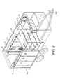
- the control center 12 is housed in a trailer 150 (see Fig. 4), which allows for ease of transportation and mobile installation of the system 10 near the structure where fish control is desired.
- the control center 12 is physically divided into different areas: an area housing the system control unit 5, a series of motherboard racks 8 which accommodate the flash head control units 99, and an area for mounting the transformer racks 20, capacitor racks 11 (see Fig. 6), and flash head termination racks 9 (see Fig. 5).
- a flash head 13 may have two or more illumination devices and associated trigger circuits, with the flash head control unit 99 allowing the system operator to switch between illumination devices and circuits to vary the flash wavelength.
- the respective illumination devices xenon tubes 60 on Figs. 25a-25d
- system control unit 5 which preferably includes a personal computer 30 operatively combined with a keyboard 31 and a mouse 33 (as shown in Fig. 1 of the first embodiment) to allow the operator of system 10 to enter system commands.
- the operator can monitor the operation of system 10 by viewing at video display 32 information that is displayed by the software being executed by personal computer 30.
- Data communications to and from system control unit 5 and each flash head control unit 99 are implemented by a serial data communications interface, including communications I/O cable 15.
- the system control unit 5 of the second embodiment is housed in a trailer 150 and is cooled by a roof mounted cooling fan 104 (shown on Fig. 7d).
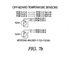
- the temperature inside and outside the trailer 150 is measured via temperature sensors located internal and external to the trailer 150 (two of which are shown schematically as TS101 on Fig. 7b).
- each flash head control unit 99a, 99b, 99c, 99d, and 99e electrical power is provided to each flash head control unit 99a, 99b, 99c, 99d, and 99e from a power interface panel 14 having a power input cable 19 connected to a conventional A/C power supply at the location of the structure, with operational power then being delivered to each flash head control unit 99 by power output cables 18.
- Electrical power is provided in the second embodiment of the system 10 from a conventional power interface panel (not shown) having a power input cable 18 connected to a conventional A/C power supply 120 (Fig. 3) that is either provided at the location of the structure or is a conventional A/C power supply generator that travels with the system 10, with operational power then being delivered to the control center 12 by power cable 18.
- the second embodiment of the system 10 further includes a power transformer bank 21 (Fig. 7a) that comprises three transformers T12, T13, and T14 connected in parallel that serve as the primary power source for the system 10.
- Power transformer bank 21 can further be comprised of a single transformer capable of providing power for the system 10 instead of a bank of three transformers.
- An auxiliary power transformer T11 is also included to serve as auxiliary power source for the system 10.
- the auxiliary power transformer is switched in and out of a flash head interface circuit 96 to increase or decrease the power output to the capacitor bank 23 as required by the system 10.
- the connections for providing power to the motherboards and daughter cards of the system are shown in Fig. 7c.
- the system 10 of both embodiments also includes a conventional air compressor 112 (shown in Fig. 3 of the second embodiment) which has an "on/off" control input, connected to an output relay (not shown) in a flash head control unit 99 in the first embodiment and with the control center 12 of the second embodiment, with an air line 71 (Fig. 27) extending into the water around the system 10.
- a conventional air compressor 112 shown in Fig. 3 of the second embodiment
- an output relay not shown
- a flash head control unit 99 in the first embodiment
- the control center 12 of the second embodiment with an air line 71 (Fig. 27) extending into the water around the system 10.
- the air bubbles 72 enhance light dispersion and reflection, making the strobed lights more visible to the fish.
- a conventional water pump 105 (shown in Fig. 3 of the second embodiment) can also be used in conjunction with either embodiment of the system 10, the purpose of which is to supply high pressure water to a water jet 74 (Fig. 27) directed at the lens area of each flash head 13.
- the water jets can be used to remove scum that may build up on the surface of lens 57.
- a temperature probe 77 is shown positioned in the water near mounting rack 70 and a flash head 13. Probe 77 provides ambient water temperature data to system control unit 5 for use as described below.
- system control unit 5 An important aspect of the system 10 of both embodiments is the high level of control and monitoring provided by system control unit 5. Coordinating and controlling communications to and from all subsystems, the system control unit 5 provides both overall control and complete monitoring of all aspects of system operation. At least one system control unit is required per system 10. The system control unit 10 performs the following functions:
- the system control unit 5 includes the following external inputs: communications with the flash heads 13; communications with remote control/monitoring software via modem and analog phone line; input from one or more temperature probes 77 and sensors TS101; computer keyboard 31 and mouse 33.
- each system control unit 5 has provisions for the following external outputs: communications with the flash heads 13; communications with remote control/monitoring software; a video display 32; a printer (not shown); and relays (or similar device) to turn on/off the air compressor 112 and water pump 105.
- the system control unit 5 is under the control of software designed for system 10 that, subject to system commands entered by the operator, includes routines to provide the following control services: print/display status report; log system activity to a printer; and enable/disable flashing on one, multiple or all flash heads 13; allow the configuration and initiation of flashing lights on separate flash heads 13 in a operator selected sequence; change flash intensity on one, multiple or all flash heads 13; turn air compressor on/off for bubble curtain output at flash heads 13; turn water pump on/off for water jet output at flash heads 13; turn flash head cooling fan 51 on/off on one, multiple or all flash heads 13; and generate alarms/warnings (including communications errors) for all parts of the system 10 that include the time, date, location and description of the malfunction (when the disruption has been repaired, the alarm listing is removed from the list).
- the system control unit software also preferably includes monitoring routines to provide the following monitoring and reporting services: water temperature at each flash head 13; flash intensity at each flash head 13; and internal flash head 13 temperature.
- the video display 32 of the system 10 of the second embodiment shows the configurations and status of the control center 12 and flash heads 13 in a tabular format providing for quick access and comparison of information.
- the screens can further be modified to accommodate several flash heads 13 to be monitored simultaneously.
- each flash head 13 contains an illumination device and related hardware used to attract and deter fish in conjunction with its corresponding flash head interface circuit 96 (shown in Fig. 3 of the second embodiment) located in a flash head control unit 99.
- a system 10 will contain multiple flash heads 13 to adequately cover the area being serviced.
- the exact number of flash heads 13 used is dependent on many system parameters including the width and depth of the body of water, the system orientation to the body of water, and the relative locations of the areas where fish are to be directed away from and towards.
- each flash head 13 is electrically connected via power and control cable 17 to its respective flash head interface circuit 96 in a flash head control unit 99 (shown in Fig. 1), and operatively connected to system control unit 5, to coordinate its activities with other flash heads 13 and to provide operational monitoring feedback.
- Each flash head 13 of the first embodiment will preferably include the following external inputs: communications with its flash head control unit 99 (via cable 17, and including cooling fan control signals, and flash tube A and B trigger signals); water temperature; and internal flash head temperature.
- Each flash head 13 has provisions for the following external outputs: communications with a flash head control unit 99 (cable 17, including flash head temperature and water temperature).
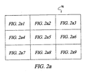
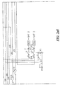
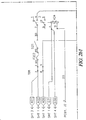
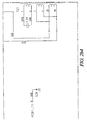
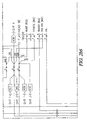
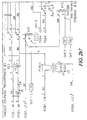
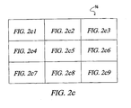
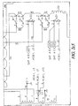
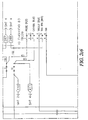
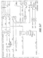
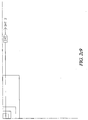
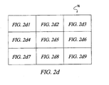
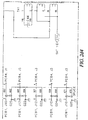
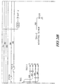
- Figs. 2a, 2b, 2c, and 2d collectively are an electrical schematic of the analog circuitry in single flash head control unit 99 of the first embodiment.
- Fig. 32 is a block diagram of the digital section of the flash head control unit 99, also referred to as the timing and trigger board PCB1.
- the connections to the timing and trigger board PCB1 are labeled on Figs. 2a, 2b, 2c, 2d as "PCB1, Jx", where x corresponds to a connector pin.
- a single flash head control unit 99 is configured to provide power to and communications with up to eight attached flash heads 13, represented in Figs.
- a single flash head housing 56 will enclose one flash tube 60 with related triggering circuitry.
- a flash head 13 will include one flash tube 60 having its own flash head interface circuit 96 within flash head control unit 99. Therefore, there will be a total of eight flash head interface circuits 96, selectable between four flash heads A or four flash heads B, in a single flash head control unit 99 of Figs. 2a, 2b, 2c, and 2d. Applicant herein will describe the interconnection and functioning of a single flash head interface circuit 96, as illustrated on Fig.
- flash head interface circuits 96 illustrated also on Figs. 2b, 2c, and 2d.
- multiple flash tubes 60 with associated trigger circuitry can be installed in a single housing 56 and controlled in a similar manner.
- FIG. 2a1-9 conventional 120 VAC electrical power is supplied to each flash head control unit 99, from power interface panel 14, through a power cable 18, connected at terminal block TB201.
- Input power sense board PCB6 (Fig. 32) senses the presence of input power being supplied to flash head control unit 99 and sends a signal accordingly to system control unit 11. Input power is then distributed to various points as shown throughout flash head control unit 99, beginning with interconnections at terminal block TB8.
- AC power is sent to first high voltage rectifier board PCB12 which is connected at terminal block TB13.
- Lamp 1201 provides visual indication of power being energized.
- timing board PCB1 and temperature sense board PCB4 for example, the 120 VAC supply is stepped down as needed at power transformer T11.
- Fuse F201 provides current overload protection and switch S11 is a safety interlock device that removes power when the front panel of the flash head control unit 99 is opened.
- a bank of capacitors C11A, C11B, C11C, C12, and C13 is provided, in conjunction with capacitor select relays K11 and K12, as a means for selectably adjusting the flash intensity of the corresponding flash head 13.
- Table I shows the range of selectable flash rates, corresponding to different capacitor selections and power settings.
- system operator can enter a system command at system control unit 5 which selects a particular flash intensity as part of the flash head configuration routine.
- the flash intensity selection is implemented by a corresponding flash intensity select signal being sent to relays K11 and/or K12.
- the software in system control unit 5 is pre-programmed with the parameters set forth in Table I which determine the safe operational limits of the particular flash head 13 to avoid overheating of the flash tube. Accordingly, the system control unit 5 internally monitors the configuration of each flash head 13 to prevent selection of flash head operational parameters which would expose the flash tube to an overheating condition. Subject to these limits, in a preferred embodiment of system 10, each flash head can be operated from between 20 to 800 watts with the flash rate adjusted on real time basis from between 60 to 600 flashes per minute. Depending on local ambient and operating conditions, on-site adjustment of the system may be needed to deal with heat management issues. If overheating of the flash heads becomes a problem, a preferred method of solving the problem is to reduce flash head duty cycle by increasing the number of flash heads 13.
- a trigger coupling transformer T13 receives flash trigger signals from timing and trigger board PCB11 (Fig. 32).
- the flash trigger signals are transmitted to either flash head A1 (flash head 13A) connected at terminal block TB203 or to flash head B1 (flash head 13B) connected to terminal block TB207.
- Selection of either flash head A1 or flash head B1 on Fig. 2a is made by trigger and fan steering relays K15 and K16 which are responsive to flash head select signals received from timing and trigger board PCB11.
- a flash tube current sense transformer PCB14 has its primary winding connected to the anode of each flash tube within flash head A1 and flash head B1.
- the secondary winding of flash tube current sense transformer PCB14 is connected to timing and trigger board PCB11 so that an appropriate signal can be sent to system control unit 5, verifying functioning of the flash tube.
- Steering relays K15/K16 also control the switching of data from corresponding temperature sensors TS101 associated with flash head A1 or B1, which is electrically connected at terminal block TB211. This data, preferably generated from a conventional thermistor type sensor, is then sent to temperature sensing board PCB4. Also, flash head fan sense module PCB15 confirms operation of a corresponding flash head fan (fan 51 on Fig. 18b), sending a confirming signal to timing and trigger board PCB11.
- Power selection relay K1 in response to a signal from timing and trigger board PCB11, varies the operating power in response to flash rate and intensity selections.
- a tuning capacitor C14 is connected across a primary winding of power transformer T11 to assist in regulation of the secondary output voltage.
- Discharge relay K4 unless closed by a signal from timing and trigger board PCB11, enables flashing of each flash head 13 connected to flash head control unit 99, by allowing discharge of current from a corresponding flash tube 60 through discharge resistor R1.
- Fig. 2c also schematically illustrates the serial data communications connections to the flash head control unit 99.
- the data is transmitted and received using an industry standard RS485 serial communications link and protocol, connected at terminal blocks TB213 and TB214, with the data being sent to and received from timing and trigger board PCB11.
- Fig. 2d schematically shows a series of six blowers B1, B2, B3, B4, B5, and B6 which work together to internally circulate and exhaust air from flash head control unit 99.
- Operation of blowers B1 - B6 is controlled by blower control relays K8 and K9 in response to signals received from timing and trigger board PCB11 .
- Fig. 32 illustrates the various functional blocks of timing and trigger board PCB1 and their interconnection.
- Basic flash head control is provided by a conventional microprocessor 80 which receives analog data input from the various analog sensors in the system 10, shown as block 81, and performs a multiplexed analog-to-digital conversion of that data (flash head temperature, capacitor bank voltage, line voltage, trigger voltage, and flash sensing) of the system 10 to configure and adapt processor 80 to perform the functions required by the system.
- a random access memory chip 83 provides static memory for use of processor 80 while a read only memory chip 84 (EPROM) contains the software which provides the basic operating system functions for the processor 80.
- EPROM read only memory
- the outputs from processor 80 to system 10 are provided through decoder block 85 and latch block 86. These in turn provided trigger signals through trigger circuit 90 to trigger operation of flash tubes 60 in the various flash heads 13, through the circuitry shown on Figs. 2a-2d. Visual indication of operation of the system is also provided through a light emitting diode block 91. Finally, control of the various system signals for operation of system accessory devices, specifically the air compressor and water pump, are provided through accessory control block 92. Serial communications between the timing and trigger board PCB11 and the system control unit 5 are provided through a serial communications interface 87, which includes both a standard RS232 system diagnostics port 89 and a conventional RS485 serial port 88.
- Interface output connector 95 mechanically and electrically connects the outputs from timing and trigger board PCB1 to the other corresponding sections of system 10.
- Power for timing and trigger board PCB11 is provided through a power supply and reset circuit 93 which sends power reset and interrupt signals to the processor 80 at start up and reset of system 10.
- Analog input signals are provided to timing and trigger board PCB1 through input interface connector 94.
- each flash head 13 is mounted together with two other flash heads 13 to form a tri-pack of flash heads 13, as described below.
- Each tri-pack of flash heads 13 is electrically connected via a single power and control cable 17 to a flash head termination rack 9, which is further connected to a flash head control unit 99 mounted in part on a motherboard.
- the flash head termination rack 9 provides a connection between flash head control unit 99 and the flash heads 13.
- Each flash head 13 preferably includes the following external inputs: communications with its corresponding flash head control unit 99 (via cable 17 and termination rack 9), and including cooling fan control signals, and flash tube trigger signals; water temperature; and internal flash head temperature.
- Each flash head 13 has provisions for the following external outputs: communications with flash head control unit 99 (via cable 17), including flash head temperature and water temperature.
- Figs. 7a, 7b, 7c, and 7d are collectively an electrical schematic of the analog circuitry of a flash head interface circuit 96 of the second embodiment of the system 10.
- the flash head interface circuit 96 is used by the flash head control unit 99 to control the illumination of one tri-pack of flash heads 13 connected to the termination racks 9. Since each flash head control unit 99 is configured to control fifteen flash heads 13, each flash head control unit 99 has five flash head interface circuits 96 identical to the one in Fig. 7a. Each flash head interface circuit 96 is therefore connected to the motherboard of the flash head control unit 99.
- Fig. 23 is a block diagram illustrative of the digital section of the flash head control unit 99, also referred to as the timing and trigger board PCB11.
- the connections to the timing and trigger board PCB11 are labeled on Fig. 7a as "PCB11, Jx(Jy - z)", where x corresponds to a connector pin on the motherboard, y corresponds to a phoenix connector for the daughter card with the motherboard, and z corresponds to the pin number on the phoenix connector.
- a single flash head housing 56 will enclose one flash tube 60 with related triggering circuitry.
- the system 10 will be able to control up to 90 flash heads 13 in 30 total tri-packs.
- Applicant herein will describe the interconnection and functioning of a flash head interface circuits 96 of the second embodiment, as illustrated on Figs. 7a-7d, with the understanding that the same description applies as well to the remaining flash head interface circuits 96 of the other flash head control units 99.
- multiple flash tubes 60 with associated trigger circuitry can be installed in a single housing 56 and controlled in a similar manner.
- Figs. 7a and 7d conventional 120 VAC electrical power is supplied to each flash head interface circuit 96 through a power cable 17 connected at the breaker panel. Input power is distributed to the flash heads 13 as determined by relays K11 and K12. For those circuits and components requiring a DC supply voltage, AC power is sent via power transformer bank 21 (transformers T11-T14) to terminal block TB12, which is connected to high voltage rectifier board PCB14. For devices and components needing AC supply voltage, the 120 VAC supply is also stepped down as needed at power transformer bank 21 (transformers T11-T14).
- tuning capacitor bank 22 including tuning capacitors C11, C12, C13, and C14, is connected across the primary windings of power transformers T11, T12, T13. and T14 of power transformer bank 21 to assist in regulation of the secondary output voltage to each flash head 13.
- Trigger capacitor bank 23 contains capacitors C15-C19 that are used in conjunction with capacitor select relays K13 and K14 as a means for selectably adjusting the flash intensity of the corresponding flash head 13.
- Table I shows the range of selectable flash rates, corresponding to different capacitor selections and power settings.
- the system operator can enter a system command at the system control unit 5 to select a particular flash intensity as part of the flash head configuration routine.
- the flash intensity selection is implemented by a corresponding flash intensity select signal being sent to relays K13 and/or K14.
- the software in the system control unit 5 is pre-programmed with the parameters set forth in Table I which determine the safe operational limits of the particular flash head 13 to avoid overheating of the flash tube 60. Accordingly, the system control unit 5 internally monitors the configuration of each flash head 13 to prevent selection of flash head operational parameters which would expose the flash tube 60 to an overheating condition.
- the second embodiment of system 10 works similar to the first embodiment of the system 10 in that each flash head 13 can be operated from between 20 to 800 watts with the flash rate adjusted on real time basis from between 60 to 600 flashes per minute. Depending on local ambient and operating conditions, on-site adjustment of the system may be needed to deal with heat management issues. If overheating of the flash heads 13 becomes a problem, a preferred method of solving the problem is to reduce flash head duty cycle by increasing the number of flash heads 13.
- a flash tube current sense transformer PCB13 has its primary winding connected to the anode of terminal block TB11.
- the secondary winding of flash tube current sense transformer PCB13 is connected to timing and trigger board PCB11 so that an appropriate signal can be sent to the flash head interface circuit 96, verifying functioning of each flash tube 60 of the tri-pack configuration.
- the cathode of terminal block TB11 is further connected to terminal block TB12.
- the flash heads 13 are connected in parallel to the cathode and anode of terminal block TB11 which triggers each of the three flash heads 13 of the tri-pack configuration according to the current supplied.
- Transformers T15-T17 of triggering transformer bank 24 are connected to trigger ports 1-3 of terminal block TB11 to provide power to each flash head 13 according to the duration and intensity desired. Furthermore, because the current supplied to each flash head 13 is provided through the parallel connection to terminal block TB11, each flash head 13 operates on one-third of the duty cycle that would be applied for a single connection to one flash head 13.
- flash intensity signals originate from timing and trigger board PCB11 and are sent to relays K13 and K14, which determine the intensity and duration of each flash by the current supplied to the ports of terminal block TB11.
- the temperature sensors TS101 (shown schematically in Fig. 7b) associated with the flash heads 13 are connected at the flash head termination rack 9 with the flash head interface circuit 96.
- the temperature sensors (preferably conventional thermistor type sensors) provide temperature data from each individual flash head 13. This data is sent to temperature sensing board PCB12 for analysis by the system control unit 5.
- Fig. 32 illustrates the various functional blocks of timing and trigger board PCB11 and their interconnection.
- Basic flash head control is provided by a conventional microprocessor 80 which receives analog data input from the system 10, shown as block 81, and performs a multiplexed analog-to-digital conversion of that data (flash head temperature, capacitor bank voltage, line voltage, trigger voltage, and flash sensing) of the system 10 to configure and adapt processor 80 to perform the functions required by the system.
- a random access memory chip 83 provides static memory for use of processor 80 while a read only memory chip 84 (EPROM) contains the software which provides the basic operating system functions for the processor 80.
- An electrically erasable read-only memory chip (EEPROM) stores the system's configuration in the event of a power loss.
- the outputs from processor 80 to system 10 are provided through decoder block 85 and latch block 86. These in turn provide trigger signals through trigger circuit 90 to trigger operation of flash tubes 60 in the various flash heads 13. through the flash head interface circuit 96 shown on Fig. 7a.
- control of the various system signals for operation of system accessory devices, specifically the air compressor 112 and water pump 105, are provided through accessory control block 92.
- Serial communications between the timing and trigger board PCB11 and the system control unit 5 are provided through a serial communications interface 87, which includes both a conventional RS232 system diagnostics port 89 and a conventional RS485 serial port 88.
- Interface output connector 95 mechanically and electrically connects the outputs from timing and trigger board PCB11 to the other corresponding sections of system 10.
- Analog input signals are provided to timing and trigger board PCB11 through input interface connector 94.
- Figs. 16-27 illustrate the structure and internal arrangement of components used with flash head 13 used in both embodiments of the system 10. Because in a typical installation of system 10, each flash head 13 will be submerged in a body of water associated with a fixed structure to be protected by the system 10, each flash head 13 includes a water proof protective outer housing 56 (shown in Fig. 16) having an opening at one end covered by a light transmissive lens 57 sealed with a circumferential retaining ring 58, a lens shim 73, and o-ring seal 75.
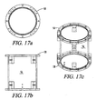
- the housing 56 (see Fig. 17a, 17b, and 17c) will be fabricated from type 6061 Aluminum.
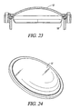
- the lens 57 is made of tempered borosilicate glass, and is curved so as to provide the most effective distribution of light (see Fig. 23).
- the lens 57 can be made with a diffraction pattern (see Fig. 24) to effectively disperse light in a short, broad pattern or with a clear, refractive mechanism to penetrate a greater distance with the light.
- a water tight cable fitting 54 extends from and through housing 56 to allow for entry of the power and control cable 17.
- Two parallel plates 55 are welded to housing 56 as trash shields and to protect cable fitting 54.
- a gas fitting 76 is also provided to allow for air/gas (including nitrogen gas) injection and evacuation if desired.
- flash head 13 The selection and arrangement of components internal to flash head 13 illustrates some of the novel features of system 10, as implemented in flash head 13, which optimally adapts the flash heads 13 for extended use in a submerged environment.
- the flashed illumination from flash head 13 is provided by a flash tube 60, preferably a xenon flash tube, supported by a flash tube mount 46 (Fig. 25a-25d) and enclosed within a protective Pyrex glass cylinder 49.
- Each flash tube 60 will include three rigid electrical connections attached to flash tube mounting lugs 7 supported by flash tube mount 6 (Fig. 18b). The electrical connections are anode 61, cathode 62, and trigger input 63.
- an electrically powered fan 51 (typically a squirrel cage fan) is mounted below flash tube 60 to force air around flash tube 60 through a Pyrex glass air duct 59.
- the fan 51 is mounted to the inner portion of the bottom wall of enclosure 56 by blower base plate 52.
- An annular parabolic reflector 53 (shown in Figs. 22a and 22b) circumferentially surrounds flash tube cylinder 49 to maximize the amount of light directed outward of flash head 13 through lens 57.
- parabolic reflector 53 includes a centrally disposed annular opening to allow passage of air duct 59, thus minimizing the loss of light due to impairment of the reflective surface. Also, the parabolic reflector 53 is preferably coated with Everbrite 95® to give a reflectivity of 95%.
- anode and cathode leads 61 and 62 have an enlarged diameter, preferably approximately 0.100 inches.
- a pair of heat sink fins 65 extend radially outward from leads 61 and 62.
- a shroud 48 and reflector 53 forms an air plenum around flash tube 60.
- the diameter of plenum shroud 48 is selected so that when installed, an air passageway 64 is defined between the outer surface of plenum shroud 48 and the inner surface of flash head enclosure 56. Accordingly, air or nitrogen circulated within flash head 13 by fan 51 (Fig. 20) is forced through air passageway 64 where it is cooled by coming into contact with housing 56. Enclosure 56 is itself cooled by the effects of ambient water temperature when flash head 13 is submerged.
- Mounting brackets 43 mechanically attach parabolic reflector 53 to plenum shroud 48.
- the blower 51 will preferably have a rating of at least 55 CFM at a static pressure of 0.4 inches of water.
- the air contained inside the flash head housing 56 is replaced by nitrogen gas, which negates the corrosive effect of ozone in the flash head housing 56.
- Flash tube mount 46, shroud 48 and blower 51 are secured to a sheet metal weldment 42.
- the weldment 42 is attached to three support posts 65 (Fig. 19) welded to housing 56.
- Flash head electrical components shown in part on Figs. 18a and 18b, and schematically described on Fig. 21, are electrically connected to one or more ceramic posts 44 arranged around and attached to the bottom wall of plenum shroud 48.
- Temperature sensor TS101 provides electrical signals responsive to the internal flash head temperature for use by system control unit 5 in monitoring and regulating the operation of each flash head 13.
- the safe internal temperature operating range is 14 - 122 degrees F.
- a pair of opposed heat shields 45 extend vertically from the lower wall of plenum shroud 48 and up along the outer wall of duct 59 to a distance above the upper margin of the installed electrical components.
- Fig. 21 is a schematic diagram of the electrical components and interconnections in flash head 13.
- a series of wire terminals P1 through P11 (each of which corresponds to a ceramic post 44 on Fig. 18a) provide a connection point for the individual flash head power and communication wires contained within flash head power and control cable 17 (Figs. 1 and 3).
- flash tube power is brought to the anode and cathode of flash tube 60 through terminals P1 and P2, respectively.
- the cathode power from flash head control unit 99 is also connected to the secondary winding on trigger transformer T101, through an R-C filter network RC101.
- the flash tube trigger signal is received from flash head control unit 12 at terminals P3 and P4 and, through de-coupling transformer T102, drives the primary winding of trigger transformer T101 connected at terminals P8 and P9.
- Terminals P4 and P5 of flash head 13 provide power to fan 51, at blower motor start-up capacitor C101. Finally, temperature data is transmitted back to flash head control unit 5 from temperature sensor TS101 through wires terminating in terminals P10 and P11.
- Fig. 19 shows the physical location within flash head 13 of the wire terminals P1 through P11 and the other electrical components of Fig. 21.
- Fig. 28 illustrates the flash head 13 configuration for the second embodiment.
- the flash heads 13 are mounted together in groups of three as a tri-pack on a flash head mounting plate 14, with the electrical connection between each flash head control unit and each flash head tri-pack being a single cable 17.
- the mounting plate 14 has three circular indentations 16 at each of the three corners that allows for secure locking of the circular flash head housing 56 to the mounting plate 14.
- the arrangement of the flash heads 13 in a triangular shape allows for the most effective dispersion of light while under water. Further, by using the tri-pack arrangement of flash heads 13, each flash head 13 of the tri-pack will be illuminated during one-third of a standard illumination duty cycle.
- the system 10 can produce faster flash rates than when each flash head 13 operated using the entire duty cycle. This furthermore reduces the operation time of the individual flash heads 13 by two-thirds, which allows for increased reliability of the flash tubes 60 and longer life for the flash tubes 60.
- the communications in the first embodiment between the system control unit 5 and the flash head control units 99, one for each group of 1 to 32 flash heads 13, will consist of a standard RS-485 2-wire communications link. There will be a separate link for each flash head control unit 99.
- the control center 12 has two serial communication interfaces for interconnecting to a host computer and running diagnostics.
- the first port is based on the RS485 standard and allows any number of computers to be daisy-chained to the system control unit 5 for configuration and data collection.
- a second communication port is based on the RS232 standard and is used for interfacing to the serial port of the personal computer of the system control unit 5 in order to run diagnostics by utilizing any type of terminal emulator.
- the communications between the system control unit 5 and the flash head control unit 99 will consist of a standard RS-485 2-wire communications link.
- Each message will have the following Message Format:
- the communication scheme requires most messages to be acknowledged upon receipt. Messages requesting a response will accept the response as the acknowledgment. Other than broadcast or poll messages, messages not requesting a response require a separate ACK (message acknowledged) or NAK (message not acknowledged) to be sent. Broadcast messages are addressed to all devices so there is no use in one particular device responding. Poll Messages are sent by the system control unit 5 to a flash head control unit 99 to determine whether the flash head control unit 99 has new or changed information pending (i.e. an alarm or warning condition that has occurred). If a flash head control unit 99 has no information pending, it can ignore (not respond to) a Poll Message. If it has information pending, it should send the message when it receives a Poll.
- ACK or NAK responses are based on several items: 1) correct checksum received; 2) correct #-of-bytes received (matches message length); 3) no communications errors detected (parity error, SW or HW overrun errors, etc.).
- ACKnowledging (or NAKing) the receipt of a message is performed regardless of whether the message type is processed by the receiving unit. This allows new messages to be created for other devices on the same communications link without modifying the software in all units.
- the capability to send variable length messages also allows new information required for one type of system control unit 5 to be added to an existing message without changing the software in all units. System control units 5 without upgraded software will only process the information they know about and will ignore new information added to the end of the message.
- Communications messages from the system control unit 5 to the flash head control units 12 will include:
- the communications from each flash head control unit 99 to the system control unit 5 include:
- GUI graphical user interface
- the mouse selectable options available to the user on this screen include the enabling or disabling of a particular flash head 13 attached to that flash head control unit 99, establishing the communications port location for that flash head control unit 99, establishing the system address, enabling or disabling trigger and transformer monitoring functions, and enabling or disabling operation of the exhaust, circulation, and heat sense fans (blowers B1 - B6).
- Fig. 9 is the GUI screen presented to the operator for configuration of the flash sequence involving all of the flash heads 13 attached to system 10. During this operation, the operator can set the flash order, flash timing, flash spacing, and similar sequence parameters.
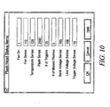
- Fig. 10 is the GUI screen presented to the operator at the time of configuration of a specific flash head 13, connected to a particular flash head control unit 99.
- the operator can either use overall system settings for the flash head or override the system settings, including selection of flash color (flash head A or B), flash rate, flash sequence delay, flash intensity, and (optionally) flash head position, which is adjusted using water jets (not shown) associated with that flash head 13.
- flash head triggering can be enabled or disabled as well as flash head cooling fan 51 operation.
- Fig. 11 is the GUI screen presented to the operator at system control unit 5 (or at a remote control location) reporting the status and function history of a particular flash head 13 over a particular operational interval.
- GUI graphical user interface
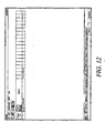
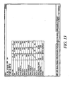
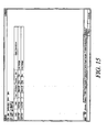
- the tabular format (shown in Figs. 12, 13, 14. and 15) allows the user to see the various controls at the bottom of the screen and allows for quick access of information, and further allows easy access to each section of control information for comparison to other values by using the mouse to choose the desired tab.
- Figs. 12-15 illustrate typical GUI screens presented to the system operator at video display 32.
- Fig. 12 is the GUI screen that would be used by the operator when checking the status of a flash head 13.
- Fig. 13 is the GUI screen presented to the operator for monitoring real time data for one flash head 13 of the tri-pack.
- Fig. 14 is the GUI screen presented to the operator that displays a typical status screen monitoring real-time data for a single transformer bank.
- Fig. 15 is the GUI screen presented when there is a system alarm. The alarms displayed are removed from the list automatically once the alarm has been acknowledged by the operator or once the malfunctioned element is repaired.
- system 10 and system control unit 5 of both embodiments will be configured for optional remote operation by use of remote control and monitoring software installed on a personal computer that allows a user to dial into (via modem and telephone line), control and monitor system 10 from a remote location.
- This program can be used in place of or in addition to on-site personnel located at a system control unit 5 located at the system site.
- the remote control and monitoring software handles the same communications and provides the same level of control and monitoring as the software used at system control unit 5.
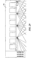
- Figs. 29, 30, and 31 illustrate a typical installation of both embodiments of the system 10 near the underwater portion of a hydroelectric facility 100, including four turbine intakes.
- Four flash head mounting racks 70a, 70b, 70c, and 70d extend vertically down the side wall of the structure 100.
- Each flash head mounting rack 70 supports multiple flash heads 13 to provide a preferred pattern of flash illumination for fish who may approach the structure.
- a plurality of flash head control units 99 are attached on top of the structure 100 proximate the flash head racks 70 and connected by cables 15 and 17 (Fig. 1).
- the end portions of racks 70 are not submerged are attached to structure 100 in a hinged arrangement flash heads 13 can be accessed above water for any maintenance needed.
- the trailer 150 containing the control center 12 is located near the top of the structure 100 and connected to the tri-packs of flash heads 13 by cables 17.
- the tri-packs of flash heads 13 are bed-railed to flash head mounting racks 70a, 70b, 70c, and 70d that extend vertically down the side wall of the structure 100.
- Each flash head mounting rack 70 supports multiple tri-packs of flash heads 13 to provide a preferred pattern of flash illumination for fish who may approach the structure.
- the end portions of the racks 70 for both embodiments are not submerged and are attached to the structure 100 in a hinged arrangement so that the flash heads 13 can be accessed above water for any maintenance needed.
- the flash heads 13 are operated at three hundred forty (340) flashes per minute with a typical flash intensity of 400 watts.
- turbine intakes 3 and 4 on Fig. 30 have fish bypass areas that allow for safe passage, fish can be guided to those areas by flashing the flash heads 13 on the flash head racks 70 adjacent to turbine intakes 1 and 2 together.
- the flash intensities of the flash heads 13 on the flash head racks 70 adjacent to turbine intakes 3 and 4 can be gradually decreased as the depth is decreased, directing the fish upward towards the safe passage area.
Landscapes
- Life Sciences & Earth Sciences (AREA)
- Environmental Sciences (AREA)
- Marine Sciences & Fisheries (AREA)
- Animal Husbandry (AREA)
- Biodiversity & Conservation Biology (AREA)
- Farming Of Fish And Shellfish (AREA)
- Stroboscope Apparatuses (AREA)
- Optical Communication System (AREA)
- Circuit Arrangement For Electric Light Sources In General (AREA)
- Mechanical Means For Catching Fish (AREA)
Description
- The present invention relates generally to barriers and other devices used to repel or direct the movement of migrating fish away from turbine intakes and other danger points at dams, hydroelectric facilities, and water intakes in lakes and rivers. More particularly, the present invention describes a system for directing the movement of fish in which the system uses multiple underwater strobe lights strategically positioned and controlled to direct fish away from and towards desired locations.
- Hydroelectric power plants and dams have been used throughout the United States and the world with great effectiveness in electric power generation, irrigation, and flood control schemes. However, the increasing use of obstructions across rivers and other navigable waterways has created problems of its own, including deleterious effects on fish populations. For example, hydroelectric dam turbine intakes are a natural attraction point for schooling and migrating fish. If fish are allowed to enter those intakes, large numbers of fish are killed in relative short periods of time. Such fish kills, in turn, can cause damage to the facilities themselves. Also, dams and other structures placed across rivers can interfere with the natural migratory patterns of fish that have been established over the years. If these fish are not allowed to pass the dam and are obstructed from following their natural migratory waterways, fish populations can be greatly impaired. Similar problems can occur at municipal and industrial water intake sites, where large numbers of fish can be drawn into the intake. Therefore, it is important that some means be provided to direct migrating fish around or through a dam, obstruction, or intake so that they can reach their natural spawning grounds.
- In response to these issues, federal and state agencies have become increasingly active in establishing a regulatory scheme for the protection of fish in these environments. Accordingly, a variety of physical barrier technologies have been developed in the prior art. These prior art technologies include the use of barrier nets, fish lifts, racks, mesh screens, and louvered bypasses. Unfortunately, such physical barriers have not been optimally efficient in protecting or diverting fish. Moreover, the installation of physical barriers can be extremely expensive, in that custom barrier designs must be developed for each location. Ongoing maintenance costs are also a significant negative factor in the use of physical barriers to control fish.
- As an alternative to the use of physical fish barriers, experiments have been conducted in the prior art in the use of strobe lighting as a means to repel fish or otherwise control or direct their movement as they confront or approach a dam or other water intake. These experimental studies have demonstrated that strobe lights produce strong avoidance behavior in a variety of fish species on a consistent basis. In addition, the fish who show this avoidance behavior do not show a tendency to become acclimated to strobe light stimuli, even after prolonged exposure.
- The strobe light systems used in the prior art experiments for the control of fish behavior have been deficient in a number of respects, particularly in regards to the development of a commercially useful system which can be easily adapted, installed, and used in a wide variety of physical and aquatic environments and that can be used, without significant modification, to control the behavior of one or more of multiple fish varieties. Thus, for example, variations in ambient water turbidity, water flow rate, flow direction, and water temperature, can directly impact the efficiency of fish control using strobe light systems. In addition, experimentation relating to the development of the present invention has shown that adjustment of flash intensity, flash frequency, and flash sequence is necessary in order to optimally adapt a strobe light fish control system to a particular environment and to a particular species of fish. Prior art systems have not allowed this degree of flexibility and control leading, to the conclusion that such systems can only be considered to be experimental rather than commercially useful.
- For behavioral control of fish during a short migration season, there is only a very narrow window of opportunity to adapt a strobe light control system to that species of fish and to the particular environmental conditions encountered. Therefore, real time reaction and control of the system to varying ambient conditions and fish behavior is an important factor. Such control is not found in any of the prior art experimental systems.
- Furthermore, a short migration season also requires that a system be mobile to be positioned quickly and efficiently by a dam or other structure so as to provide a deterrence or guidance for the fish and then be able to move on to another site.
- Another problem found with prior art strobe light fish control systems relate to the longevity of the crucial underwater portion of the system, that being the multiple strobe light flash heads. Much of the prior experimentation with such systems has been used in conjunction with flash heads mounted at or near the water surface, attached to floating structures. However, a universally adaptable, commercially useable fish control system using multiple strobe flash heads must be capable of installation at significant depths below the water line, up to perhaps one hundred-fifty feet. This produces a set of problems of its own, particularly in heat management. The preferred means of generating illumination from a strobe flash head is the xenon tube which is both durable and highly efficient. However, the heat generated by the xenon tube and related components must be carefully controlled, particularly in an underwater location, so that the flash head will not fail prematurely because of excessive heat buildup. Experimental prior art strobe light fish control systems have relied on relatively crude adaptations of strobe light devices which have not fully met the needs for deep water submersion, durability, and high flash intensity.
- What is needed, then, is a system for the control of fish movement using strobe lights which can be easily installed and adapted to a wide variety of physical environments, can be controlled and adjusted to influence the behavior of a wide variety of fish species, and which carefully deals with flash head heat management in order to prolong the durability of the system.
- One object of the present invention is to provide a system to direct the movement of fish near man-made structures that is reliable, efficient, flexible, easy to install, mobile, and easy to maintain.
- Another object of the present invention is to provide a strobe light fish movement control system in which operational control and functioning of the system can be adjusted easily and in real time to adapt the system to changing water and other conditions near the structure.
- Yet another object of the system of the present invention is to provide flash heads in a multiple flash head strobe light fish movement control system which can operate efficiently and continuously while submerged.
- A further object of the present invention, shown in a second embodiment, is to provide a controllable strobe light system that is easily transportable to locations where control of fish movements may be needed.
- These and other objects of the invention which will be apparent to those skilled in the art are met by two embodiments of a strobe light fish movement control system in which multiple flash heads are linked through one or more flash head control units to a personal computer based system control unit. The system control unit and flash head control units include data communication services, status monitoring devices, and control links which allow an operator of the system to change and monitor the flash sequence, flash rate, and flash intensity. In addition, an air bubble curtain and water jets installed at or near the flash heads allow the system to adapt to changing water conditions and fish varieties so that the system can be easily optimized for a particular environment.
- The flash heads used in the system are configured for long life while submerged through the use of novel heat management features. An internal cooling fan and temperature sensor send signals to the system so that appropriate heat control measures can be undertaken. An air plenum is formed around the flash tube inside the waterproof flash head housing so that air can be easily circulated, with an air passage way formed between the outside of the air plenum and the inner wall of the housing. A parabolic reflector enhances radiated light from the flash head and forms a top surface of the air plenum. Forced air is brought to the flash tube through an opening in the central portion of the parabolic reflector, thereby minimizing light loss. Furthermore, the air present in the flash head housing is replaced by nitrogen gas to reduce the corrosive effect of ozone within the flash head.
- Constant monitoring of flash rate, flash intensity, and flash head temperature prevents overheating of the flash tube in each flash head.
- Fig. 1 is a perspective view showing the general arrangement of the first embodiment of the system of the present invention, including the system control unit, multiple flash head control units, and multiple flash head.
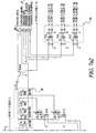
- Figs. 2a1-9, 2b1-9, 2c1-9, and 2d1-9 collectively are a schematic diagram of a flash head control unit as used in the first embodiment of the present invention, with each flash head control unit including four flash head interface circuits which are separately illustrated on each drawing page.
- Fig. 3 is a block diagram showing the interconnection of the various functional units of the second embodiment of the present invention.
- Fig. 4 is a perspective view of the general mechanical arrangement of the power and control center of the second embodiment of the present invention positioned in a mobile trailer, including the flash head termination racks, the capacitor racks, a transformer assembly rack, and the motherboard enclosures (shown in phantom with no components connected).
- Fig. 5 is an enlarged perspective view of a flash head termination rack (the connections to the flash heads not shown) as used in the second embodiment of the system of Fig. 4.
- Fig. 6 is an enlarged perspective view of a capacitor rack as used in the second embodiment of the system of Fig. 4 (no installed capacitors shown).
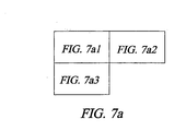
- Fig. 7a1-3 is a schematic diagram of a portion the flash head interface circuit used in the second embodiment of the system showing the power and flash tube trigger connections to the tri-packs of flash heads as well as to the capacitor and transformer banks.
- Fig. 7b is a schematic diagram of a portion of the flash head interface circuit used in the second embodiment of the system showing the connections to two of the system temperature sensors.
- Fig. 7c is a schematic diagram a portion of the flash head interface circuit used in the second embodiment of the system showing the low and high voltage power connections and the trigger power connections.
- Fig. 7d is a schematic diagram of a portion of the flash head interface circuit used in the second embodiment of the system to provide power to the flash head cooling fan motor.
- Fig. 8 is a drawing of a typical video display of a screen generated by the software used in the system control unit of the first embodiment of the system, allowing the user to configure operation of a flash head control unit.
- Fig. 9 is a typical video display screen generated by the software of the system control unit of a first embodiment of the system, illustrating a configuration of the system for all flash heads.
- Fig. 10 is an illustration of a typical video display screen of generated by the software of the system control unit of a first embodiment of the system when monitoring the operational status of a specific flash head.
- Fig. 11 is an illustration of a typical video display screen presented to an operator of a first embodiment of the system at the system control unit when configuring an individual flash head.
- Fig. 12 is an illustration of a typical video display screen of the second embodiment of the system presented to a system operator at the system control unit to display the status of a flash head.
- Fig. 13 is an illustration of a typical video display screen of the second embodiment of the system presented to a system operator at the system control unit for monitoring real time data of a tri-pack of three flash heads.
- Fig. 14 is an illustration of a typical video display screen of the second embodiment of the system presented to a system operator at the system control unit for monitoring real time data for a single transformer bank.
- Fig. 15 is an illustration of a typical video display screen of the second embodiment of the system presented to a system operator at the system control unit when the system is displaying an alarm condition.
- Fig. 16 is an exploded perspective view of a single flash head, showing the lens, parabolic reflector, helical flash tube, squirrel cage fan and lens clamping ring.
- Fig. 17a is a top view of a flash head housing.
- Fig. 17b is a side view of a flash head housing.
- Fig. 17c is a plan view of a flash head housing.
- Fig. 18a is a plan view of the flash head showing the plenum shroud and components internal thereto.
- Fig. 18b is a cut-away side view of a single flash head.
- Fig. 19 is a plan view of the flash head interior to the plenum shroud, with the parabolic reflector removed, showing the location of electrical components and connection terminals.
- Fig. 20 is a view taken along lines 20-20 of Fig. 19. showing the fan portion of the flash head.
- Fig. 21 is a schematic diagram of the flash head electrical system.
- Fig. 22a is a front view of the parabolic reflector.
- Fig. 22b is a side view of the parabolic reflector.
- Fig. 23 is a side view of the lens and parabolic reflector.
- Fig. 24 is a plan view of the lens.
- Fig. 25a is a top view of the helical flash tube.
- Fig. 25b is a side view of the helical flash tube.
- Fig. 25c is a side view of the helical flash tube of Fig. 25b, with the flash tube leads enclosed in a heat resistant glass cylinder.
- Fig. 25d is a bottom view of the helical flash tube.
- Fig. 26 is a cutaway side view of the flash head housing also showing the interior mounting posts.
- Fig. 27 is a perspective view of a single flash head as installed in the system underwater, showing a preferred arrangement of the air bubble curtain and a corresponding water jet.
- Fig. 28 is a perspective view of three flash heads mounted in a tri-pack configuration on a flash head mounting plate.
- Fig. 29 is a plan view showing the flash heads of the system installed proximate a structure.
- Fig. 30 is a front view of the system installation of Fig. 29. showing placement of the flash heads below the water line.
- Fig. 31 is an end view of the installed system of Figs. 29 and 30.
- Fig. 32 is a block diagram of the electrical subsystems associated with the flash head control unit of the first embodiment of the present invention and the flash head control unit of the second embodiment of the present invention, including the timing and trigger board.
- The fish
movement control system 10 is designed to provide an improved solution to the problem of entrainment of aquatic life in structures such as hydroelectric power plant intakes, pumpback station intakes, spillway intakes, and the like. In order to effectively provide deterrence of fish from the varied structures, two embodiments are described: a first embodiment intended for permanent or semi-permanent installation and a second embodiment adapted for mobile transport and operation. - Fig. 1 shows a general arrangement of the first embodiment of the
system 10 prior to installation near the structure where fish control is desired. A set of multiple flash heads 13 operated in a pre-determined sequence provide the strobed illumination used to direct movements of fish when the flash heads 13 are installed underwater near a structure. Eachflash head 13 is connected by a power and controlcable 17 to a flashhead control unit 99. Preferably, to minimize component redundancy and increase the efficiency of installation, multiple flash heads 13 are controlled by a single flashhead control unit 99. Thus, in Fig. 1, a total of twenty flash heads 13 are controlled by five flashhead control units 99a, 99b. 99c, 99d, and 99e. Accordingly, each flashhead control unit 99 will have multiple flashhead interface circuits 96. Signal processing, timing, and trigger control functions are provided by a timing and trigger board PCB1 associated with each flashhead control unit 99, as shown on Fig. 32. - Fig. 3 is a block diagram of the system of the second embodiment of the
system 10. Thesystem 10 of the second embodiment includes a series of sets of multiple flash heads 13 configured in groups of three (called tri-packs) connected to a power andcontrol center 12, with each tri-pack being connected by a single power and controlcable 17 to a flashhead termination rack 9. Thecontrol center 12 includes asystem control unit 5 that determines the rate and intensity that the flash heads 13 are illuminated. - In a second embodiment of the
system 10, thecontrol center 12 is housed in a trailer 150 (see Fig. 4), which allows for ease of transportation and mobile installation of thesystem 10 near the structure where fish control is desired. Inside thetrailer 150, thecontrol center 12 is physically divided into different areas: an area housing thesystem control unit 5, a series ofmotherboard racks 8 which accommodate the flashhead control units 99, and an area for mounting the transformer racks 20, capacitor racks 11 (see Fig. 6), and flash head termination racks 9 (see Fig. 5). - For both embodiments, it may be desired in some aquatic environments to provide illumination wavelengths at each
flash head 13 which are selectable by the system operator, after the flash heads 13 are installed. In those situations, aflash head 13 may have two or more illumination devices and associated trigger circuits, with the flashhead control unit 99 allowing the system operator to switch between illumination devices and circuits to vary the flash wavelength. The respective illumination devices (xenon tubes 60 on Figs. 25a-25d) will have different color filters associated with them so that flash wavelength is selectable. - Overall control functions for both embodiments of the
system 10 are performed bysystem control unit 5. which preferably includes apersonal computer 30 operatively combined with akeyboard 31 and a mouse 33 (as shown in Fig. 1 of the first embodiment) to allow the operator ofsystem 10 to enter system commands. The operator can monitor the operation ofsystem 10 by viewing atvideo display 32 information that is displayed by the software being executed bypersonal computer 30. Data communications to and fromsystem control unit 5 and each flashhead control unit 99 are implemented by a serial data communications interface, including communications I/O cable 15. - The
system control unit 5 of the second embodiment is housed in atrailer 150 and is cooled by a roof mounted cooling fan 104 (shown on Fig. 7d). The temperature inside and outside thetrailer 150 is measured via temperature sensors located internal and external to the trailer 150 (two of which are shown schematically as TS101 on Fig. 7b). - In the first embodiment, electrical power is provided to each flash
head control unit power interface panel 14 having apower input cable 19 connected to a conventional A/C power supply at the location of the structure, with operational power then being delivered to each flashhead control unit 99 bypower output cables 18. - Electrical power is provided in the second embodiment of the
system 10 from a conventional power interface panel (not shown) having apower input cable 18 connected to a conventional A/C power supply 120 (Fig. 3) that is either provided at the location of the structure or is a conventional A/C power supply generator that travels with thesystem 10, with operational power then being delivered to thecontrol center 12 bypower cable 18. - The second embodiment of the
system 10 further includes a power transformer bank 21 (Fig. 7a) that comprises three transformers T12, T13, and T14 connected in parallel that serve as the primary power source for thesystem 10.Power transformer bank 21 can further be comprised of a single transformer capable of providing power for thesystem 10 instead of a bank of three transformers. An auxiliary power transformer T11 is also included to serve as auxiliary power source for thesystem 10. The auxiliary power transformer is switched in and out of a flashhead interface circuit 96 to increase or decrease the power output to thecapacitor bank 23 as required by thesystem 10. The connections for providing power to the motherboards and daughter cards of the system are shown in Fig. 7c. - The
system 10 of both embodiments also includes a conventional air compressor 112 (shown in Fig. 3 of the second embodiment) which has an "on/off" control input, connected to an output relay (not shown) in a flashhead control unit 99 in the first embodiment and with thecontrol center 12 of the second embodiment, with an air line 71 (Fig. 27) extending into the water around thesystem 10. This givessystem 10 the capability of generating an underwater air bubble curtain near one or more flash heads 13 as installed. The air bubbles 72 enhance light dispersion and reflection, making the strobed lights more visible to the fish. - A conventional water pump 105 (shown in Fig. 3 of the second embodiment) can also be used in conjunction with either embodiment of the
system 10, the purpose of which is to supply high pressure water to a water jet 74 (Fig. 27) directed at the lens area of eachflash head 13. The water jets can be used to remove scum that may build up on the surface oflens 57. - Looking further at Fig. 27, a
temperature probe 77 is shown positioned in the water near mountingrack 70 and aflash head 13.Probe 77 provides ambient water temperature data tosystem control unit 5 for use as described below. - An important aspect of the
system 10 of both embodiments is the high level of control and monitoring provided bysystem control unit 5. Coordinating and controlling communications to and from all subsystems, thesystem control unit 5 provides both overall control and complete monitoring of all aspects of system operation. At least one system control unit is required persystem 10. Thesystem control unit 10 performs the following functions: - a. monitor and control serial data communication to and from each flash
head control unit 99; - b. monitor and control communications from a remote control station using the remote control and monitoring software, via a data modem and conventional phone line;
- c. generate and implement a user interface via the
video display 32 to enable the entry of system commands and to report system status. - d. provide on/off control signals to an air compressor for generation of a bubble curtain 72 (see Fig. 27) at each
flash head 13; - e. generate on/off control signals to a
water pump 105 to provide for water jet output at eachflash head 13; - f. generate control signals for flash head cooling devices;
- g. provide control signals to enable/disable flashing of each
flash head 13; - h. configure and control flash head strobe sequence, including sequential ordering, flash spacing, and flash timing;
- i. provide control signals to vary the flash intensity of one or more flash heads 13;
- j. monitor and report water temperature proximate to each
flash head 13; - k. monitor and report flash intensity at each
flash head 13; - The
system control unit 5 includes the following external inputs: communications with the flash heads 13; communications with remote control/monitoring software via modem and analog phone line; input from one or more temperature probes 77 and sensors TS101;computer keyboard 31 andmouse 33. - In addition, each
system control unit 5 has provisions for the following external outputs: communications with the flash heads 13; communications with remote control/monitoring software; avideo display 32; a printer (not shown); and relays (or similar device) to turn on/off theair compressor 112 andwater pump 105. - The
system control unit 5 is under the control of software designed forsystem 10 that, subject to system commands entered by the operator, includes routines to provide the following control services: print/display status report; log system activity to a printer; and enable/disable flashing on one, multiple or all flash heads 13; allow the configuration and initiation of flashing lights on separate flash heads 13 in a operator selected sequence; change flash intensity on one, multiple or all flash heads 13; turn air compressor on/off for bubble curtain output at flash heads 13; turn water pump on/off for water jet output at flash heads 13; turn flashhead cooling fan 51 on/off on one, multiple or all flash heads 13; and generate alarms/warnings (including communications errors) for all parts of thesystem 10 that include the time, date, location and description of the malfunction (when the disruption has been repaired, the alarm listing is removed from the list). - The system control unit software also preferably includes monitoring routines to provide the following monitoring and reporting services: water temperature at each
flash head 13; flash intensity at eachflash head 13; andinternal flash head 13 temperature. - The
video display 32 of thesystem 10 of the second embodiment shows the configurations and status of thecontrol center 12 and flash heads 13 in a tabular format providing for quick access and comparison of information. The screens can further be modified to accommodate several flash heads 13 to be monitored simultaneously. - In the both embodiments of the
system 10, eachflash head 13 contains an illumination device and related hardware used to attract and deter fish in conjunction with its corresponding flash head interface circuit 96 (shown in Fig. 3 of the second embodiment) located in a flashhead control unit 99. In most cases, asystem 10 will contain multiple flash heads 13 to adequately cover the area being serviced. The exact number of flash heads 13 used is dependent on many system parameters including the width and depth of the body of water, the system orientation to the body of water, and the relative locations of the areas where fish are to be directed away from and towards. - In the first embodiment, each
flash head 13 is electrically connected via power and controlcable 17 to its respective flashhead interface circuit 96 in a flash head control unit 99 (shown in Fig. 1), and operatively connected tosystem control unit 5, to coordinate its activities with other flash heads 13 and to provide operational monitoring feedback. - Each
flash head 13 of the first embodiment will preferably include the following external inputs: communications with its flash head control unit 99 (viacable 17, and including cooling fan control signals, and flash tube A and B trigger signals); water temperature; and internal flash head temperature. Eachflash head 13 has provisions for the following external outputs: communications with a flash head control unit 99 (cable 17, including flash head temperature and water temperature). - Figs. 2a, 2b, 2c, and 2d collectively are an electrical schematic of the analog circuitry in single flash
head control unit 99 of the first embodiment. Fig. 32 is a block diagram of the digital section of the flashhead control unit 99, also referred to as the timing and trigger board PCB1. The connections to the timing and trigger board PCB1 are labeled on Figs. 2a, 2b, 2c, 2d as "PCB1, Jx", where x corresponds to a connector pin. In the preferred embodiment ofsystem 10 shown in Fig. 1 and Figs. 2a-2d, a single flashhead control unit 99 is configured to provide power to and communications with up to eight attached flash heads 13, represented in Figs. 2a-2d as flash heads A1, B1, A2, B2, A3, B3, A4, and B4. In this embodiment, a singleflash head housing 56 will enclose oneflash tube 60 with related triggering circuitry. Thus, looking at Fig. 2a, aflash head 13 will include oneflash tube 60 having its own flashhead interface circuit 96 within flashhead control unit 99. Therefore, there will be a total of eight flashhead interface circuits 96, selectable between four flash heads A or four flash heads B, in a single flashhead control unit 99 of Figs. 2a, 2b, 2c, and 2d. Applicant herein will describe the interconnection and functioning of a single flashhead interface circuit 96, as illustrated on Fig. 2a, with the understanding that the same description will apply as well to the flashhead interface circuits 96 illustrated also on Figs. 2b, 2c, and 2d. Optionally,multiple flash tubes 60 with associated trigger circuitry can be installed in asingle housing 56 and controlled in a similar manner. - Looking now at Fig. 2a1-9, conventional 120 VAC electrical power is supplied to each flash
head control unit 99, frompower interface panel 14, through apower cable 18, connected at terminal block TB201. Input power sense board PCB6 (Fig. 32) senses the presence of input power being supplied to flashhead control unit 99 and sends a signal accordingly tosystem control unit 11. Input power is then distributed to various points as shown throughout flashhead control unit 99, beginning with interconnections at terminal block TB8. Thus, for those circuits and components requiring a DC supply voltage, AC power is sent to first high voltage rectifier board PCB12 which is connected at terminal block TB13. Lamp 1201 provides visual indication of power being energized. For devices and components needing AC supply voltage, timing board PCB1 and temperature sense board PCB4, for example, the 120 VAC supply is stepped down as needed at power transformer T11. Fuse F201 provides current overload protection and switch S11 is a safety interlock device that removes power when the front panel of the flashhead control unit 99 is opened. - A bank of capacitors C11A, C11B, C11C, C12, and C13 is provided, in conjunction with capacitor select relays K11 and K12, as a means for selectably adjusting the flash intensity of the
corresponding flash head 13. Table I shows the range of selectable flash rates, corresponding to different capacitor selections and power settings.TABLE I - SELECTABLE FLASH RATES, CAPACITOR SETTINGS AND POWER SETTINGS SHOWING POWER OPERATING RANGES Flashes per Minute Max Number of Capacitors Selectable Range of Operational Power (Watts) 60 4, 3, 2, or 1 640 to 20 72 75 80 3, 2, or 1 833 to 24 90 100 120 144 150 2 or 1 733 to 40 180 200 225 240 300 360 1 300 to 800 400 only 450 600 CAP 4 AT 800 W = 1280 mF
CAP 4 AT 200 W = 320 mF
CAP 3 AT 800 W = 1000 mF
CAP 3 AT 200 W = 250 mF
CAP 2 AT 800 W = 440 mF
CAP 2 AT 200 W = 110 mF
CAP 1 AT 800 W = 160 mF
CAP 1 AT 200 W = 40 mF - Thus, the system operator can enter a system command at
system control unit 5 which selects a particular flash intensity as part of the flash head configuration routine. The flash intensity selection is implemented by a corresponding flash intensity select signal being sent to relays K11 and/or K12. - The software in
system control unit 5 is pre-programmed with the parameters set forth in Table I which determine the safe operational limits of theparticular flash head 13 to avoid overheating of the flash tube. Accordingly, thesystem control unit 5 internally monitors the configuration of eachflash head 13 to prevent selection of flash head operational parameters which would expose the flash tube to an overheating condition. Subject to these limits, in a preferred embodiment ofsystem 10, each flash head can be operated from between 20 to 800 watts with the flash rate adjusted on real time basis from between 60 to 600 flashes per minute. Depending on local ambient and operating conditions, on-site adjustment of the system may be needed to deal with heat management issues. If overheating of the flash heads becomes a problem, a preferred method of solving the problem is to reduce flash head duty cycle by increasing the number of flash heads 13. - A trigger coupling transformer T13 receives flash trigger signals from timing and trigger board PCB11 (Fig. 32). The flash trigger signals are transmitted to either flash head A1 (
flash head 13A) connected at terminal block TB203 or to flash head B1 (flash head 13B) connected to terminal block TB207. Selection of either flash head A1 or flash head B1 on Fig. 2a is made by trigger and fan steering relays K15 and K16 which are responsive to flash head select signals received from timing and trigger board PCB11. - A flash tube current sense transformer PCB14 has its primary winding connected to the anode of each flash tube within flash head A1 and flash head B1. The secondary winding of flash tube current sense transformer PCB14 is connected to timing and trigger board PCB11 so that an appropriate signal can be sent to
system control unit 5, verifying functioning of the flash tube. - Steering relays K15/K16 also control the switching of data from corresponding temperature sensors TS101 associated with flash head A1 or B1, which is electrically connected at terminal block TB211. This data, preferably generated from a conventional thermistor type sensor, is then sent to temperature sensing board PCB4. Also, flash head fan sense module PCB15 confirms operation of a corresponding flash head fan (
fan 51 on Fig. 18b), sending a confirming signal to timing and trigger board PCB11. - Power selection relay K1, in response to a signal from timing and trigger board PCB11, varies the operating power in response to flash rate and intensity selections.
- A tuning capacitor C14 is connected across a primary winding of power transformer T11 to assist in regulation of the secondary output voltage.
- Discharge relay K4, unless closed by a signal from timing and trigger board PCB11, enables flashing of each
flash head 13 connected to flashhead control unit 99, by allowing discharge of current from acorresponding flash tube 60 through discharge resistor R1. - Fig. 2c also schematically illustrates the serial data communications connections to the flash
head control unit 99. In this embodiment, the data is transmitted and received using an industry standard RS485 serial communications link and protocol, connected at terminal blocks TB213 and TB214, with the data being sent to and received from timing and trigger board PCB11. - Fig. 2d schematically shows a series of six blowers B1, B2, B3, B4, B5, and B6 which work together to internally circulate and exhaust air from flash
head control unit 99. Operation of blowers B1 - B6 is controlled by blower control relays K8 and K9 in response to signals received from timing and trigger board PCB11. Blower sense modules PCB7, PCB8, PCB9, sense operation of blowers B1, blowers B2, B3, B4, and blowers B5 and B6, respectively, and send corresponding signals indicating proper operation of the blowers to timing and trigger board PCB11. - Fig. 32 illustrates the various functional blocks of timing and trigger board PCB1 and their interconnection. Basic flash head control is provided by a
conventional microprocessor 80 which receives analog data input from the various analog sensors in thesystem 10, shown asblock 81, and performs a multiplexed analog-to-digital conversion of that data (flash head temperature, capacitor bank voltage, line voltage, trigger voltage, and flash sensing) of thesystem 10 to configure and adaptprocessor 80 to perform the functions required by the system. A randomaccess memory chip 83 provides static memory for use ofprocessor 80 while a read only memory chip 84 (EPROM) contains the software which provides the basic operating system functions for theprocessor 80. - The outputs from
processor 80 tosystem 10 are provided throughdecoder block 85 andlatch block 86. These in turn provided trigger signals throughtrigger circuit 90 to trigger operation offlash tubes 60 in the various flash heads 13, through the circuitry shown on Figs. 2a-2d. Visual indication of operation of the system is also provided through a light emittingdiode block 91. Finally, control of the various system signals for operation of system accessory devices, specifically the air compressor and water pump, are provided throughaccessory control block 92. Serial communications between the timing and trigger board PCB11 and thesystem control unit 5 are provided through aserial communications interface 87, which includes both a standard RS232system diagnostics port 89 and a conventional RS485serial port 88.Interface output connector 95 mechanically and electrically connects the outputs from timing and trigger board PCB1 to the other corresponding sections ofsystem 10. Power for timing and trigger board PCB11 is provided through a power supply and resetcircuit 93 which sends power reset and interrupt signals to theprocessor 80 at start up and reset ofsystem 10. Analog input signals are provided to timing and trigger board PCB1 throughinput interface connector 94. - In the second embodiment of the
system 10, eachflash head 13 is mounted together with two other flash heads 13 to form a tri-pack of flash heads 13, as described below. Eachflash head 13, in conjunction with its corresponding flash head control unit 99 (shown in Fig. 3), contains an illumination device and related hardware used to attract and deter fish. - Each tri-pack of flash heads 13 is electrically connected via a single power and control
cable 17 to a flashhead termination rack 9, which is further connected to a flashhead control unit 99 mounted in part on a motherboard. The flashhead termination rack 9 provides a connection between flashhead control unit 99 and the flash heads 13. - Each
flash head 13 preferably includes the following external inputs: communications with its corresponding flash head control unit 99 (viacable 17 and termination rack 9), and including cooling fan control signals, and flash tube trigger signals; water temperature; and internal flash head temperature. Eachflash head 13 has provisions for the following external outputs: communications with flash head control unit 99 (via cable 17), including flash head temperature and water temperature. - Figs. 7a, 7b, 7c, and 7d are collectively an electrical schematic of the analog circuitry of a flash
head interface circuit 96 of the second embodiment of thesystem 10. The flashhead interface circuit 96 is used by the flashhead control unit 99 to control the illumination of one tri-pack of flash heads 13 connected to the termination racks 9. Since each flashhead control unit 99 is configured to control fifteen flash heads 13, each flashhead control unit 99 has five flashhead interface circuits 96 identical to the one in Fig. 7a. Each flashhead interface circuit 96 is therefore connected to the motherboard of the flashhead control unit 99. - Fig. 23 is a block diagram illustrative of the digital section of the flash
head control unit 99, also referred to as the timing and trigger board PCB11. The connections to the timing and trigger board PCB11 are labeled on Fig. 7a as "PCB11, Jx(Jy - z)", where x corresponds to a connector pin on the motherboard, y corresponds to a phoenix connector for the daughter card with the motherboard, and z corresponds to the pin number on the phoenix connector. In this embodiment, a singleflash head housing 56 will enclose oneflash tube 60 with related triggering circuitry. Preferably, there are six flashhead control units 99 located in thecontrol center 12. Therefore, thesystem 10 will be able to control up to 90 flash heads 13 in 30 total tri-packs. Applicant herein will describe the interconnection and functioning of a flashhead interface circuits 96 of the second embodiment, as illustrated on Figs. 7a-7d, with the understanding that the same description applies as well to the remaining flashhead interface circuits 96 of the other flashhead control units 99. Optionally,multiple flash tubes 60 with associated trigger circuitry can be installed in asingle housing 56 and controlled in a similar manner. - Looking at Figs. 7a and 7d, conventional 120 VAC electrical power is supplied to each flash
head interface circuit 96 through apower cable 17 connected at the breaker panel. Input power is distributed to the flash heads 13 as determined by relays K11 and K12. For those circuits and components requiring a DC supply voltage, AC power is sent via power transformer bank 21 (transformers T11-T14) to terminal block TB12, which is connected to high voltage rectifier board PCB14. For devices and components needing AC supply voltage, the 120 VAC supply is also stepped down as needed at power transformer bank 21 (transformers T11-T14). Further, tuningcapacitor bank 22, including tuning capacitors C11, C12, C13, and C14, is connected across the primary windings of power transformers T11, T12, T13. and T14 ofpower transformer bank 21 to assist in regulation of the secondary output voltage to eachflash head 13. -
Trigger capacitor bank 23 contains capacitors C15-C19 that are used in conjunction with capacitor select relays K13 and K14 as a means for selectably adjusting the flash intensity of thecorresponding flash head 13. Table I (shown above) shows the range of selectable flash rates, corresponding to different capacitor selections and power settings. - Thus, the system operator can enter a system command at the
system control unit 5 to select a particular flash intensity as part of the flash head configuration routine. The flash intensity selection is implemented by a corresponding flash intensity select signal being sent to relays K13 and/or K14. - The software in the
system control unit 5 is pre-programmed with the parameters set forth in Table I which determine the safe operational limits of theparticular flash head 13 to avoid overheating of theflash tube 60. Accordingly, thesystem control unit 5 internally monitors the configuration of eachflash head 13 to prevent selection of flash head operational parameters which would expose theflash tube 60 to an overheating condition. Subject to these limits, the second embodiment ofsystem 10 works similar to the first embodiment of thesystem 10 in that eachflash head 13 can be operated from between 20 to 800 watts with the flash rate adjusted on real time basis from between 60 to 600 flashes per minute. Depending on local ambient and operating conditions, on-site adjustment of the system may be needed to deal with heat management issues. If overheating of the flash heads 13 becomes a problem, a preferred method of solving the problem is to reduce flash head duty cycle by increasing the number of flash heads 13. - A flash tube current sense transformer PCB13 has its primary winding connected to the anode of terminal block TB11. The secondary winding of flash tube current sense transformer PCB13 is connected to timing and trigger board PCB11 so that an appropriate signal can be sent to the flash
head interface circuit 96, verifying functioning of eachflash tube 60 of the tri-pack configuration. The cathode of terminal block TB11 is further connected to terminal block TB12. The flash heads 13 are connected in parallel to the cathode and anode of terminal block TB11 which triggers each of the three flash heads 13 of the tri-pack configuration according to the current supplied. Transformers T15-T17 of triggeringtransformer bank 24 are connected to trigger ports 1-3 of terminal block TB11 to provide power to eachflash head 13 according to the duration and intensity desired. Furthermore, because the current supplied to eachflash head 13 is provided through the parallel connection to terminal block TB11, eachflash head 13 operates on one-third of the duty cycle that would be applied for a single connection to oneflash head 13. - Furthermore, from Fig. 7a, flash intensity signals originate from timing and trigger board PCB11 and are sent to relays K13 and K14, which determine the intensity and duration of each flash by the current supplied to the ports of terminal block TB11.
- The temperature sensors TS101 (shown schematically in Fig. 7b) associated with the flash heads 13 are connected at the flash
head termination rack 9 with the flashhead interface circuit 96. The temperature sensors (preferably conventional thermistor type sensors) provide temperature data from eachindividual flash head 13. This data is sent to temperature sensing board PCB12 for analysis by thesystem control unit 5. - Fig. 32 illustrates the various functional blocks of timing and trigger board PCB11 and their interconnection. Basic flash head control is provided by a
conventional microprocessor 80 which receives analog data input from thesystem 10, shown asblock 81, and performs a multiplexed analog-to-digital conversion of that data (flash head temperature, capacitor bank voltage, line voltage, trigger voltage, and flash sensing) of thesystem 10 to configure and adaptprocessor 80 to perform the functions required by the system. A randomaccess memory chip 83 provides static memory for use ofprocessor 80 while a read only memory chip 84 (EPROM) contains the software which provides the basic operating system functions for theprocessor 80. An electrically erasable read-only memory chip (EEPROM) stores the system's configuration in the event of a power loss. - From Fig. 32, the outputs from
processor 80 tosystem 10 are provided throughdecoder block 85 andlatch block 86. These in turn provide trigger signals throughtrigger circuit 90 to trigger operation offlash tubes 60 in the various flash heads 13. through the flashhead interface circuit 96 shown on Fig. 7a. Finally, control of the various system signals for operation of system accessory devices, specifically theair compressor 112 andwater pump 105, are provided throughaccessory control block 92. Serial communications between the timing and trigger board PCB11 and thesystem control unit 5 are provided through aserial communications interface 87, which includes both a conventional RS232system diagnostics port 89 and a conventional RS485serial port 88.Interface output connector 95 mechanically and electrically connects the outputs from timing and trigger board PCB11 to the other corresponding sections ofsystem 10. Analog input signals are provided to timing and trigger board PCB11 throughinput interface connector 94. - Figs. 16-27 illustrate the structure and internal arrangement of components used with
flash head 13 used in both embodiments of thesystem 10. Because in a typical installation ofsystem 10, eachflash head 13 will be submerged in a body of water associated with a fixed structure to be protected by thesystem 10, eachflash head 13 includes a water proof protective outer housing 56 (shown in Fig. 16) having an opening at one end covered by alight transmissive lens 57 sealed with acircumferential retaining ring 58, a lens shim 73, and o-ring seal 75. In a preferred embodiment of theflash head 13, the housing 56 (see Fig. 17a, 17b, and 17c) will be fabricated from type 6061 Aluminum. - The
lens 57 is made of tempered borosilicate glass, and is curved so as to provide the most effective distribution of light (see Fig. 23). Thelens 57 can be made with a diffraction pattern (see Fig. 24) to effectively disperse light in a short, broad pattern or with a clear, refractive mechanism to penetrate a greater distance with the light. - A water tight cable fitting 54 (Figs. 26 and 27) extends from and through
housing 56 to allow for entry of the power and controlcable 17. Twoparallel plates 55 are welded tohousing 56 as trash shields and to protectcable fitting 54. A gas fitting 76 is also provided to allow for air/gas (including nitrogen gas) injection and evacuation if desired. - The selection and arrangement of components internal to
flash head 13 illustrates some of the novel features ofsystem 10, as implemented inflash head 13, which optimally adapts the flash heads 13 for extended use in a submerged environment. The flashed illumination fromflash head 13 is provided by aflash tube 60, preferably a xenon flash tube, supported by a flash tube mount 46 (Fig. 25a-25d) and enclosed within a protectivePyrex glass cylinder 49. Eachflash tube 60 will include three rigid electrical connections attached to flashtube mounting lugs 7 supported by flash tube mount 6 (Fig. 18b). The electrical connections areanode 61,cathode 62, and triggerinput 63. - Because of the tremendous energy and heat generated by
flash tube 60 when triggered, special novel heat management precautions have been taken in the design offlash head 13. First, an electrically powered fan 51 (typically a squirrel cage fan) is mounted belowflash tube 60 to force air aroundflash tube 60 through a Pyrexglass air duct 59. Thefan 51 is mounted to the inner portion of the bottom wall ofenclosure 56 byblower base plate 52. An annular parabolic reflector 53 (shown in Figs. 22a and 22b) circumferentially surroundsflash tube cylinder 49 to maximize the amount of light directed outward offlash head 13 throughlens 57. Because of the desire to maximize flash intensity in a submerged location,parabolic reflector 53 includes a centrally disposed annular opening to allow passage ofair duct 59, thus minimizing the loss of light due to impairment of the reflective surface. Also, theparabolic reflector 53 is preferably coated withEverbrite 95® to give a reflectivity of 95%. - Also, as compared to conventional flash tubes, anode and cathode leads 61 and 62 (see Figs. 19 and 21) have an enlarged diameter, preferably approximately 0.100 inches. As seen on Figs. 18b and 26, a pair of
heat sink fins 65 extend radially outward from leads 61 and 62. These structural features promote heat transfer away fromflash tube 60. - Of course, the air being circulated internal to
flash head 13 must be cooled and, because the air cannot be exhausted, a novel air recirculation and cooling system is provided withinflash head 13. From Fig. 19, ashroud 48 andreflector 53 forms an air plenum aroundflash tube 60. However, the diameter ofplenum shroud 48 is selected so that when installed, anair passageway 64 is defined between the outer surface ofplenum shroud 48 and the inner surface offlash head enclosure 56. Accordingly, air or nitrogen circulated withinflash head 13 by fan 51 (Fig. 20) is forced throughair passageway 64 where it is cooled by coming into contact withhousing 56.Enclosure 56 is itself cooled by the effects of ambient water temperature whenflash head 13 is submerged. Mountingbrackets 43 mechanically attachparabolic reflector 53 toplenum shroud 48. Theblower 51 will preferably have a rating of at least 55 CFM at a static pressure of 0.4 inches of water. Furthermore, in a preferred embodiment, the air contained inside theflash head housing 56 is replaced by nitrogen gas, which negates the corrosive effect of ozone in theflash head housing 56. -
Flash tube mount 46,shroud 48 andblower 51 are secured to asheet metal weldment 42. Theweldment 42 is attached to three support posts 65 (Fig. 19) welded tohousing 56. - Flash head electrical components, shown in part on Figs. 18a and 18b, and schematically described on Fig. 21, are electrically connected to one or more
ceramic posts 44 arranged around and attached to the bottom wall ofplenum shroud 48. - One of the components mounted interior to flash
head 13 but outside the space enclosed byplenum shroud 48 is a temperature sensor TS101. Temperature sensor TS101 provides electrical signals responsive to the internal flash head temperature for use bysystem control unit 5 in monitoring and regulating the operation of eachflash head 13. In a preferred embodiment offlash head 13 as described, the safe internal temperature operating range is 14 - 122 degrees F. - To provide some level of thermal isolation of the electronic components of
flash head 13 from the heat generating effects offlash tube 60, a pair ofopposed heat shields 45 extend vertically from the lower wall ofplenum shroud 48 and up along the outer wall ofduct 59 to a distance above the upper margin of the installed electrical components. - Fig. 21 is a schematic diagram of the electrical components and interconnections in
flash head 13. A series of wire terminals P1 through P11 (each of which corresponds to aceramic post 44 on Fig. 18a) provide a connection point for the individual flash head power and communication wires contained within flash head power and control cable 17 (Figs. 1 and 3). Thus, flash tube power is brought to the anode and cathode offlash tube 60 through terminals P1 and P2, respectively. The cathode power from flashhead control unit 99 is also connected to the secondary winding on trigger transformer T101, through an R-C filter network RC101. The flash tube trigger signal is received from flashhead control unit 12 at terminals P3 and P4 and, through de-coupling transformer T102, drives the primary winding of trigger transformer T101 connected at terminals P8 and P9. - Terminals P4 and P5 of
flash head 13 provide power to fan 51, at blower motor start-up capacitor C101. Finally, temperature data is transmitted back to flashhead control unit 5 from temperature sensor TS101 through wires terminating in terminals P10 and P11. - Fig. 19 shows the physical location within
flash head 13 of the wire terminals P1 through P11 and the other electrical components of Fig. 21. - Fig. 28 illustrates the
flash head 13 configuration for the second embodiment. The flash heads 13 are mounted together in groups of three as a tri-pack on a flashhead mounting plate 14, with the electrical connection between each flash head control unit and each flash head tri-pack being asingle cable 17. The mountingplate 14 has threecircular indentations 16 at each of the three corners that allows for secure locking of the circularflash head housing 56 to the mountingplate 14. The arrangement of the flash heads 13 in a triangular shape allows for the most effective dispersion of light while under water. Further, by using the tri-pack arrangement of flash heads 13, eachflash head 13 of the tri-pack will be illuminated during one-third of a standard illumination duty cycle. Because eachflash head 13 operates during one-third of the duty cycle, thesystem 10 can produce faster flash rates than when eachflash head 13 operated using the entire duty cycle. This furthermore reduces the operation time of the individual flash heads 13 by two-thirds, which allows for increased reliability of theflash tubes 60 and longer life for theflash tubes 60. - The communications in the first embodiment between the
system control unit 5 and the flashhead control units 99, one for each group of 1 to 32 flash heads 13, will consist of a standard RS-485 2-wire communications link. There will be a separate link for each flashhead control unit 99. - In the second embodiment, the
control center 12 has two serial communication interfaces for interconnecting to a host computer and running diagnostics. The first port is based on the RS485 standard and allows any number of computers to be daisy-chained to thesystem control unit 5 for configuration and data collection. A second communication port is based on the RS232 standard and is used for interfacing to the serial port of the personal computer of thesystem control unit 5 in order to run diagnostics by utilizing any type of terminal emulator. The communications between thesystem control unit 5 and the flashhead control unit 99 will consist of a standard RS-485 2-wire communications link. - The format of all messages passed between a
system control unit 5 and the flashhead control units 99 will be consistent in both embodiments.Address 0 is reserved for use in broadcast messages. Flashhead control units 99 will use their addresses in both sending and receiving messages. Thesystem control unit 5 will listen to all messages and therefore requires no specific address. It will use the address to determine which flashhead control unit 99 is sending a message. - Each message will have the following Message Format:
- Byte 0:
- Unit Address Message is for/from
- Byte 1:
- Message Type
- Byte 2-3:
- Message Length
- Byte 4-(n-1):
- Message Data
- Byte n:
- Checksum
- The communication scheme requires most messages to be acknowledged upon receipt. Messages requesting a response will accept the response as the acknowledgment. Other than broadcast or poll messages, messages not requesting a response require a separate ACK (message acknowledged) or NAK (message not acknowledged) to be sent. Broadcast messages are addressed to all devices so there is no use in one particular device responding. Poll Messages are sent by the
system control unit 5 to a flashhead control unit 99 to determine whether the flashhead control unit 99 has new or changed information pending (i.e. an alarm or warning condition that has occurred). If a flashhead control unit 99 has no information pending, it can ignore (not respond to) a Poll Message. If it has information pending, it should send the message when it receives a Poll. - ACK or NAK responses are based on several items: 1) correct checksum received; 2) correct #-of-bytes received (matches message length); 3) no communications errors detected (parity error, SW or HW overrun errors, etc.). ACKnowledging (or NAKing) the receipt of a message is performed regardless of whether the message type is processed by the receiving unit. This allows new messages to be created for other devices on the same communications link without modifying the software in all units. The capability to send variable length messages also allows new information required for one type of
system control unit 5 to be added to an existing message without changing the software in all units.System control units 5 without upgraded software will only process the information they know about and will ignore new information added to the end of the message. - Communications messages from the
system control unit 5 to the flashhead control units 12 will include: - 1. Set General Parameters (i.e. Date, Time, etc.);
- 2. Synchronize Now (begin flashing according to preset configuration parameter set up by flash sequence commands;
- 3. Set Current Flash Head Configuration for each
flash head 13 including: a) Flashing or not; b) flash rate; c) flash intensity; d) Flash head A or B, for flash wavelength/color selection; e) time delay from Sync signal used for sequencing flashes; - 4. Set Accessory Relays On/Off for: a) air bubble curtain: b) water jets; c) flash head/flash head control unit cooling fan 51:
- 5. Reset alarm and/or warning condition;
- 6. Request General Parameters (i.e. Date, Time, etc.);
- 7. Request Software Version;
- 8. Request Current Flash Head Configuration per
flash head 13; - 9. Request the status of Accessory Relays On/Off; and
- 10. Request status of other inputs including water temperature (all depths).
- The communications from each flash
head control unit 99 to thesystem control unit 5 include: - 1. General Parameters (i.e. date, time, etc.).
- 2. Software Version.
- 3. Alarm and Warning conditions.
- 4. Current Flash Head Configuration per
flash head 13. - 5. Status of Accessory Relays On/Off.
- 6. Status of other inputs including water temperature.
- For operator convenience and flexibility at
system control unit 5, the system application software loaded inpersonal computer 30 provides a user friendly graphical user interface (GUI) atvideo display 32, such as provided by the Windows operating system. Figs. 8, 9, 10, and 11 illustrate typical GUI screens presented in the first embodiment of thesystem 10 to the system operator atvideo display 32. Thus, Fig. 8 is the screen that would be used by the operator when configuring communications with an operation of a specific flashhead control unit 99. The mouse selectable options available to the user on this screen include the enabling or disabling of aparticular flash head 13 attached to that flashhead control unit 99, establishing the communications port location for that flashhead control unit 99, establishing the system address, enabling or disabling trigger and transformer monitoring functions, and enabling or disabling operation of the exhaust, circulation, and heat sense fans (blowers B1 - B6). - Fig. 9 is the GUI screen presented to the operator for configuration of the flash sequence involving all of the flash heads 13 attached to
system 10. During this operation, the operator can set the flash order, flash timing, flash spacing, and similar sequence parameters. - Fig. 10 is the GUI screen presented to the operator at the time of configuration of a
specific flash head 13, connected to a particular flashhead control unit 99. Using the screen of Fig. 10, the operator can either use overall system settings for the flash head or override the system settings, including selection of flash color (flash head A or B), flash rate, flash sequence delay, flash intensity, and (optionally) flash head position, which is adjusted using water jets (not shown) associated with thatflash head 13. Also, flash head triggering can be enabled or disabled as well as flashhead cooling fan 51 operation. - Finally, Fig. 11 is the GUI screen presented to the operator at system control unit 5 (or at a remote control location) reporting the status and function history of a
particular flash head 13 over a particular operational interval. - In the second embodiment of the system, a user friendly graphical user interface (GUI) with a tabular format is displayed at
video display 32, such as provided by the Windows operating system. The tabular format (shown in Figs. 12, 13, 14. and 15) allows the user to see the various controls at the bottom of the screen and allows for quick access of information, and further allows easy access to each section of control information for comparison to other values by using the mouse to choose the desired tab. - Figs. 12-15 illustrate typical GUI screens presented to the system operator at
video display 32. Fig. 12 is the GUI screen that would be used by the operator when checking the status of aflash head 13. Fig. 13 is the GUI screen presented to the operator for monitoring real time data for oneflash head 13 of the tri-pack. Fig. 14 is the GUI screen presented to the operator that displays a typical status screen monitoring real-time data for a single transformer bank. Finally, Fig. 15 is the GUI screen presented when there is a system alarm. The alarms displayed are removed from the list automatically once the alarm has been acknowledged by the operator or once the malfunctioned element is repaired. - Preferably, the
system 10 andsystem control unit 5 of both embodiments will be configured for optional remote operation by use of remote control and monitoring software installed on a personal computer that allows a user to dial into (via modem and telephone line), control and monitorsystem 10 from a remote location. This program can be used in place of or in addition to on-site personnel located at asystem control unit 5 located at the system site. - The remote control and monitoring software handles the same communications and provides the same level of control and monitoring as the software used at
system control unit 5. - Figs. 29, 30, and 31 illustrate a typical installation of both embodiments of the
system 10 near the underwater portion of ahydroelectric facility 100, including four turbine intakes. Four flash head mounting racks 70a, 70b, 70c, and 70d extend vertically down the side wall of thestructure 100. Each flashhead mounting rack 70 supports multiple flash heads 13 to provide a preferred pattern of flash illumination for fish who may approach the structure. - In the first embodiment, a plurality of flash
head control units 99 are attached on top of thestructure 100 proximate the flash head racks 70 and connected bycables 15 and 17 (Fig. 1). Preferably, the end portions ofracks 70 are not submerged are attached to structure 100 in a hinged arrangement flash heads 13 can be accessed above water for any maintenance needed. - In the second embodiment, the
trailer 150 containing thecontrol center 12 is located near the top of thestructure 100 and connected to the tri-packs of flash heads 13 bycables 17. The tri-packs of flash heads 13 are bed-railed to flash head mounting racks 70a, 70b, 70c, and 70d that extend vertically down the side wall of thestructure 100. Each flashhead mounting rack 70 supports multiple tri-packs of flash heads 13 to provide a preferred pattern of flash illumination for fish who may approach the structure. - Preferably, the end portions of the
racks 70 for both embodiments are not submerged and are attached to thestructure 100 in a hinged arrangement so that the flash heads 13 can be accessed above water for any maintenance needed. - In a typical installation such as that shown in Figs. 29, 30, and 31, the flash heads 13 are operated at three hundred forty (340) flashes per minute with a typical flash intensity of 400 watts. There are a total of thirty-six (36) flash heads 13. This creates a "wall of light" in front of the turbine intakes. Assuming that
turbine intakes turbine intakes turbine intakes - Thus, although there have been described particular embodiments of the present invention of a new and useful controllable stroke light system for control of fish, it is not intended that such references be construed as limitations upon the scope of this invention except as set forth in the following claims. Further, although there have been described certain operational parameters used in the preferred embodiment, it is not intended that such dimensions be construed as limitations upon the scope of this invention except as set forth in the following claims.
Claims (39)
- A system for directing the movement of fish in water near a man made structure, the system comprising:a. a plurality of flash heads (13), each flash head including a flash tube means for generating one or more light pulse visible to fish proximate to the flash head, and a waterproof housing (56) enclosing the flash tube means;b. a system control unit (5) operatively connected to each flash head and including processor means for causing the flash tube means to generate the light pulses in a predetermined flash sequence; andc. the system control unit further comprising a command interface means for accepting system commands from an operator of the system, the system commands including flash sequence commands, the processor means including sequence command processing means for varying and executing the flash sequence in response to the flash sequence commands.
- The system of Claim I, the system control unit further comprising system monitor means for providing system status signals to the operator, the system status signals including flash sequence status signals corresponding to the flash sequence being executed by the processor means.
- The system of Claim 2, wherein the processor means comprises a personal computer, the command interface means comprises a keyboard operatively connected to the personal computer, and the system monitor means comprises a video display operatively connected to the personal computer.
- The system of Claim 3, the system control unit further comprising flash head signal receiver means for receiving flash head status signals from each flash head, the flash head status signals including a signal indicating whether a flash head is flashing or not flashing, and wherein the video system monitor means includes means for displaying the flash head status signals.
- The system of Claim 4, the system commands entered by the operator including flash intensity commands, the system control unit further comprising flash intensity control means to adjust the intensity of the light pulse generated by each flash tube means in response to the flash intensity commands, and wherein the system status signals displayed on the video display include signals indicative of the flash intensity of each flash tube means.
- The system of Claim 5, the flash head signal receiver means comprising a current sense transformer.
- The system of Claim 5, the system commands entered by the operator including flash color commands, the system control unit further comprising flash color control means to adjust the color of the light pulses generated by each flash tube means in response to the flash color commands, and wherein the system status signals displayed on the video display include signals indicative of the flash color of each flash tube means.
- The system of Claim 5 further comprising flash head temperature control means to monitor and control the internal temperature of each flash head.
- The system of Claim 8 wherein the flash intensity control means is responsive to the flash head temperature control means.
- The system of Claim 9 wherein the flash sequence includes a flash rate for each flash tube means and wherein the personal computer includes means to adjust the flash rate for one or more flash heads in response to the flash head temperature control means.
- The system of Claim 9 wherein the flash head temperature control means comprises a blower internal to each flash head.
- The system of Claim 9, the system control unit further comprising at least one flash head control unit operatively connected to each flash head and to the processor means.
- The system of Claim 1, the waterproof housing further comprising cooling means mounted internal to the housing for cooling the flash head.
- The system of Claim 13, the flash head cooling means comprising a blower and each flash head further comprising an air plenum means for directing air around the flash tube.
- The system of Claim 14, each flash head further comprising an air passageway between the side wall of the air plenum means and the housing.
- The system of Claim 15, each flash head further comprising a light reflector, the light reflector forming part of the air plenum.
- The system of Claim 16, each flash tube having electrode leads, and the electrode leads including cooling fins extending therefrom.
- The system of Claim 16, the light reflector having a parabolic shape formed around and extending upward from the flash tube.
- The system of Claim 1, further comprising air curtain means to generate air bubbles proximate one or more of the flash heads.
- The system of Claim 19 further comprising submerged water jet means to remove scum from one or more flash head lenses by directing a stream of water at the lens.
- The system of Claim 20 further comprising temperature probe means positioned proximate one or more flash heads to provide a signal to the control means which is response to water temperature.
- The system of claim 1, wherein the system control unit is installed in a trailer to allow mobile transportation of the system.
- The system of Claim 1, the system control unit further comprising at least one flash head interface circuit operatively connected to each flash head and to the processor means.
- The system of Claim 23, wherein the flash heads are mounted in a tri-pack configuration to a flash head mounting plate.
- The system of Claim 1, wherein the flash heads being filled with nitrogen gas.
- The system of Claim 25, the flash head cooling means comprising a fan and each flash head further comprising a gas plenum means for directing the nitrogen gas around the flash tube.
- The system of Claim 26, each flash head further comprising a gas passageway between the side wall of the gas plenum means and the flash head housing.
- The system of Claim 27, each flash head further comprising a light reflector, the light reflector forming part of the gas plenum.
- The system of Claim 28, each flash tube having electrode leads, and the electrode leads including cooling fans extending therefrom.
- The system of Claim 22 wherein each of the components of the system are adapted to be stored and transported in the trailer for mobile access to the structure by the system.
- The system of Claim 1 wherein the flash head control unit comprises multiple flash head interface circuits and multiple timing and trigger boards, each timing and trigger board being located on a motherboard and one or more daughter cards, the motherboard is attached to a mobile housing, adapted for storing and transporting the system, in a first area of the housing, each daughter card electrically and mechanically connected to the motherboard.
- The system of Claim 31 wherein the flash head interface circuit comprises a bank of capacitors which are mounted on a capacitor rack attached to the mobile housing in a third area of the mobile housing.
- The system of Claim 32 wherein the flash head interface circuit further comprises a bank of transformers which are mounted on a transformer rack attached to the mobile housing in a fourth area of the mobile housing.
- The system of Claim 33 wherein the electrical connection between the flash heads and the flash head control unit is provided by a flash head termination rack that is attached to the mobile housing in a fifth area of the mobile housing.
- The system of Claim 31 wherein each flash head control unit is operatively connected to three flash heads mounted on a flash head mounting plate in a tri-pack configuration, and the electrical connection between each flash head control unit and each flash head tri-pack comprises a single cable.
- A method of directing the movement of fish in a body of water near a structure, comprising the steps of:a. placing a plurality of flash heads in a pattern beneath the surface of the body of water near the structure;b. electrically connecting the flash heads to a system control unit, andc. causing the system control unit to generate a series of flash head control signals to the flash heads whereby the flash heads will produce a series of flashes visible to the fish in a predetermine sequence.
- The method of claim 36, further comprising the step of transporting the flash heads and the system control unit to the structure in a mobile trailer.
- The method of claim 36, further comprising the step of providing each flash head with an internal atmosphere comprising substantially nitrogen.
- The method claim 36, further comprising the step of arranging and operating the flash heads in a tri-pack configuration of three flash heads.
Applications Claiming Priority (5)
| Application Number | Priority Date | Filing Date | Title |
|---|---|---|---|
| US766192 | 1996-12-12 | ||
| US08/766,192 US5850806A (en) | 1996-12-12 | 1996-12-12 | Controllable strobe light system and method for directing the movements of fish |
| US08/988,745 US5937791A (en) | 1996-12-12 | 1997-12-11 | Mobile controllable strobe light system and method for directing the movements of fish |
| PCT/US1997/022886 WO1998025450A1 (en) | 1996-12-12 | 1997-12-12 | Mobile controllable strobe light system and method for directing the movements of a fish |
| 2003-03-28 |
Publications (3)
| Publication Number | Publication Date |
|---|---|
| EP1014783A1 EP1014783A1 (en) | 2000-07-05 |
| EP1014783A4 EP1014783A4 (en) | 2001-03-07 |
| EP1014783B1 true EP1014783B1 (en) | 2006-05-03 |
Family
ID=27117700
Family Applications (1)
| Application Number | Title | Priority Date | Filing Date |
|---|---|---|---|
| EP97953192A Expired - Lifetime EP1014783B1 (en) | 1996-12-12 | 1997-12-12 | Mobile controllable strobe light system and method for directing the movements of a fish |
Country Status (8)
| Country | Link |
|---|---|
| US (1) | US5937791A (en) |
| EP (1) | EP1014783B1 (en) |
| AU (1) | AU723642B2 (en) |
| CA (1) | CA2253714C (en) |
| DE (1) | DE69735824D1 (en) |
| DK (1) | DK1014783T3 (en) |
| NO (1) | NO310592B1 (en) |
| NZ (1) | NZ333432A (en) |
Families Citing this family (11)
| Publication number | Priority date | Publication date | Assignee | Title |
|---|---|---|---|---|
| US6038494A (en) * | 1997-05-21 | 2000-03-14 | Voith Hydro, Inc. | Control system for enhancing fish survivability in a hydroelectric power generation installation |
| RU2473735C1 (en) * | 2011-09-23 | 2013-01-27 | Общество с ограниченной ответственностью "Осанна" (ООО "Осанна") | Electric fish barrier of directed action |
| US9374985B2 (en) | 2011-12-14 | 2016-06-28 | Once Innovations, Inc. | Method of manufacturing of a light emitting system with adjustable watt equivalence |
| CN104066319B (en) * | 2011-12-14 | 2017-09-05 | 万斯创新公司 | aquaculture lighting device and method |
| US10117441B2 (en) * | 2013-02-20 | 2018-11-06 | Nordischer Maschinenbau Rud. Baader Gmbh + Co. Kg | Fish processing device |
| CA2829276A1 (en) | 2013-10-01 | 2015-04-01 | Atet-Tech Inc. | Integrated fish diversion system, and lighting device used therein |
| US9554562B2 (en) | 2014-08-07 | 2017-01-31 | Once Innovations, Inc. | Lighting system and control for experimenting in aquaculture |
| US11044895B2 (en) | 2016-05-11 | 2021-06-29 | Signify North America Corporation | System and method for promoting survival rate in larvae |
| JP2018078814A (en) * | 2016-11-15 | 2018-05-24 | 富士ゼロックス株式会社 | Underwater vehicle and program |
| CN109392853B (en) * | 2018-11-19 | 2024-08-13 | 中国科学院南京地理与湖泊研究所 | Automatic fish electric catching scientific investigation device |
| CN117859726A (en) * | 2024-01-20 | 2024-04-12 | 赵国柱 | Fish driving device, control method, fish driving system, electronic equipment and storage medium |
Family Cites Families (8)
| Publication number | Priority date | Publication date | Assignee | Title |
|---|---|---|---|---|
| JPS5037463A (en) * | 1973-08-06 | 1975-04-08 | ||
| GB1570090A (en) * | 1976-12-17 | 1980-06-25 | Space Age Electronics Ltd | Echo sounders |
| US4227331A (en) * | 1978-03-07 | 1980-10-14 | Lite-Bait, Inc. | Fish lure |
| US4392236A (en) * | 1981-03-16 | 1983-07-05 | Guardsman Chemicals, Inc. | System and method of migratory animal identification by fluorescence spectroscopy of element coded implanted tags, and tags used therein |
| US4626992A (en) * | 1984-05-21 | 1986-12-02 | Motion Analysis Systems, Inc. | Water quality early warning system |
| US4888905A (en) * | 1984-10-15 | 1989-12-26 | Garr Michael M | Enhanced light fishing lure |
| CA1253406A (en) * | 1985-06-14 | 1989-05-02 | David E. Whiffin | Method and apparatus for rearing fish in natural waters |
| US4876565A (en) * | 1988-10-24 | 1989-10-24 | Harbor Branch Oceanographic Institution, Inc. | Apparatus and method of underwater optical recording |
-
1997
- 1997-12-11 US US08/988,745 patent/US5937791A/en not_active Expired - Fee Related
- 1997-12-12 AU AU56995/98A patent/AU723642B2/en not_active Ceased
- 1997-12-12 EP EP97953192A patent/EP1014783B1/en not_active Expired - Lifetime
- 1997-12-12 DE DE69735824T patent/DE69735824D1/en not_active Expired - Lifetime
- 1997-12-12 DK DK97953192T patent/DK1014783T3/en active
- 1997-12-12 CA CA002253714A patent/CA2253714C/en not_active Expired - Fee Related
- 1997-12-12 NZ NZ333432A patent/NZ333432A/en unknown
-
1999
- 1999-06-11 NO NO19992848A patent/NO310592B1/en unknown
Also Published As
| Publication number | Publication date |
|---|---|
| NZ333432A (en) | 2000-06-23 |
| AU5699598A (en) | 1998-07-03 |
| NO310592B1 (en) | 2001-07-30 |
| NO992848L (en) | 1999-06-11 |
| US5937791A (en) | 1999-08-17 |
| NO992848D0 (en) | 1999-06-11 |
| EP1014783A1 (en) | 2000-07-05 |
| AU723642B2 (en) | 2000-08-31 |
| CA2253714A1 (en) | 1998-06-18 |
| EP1014783A4 (en) | 2001-03-07 |
| DE69735824D1 (en) | 2006-06-08 |
| DK1014783T3 (en) | 2006-08-28 |
| CA2253714C (en) | 2008-02-05 |
Similar Documents
| Publication | Publication Date | Title |
|---|---|---|
| US5850806A (en) | Controllable strobe light system and method for directing the movements of fish | |
| AU723642B2 (en) | Mobile controllable strobe light system and method for directing the movements of a fish | |
| WO1998025450A9 (en) | Mobile controllable strobe light system and method for directing the movements of a fish | |
| EP1686679B1 (en) | Overcurrent protection for solid state switching system | |
| US8230815B2 (en) | Aquarium light strip | |
| CA2099063C (en) | Control apparatus for fluid disinfection modules and systems | |
| US9099860B2 (en) | Overvoltage protection and monitoring system | |
| US20180125020A1 (en) | Irrigation controller with robust ground path | |
| EP4324319B1 (en) | Image acquisition apparatus and self-moving device | |
| CN115241767A (en) | A distribution box with security alarm function | |
| CA1284199C (en) | Immersion cooling safety monitoring system | |
| CN108761969B (en) | Full-sealed monitor | |
| CN213753707U (en) | Adjustable intelligent control ware cabinet | |
| CN210534307U (en) | Direct current insulation monitoring device | |
| CN109237362A (en) | A kind of energy saving and environment friendly LED light | |
| KR20190036600A (en) | Inverter for solar power generation with immersion prevention and water level detection function | |
| CN211702806U (en) | Offline self-checking device based on fire-fighting Internet of things | |
| CN215817980U (en) | Generator control cabinet with fire prevention function | |
| CN208045972U (en) | A kind of novel electric switch cabinet | |
| CN115502782A (en) | Tracking type lathe three-color alarm lamp | |
| CN222107578U (en) | A fire-proof rectifier cabinet with overheat protection | |
| CN209855291U (en) | Modularization security kiosk on duty | |
| CN220041341U (en) | Outdoor LED display screen waterproof baffle | |
| CN207651811U (en) | A kind of multifunctional intellectual motor control low-voltage cabinet | |
| CN211428901U (en) | Domestic intelligent earth-leakage protector that protecting effect is good |
Legal Events
| Date | Code | Title | Description |
|---|---|---|---|
| PUAI | Public reference made under article 153(3) epc to a published international application that has entered the european phase |
Free format text: ORIGINAL CODE: 0009012 |
|
| 17P | Request for examination filed |
Effective date: 19981201 |
|
| AK | Designated contracting states |
Kind code of ref document: A1 Designated state(s): DE DK FI FR GB IE IT NL SE |
|
| A4 | Supplementary search report drawn up and despatched |
Effective date: 20010119 |
|
| AK | Designated contracting states |
Kind code of ref document: A4 Designated state(s): DE DK FI FR GB IE IT NL SE |
|
| RIC1 | Information provided on ipc code assigned before grant |
Free format text: 7A 01K 29/00 A, 7A 01K 79/02 B |
|
| 17Q | First examination report despatched |
Effective date: 20050107 |
|
| GRAP | Despatch of communication of intention to grant a patent |
Free format text: ORIGINAL CODE: EPIDOSNIGR1 |
|
| GRAS | Grant fee paid |
Free format text: ORIGINAL CODE: EPIDOSNIGR3 |
|
| GRAA | (expected) grant |
Free format text: ORIGINAL CODE: 0009210 |
|
| AK | Designated contracting states |
Kind code of ref document: B1 Designated state(s): DE DK FI FR GB IE IT NL SE |
|
| PG25 | Lapsed in a contracting state [announced via postgrant information from national office to epo] |
Ref country code: IT Free format text: LAPSE BECAUSE OF FAILURE TO SUBMIT A TRANSLATION OF THE DESCRIPTION OR TO PAY THE FEE WITHIN THE PRESCRIBED TIME-LIMIT;WARNING: LAPSES OF ITALIAN PATENTS WITH EFFECTIVE DATE BEFORE 2007 MAY HAVE OCCURRED AT ANY TIME BEFORE 2007. THE CORRECT EFFECTIVE DATE MAY BE DIFFERENT FROM THE ONE RECORDED. Effective date: 20060503 Ref country code: FI Free format text: LAPSE BECAUSE OF FAILURE TO SUBMIT A TRANSLATION OF THE DESCRIPTION OR TO PAY THE FEE WITHIN THE PRESCRIBED TIME-LIMIT Effective date: 20060503 |
|
| REG | Reference to a national code |
Ref country code: GB Ref legal event code: FG4D |
|
| REF | Corresponds to: |
Ref document number: 69735824 Country of ref document: DE Date of ref document: 20060608 Kind code of ref document: P |
|
| REG | Reference to a national code |
Ref country code: IE Ref legal event code: FG4D |
|
| REG | Reference to a national code |
Ref country code: SE Ref legal event code: TRGR |
|
| PG25 | Lapsed in a contracting state [announced via postgrant information from national office to epo] |
Ref country code: DE Free format text: LAPSE BECAUSE OF FAILURE TO SUBMIT A TRANSLATION OF THE DESCRIPTION OR TO PAY THE FEE WITHIN THE PRESCRIBED TIME-LIMIT Effective date: 20060804 |
|
| REG | Reference to a national code |
Ref country code: DK Ref legal event code: T3 |
|
| PLBE | No opposition filed within time limit |
Free format text: ORIGINAL CODE: 0009261 |
|
| STAA | Information on the status of an ep patent application or granted ep patent |
Free format text: STATUS: NO OPPOSITION FILED WITHIN TIME LIMIT |
|
| 26N | No opposition filed |
Effective date: 20070206 |
|
| EN | Fr: translation not filed | ||
| PGFP | Annual fee paid to national office [announced via postgrant information from national office to epo] |
Ref country code: NL Payment date: 20071223 Year of fee payment: 11 |
|
| PG25 | Lapsed in a contracting state [announced via postgrant information from national office to epo] |
Ref country code: FR Free format text: LAPSE BECAUSE OF FAILURE TO SUBMIT A TRANSLATION OF THE DESCRIPTION OR TO PAY THE FEE WITHIN THE PRESCRIBED TIME-LIMIT Effective date: 20070309 |
|
| PGFP | Annual fee paid to national office [announced via postgrant information from national office to epo] |
Ref country code: GB Payment date: 20071227 Year of fee payment: 11 Ref country code: DK Payment date: 20071231 Year of fee payment: 11 |
|
| PGFP | Annual fee paid to national office [announced via postgrant information from national office to epo] |
Ref country code: SE Payment date: 20071227 Year of fee payment: 11 |
|
| PG25 | Lapsed in a contracting state [announced via postgrant information from national office to epo] |
Ref country code: FR Free format text: LAPSE BECAUSE OF FAILURE TO SUBMIT A TRANSLATION OF THE DESCRIPTION OR TO PAY THE FEE WITHIN THE PRESCRIBED TIME-LIMIT Effective date: 20060503 |
|
| REG | Reference to a national code |
Ref country code: DK Ref legal event code: EBP |
|
| EUG | Se: european patent has lapsed | ||
| GBPC | Gb: european patent ceased through non-payment of renewal fee |
Effective date: 20081212 |
|
| PGFP | Annual fee paid to national office [announced via postgrant information from national office to epo] |
Ref country code: IE Payment date: 20071224 Year of fee payment: 11 |
|
| NLV4 | Nl: lapsed or anulled due to non-payment of the annual fee |
Effective date: 20090701 |
|
| PG25 | Lapsed in a contracting state [announced via postgrant information from national office to epo] |
Ref country code: IE Free format text: LAPSE BECAUSE OF NON-PAYMENT OF DUE FEES Effective date: 20081212 |
|
| PG25 | Lapsed in a contracting state [announced via postgrant information from national office to epo] |
Ref country code: NL Free format text: LAPSE BECAUSE OF NON-PAYMENT OF DUE FEES Effective date: 20090701 Ref country code: GB Free format text: LAPSE BECAUSE OF NON-PAYMENT OF DUE FEES Effective date: 20081212 |
|
| PG25 | Lapsed in a contracting state [announced via postgrant information from national office to epo] |
Ref country code: DK Free format text: LAPSE BECAUSE OF NON-PAYMENT OF DUE FEES Effective date: 20090105 |
|
| PG25 | Lapsed in a contracting state [announced via postgrant information from national office to epo] |
Ref country code: SE Free format text: LAPSE BECAUSE OF NON-PAYMENT OF DUE FEES Effective date: 20081213 |