EP1014306A2 - Antialiased high-resolution frame buffer architecture - Google Patents
Antialiased high-resolution frame buffer architecture Download PDFInfo
- Publication number
- EP1014306A2 EP1014306A2 EP99125218A EP99125218A EP1014306A2 EP 1014306 A2 EP1014306 A2 EP 1014306A2 EP 99125218 A EP99125218 A EP 99125218A EP 99125218 A EP99125218 A EP 99125218A EP 1014306 A2 EP1014306 A2 EP 1014306A2
- Authority
- EP
- European Patent Office
- Prior art keywords
- resolution
- data
- image
- low
- cache
- Prior art date
- Legal status (The legal status is an assumption and is not a legal conclusion. Google has not performed a legal analysis and makes no representation as to the accuracy of the status listed.)
- Granted
Links
Images


Classifications
-
- G—PHYSICS
- G06—COMPUTING; CALCULATING OR COUNTING
- G06T—IMAGE DATA PROCESSING OR GENERATION, IN GENERAL
- G06T11/00—2D [Two Dimensional] image generation
- G06T11/001—Texturing; Colouring; Generation of texture or colour
Definitions
- a computing device often transmits a document including graphical data to a printing device using a page description language.
- Page description languages e.g., the PostScript® language
- interpretive programming commands useful for implementing powerful graphics capabilities.
- graphical data is typically first converted to a bit-map data file. Printing devices then convert the bit-map data to appropriate marks on paper.
- Antialiasing provides the illusion of increased resolution without incurring the costs associated with increased memory and/or increased device resolution. Processing costs are only slightly increased by antialiasing and, in some cases, are actually decreased. Costs associated with devices capable of displaying higher resolution are also avoided since antialiasing is appropriate for displaying higher-resolution data on a lower-resolution device.
- antialiasing occurs on slightly slanted lines and edges, and near the horizontal and vertical portions of gradual curves. When printed at lower resolutions without being antialiased, these features often times appear jagged. Strokes may be of any color, and edges may separate any two (2) colors. However, the most visible jagged edges are often between colors having high luminance contrast.
- the filtering and scaling operations consist of, at each output pixel, taking an average (possibly weighted) of the pixels in the region of the high-resolution image which maps to the region of the final image surrounding that output pixel's center.
- Substantially more complex methods of antialiasing exist in which the full geometry in the region of each pixel is used to compute analytically either the weighted or unweighted average.
- the more complex methods are better than the filtering and scaling-down method described above.
- the more complex methods theoretically give better results.
- the more complex methods are also typically more difficult to implement.
- alpha-blending only a low-resolution frame buffer is used to store the image.
- each new primitive e.g., object
- the merge is simply a replacement (i.e., the new data replaces the original data).
- the frame buffer is unaffected.
- the fractional coverage of a pixel by the new object is computed.
- the color of the new object is blended with the existing color data in the frame buffer, using the computed fractional coverage, to control how much of each color is used in the antialiased pixel.
- FIGURE 1 illustrates a pixel 10 of interest in a PostScript printing scheme.
- the pixel of interest 10 contains parts of first and second objects 12, 14 , respectively, which abut each other at a common edge 16 .
- the first object 12 is a first color and the second object 14 is a second color.
- the first and second colors are represented in FIGURE 1 as horizontal and vertical lines, respectively.
- the pixel of interest 10 shown in FIGURE 1 is one of many pixels that may be used to make up a sweep or vignette. As is common in PostScript masters, the vignette is created from many abutting rectangles, of only slightly varying color.
- FIGURE 2 illustrates the desired antialiased final pixel 20 , which would result from alpha-blending the pixel of interest illustrated in FIGURE 1.
- the color of the desired final pixel 20 represents a blend of respective amounts, which are proportional to the fractional coverage, of the first and second colors in FIGURE 1.
- the color of the desired final pixel 20 is represented in FIGURE 2 as diagonal lines from the bottom-left to the top-right.
- FIGURE 3 illustrates the actual antialiased pixel 22 which would result from the pixel of interest 10 in the PostScript printing scheme shown in FIGURE 1.
- the color of the actual pixel 22 is not consistent with the color of the desired final pixel 20 shown in FIGURE 2.
- the color of the actual pixel 22 is represented in FIGURE 3 as diagonal lines from the top-left to the bottom-right.
- FIGURES 4A-4C illustrate the method by which alpha-blending is used to achieve the actual antialiased pixel 22 shown in FIGURE 3.
- the pixel of interest 10 partially covers the first object 12 and partially covers the background 24 (e.g., white). Therefore, the first object 12 is alpha-blended with the white background 24 , yielding an intermediate pixel 26 , which is illustrated with dashed lines in FIGURE 4B.
- the second object 14 is positioned on the page over the intermediate pixel 26 as illustrated in FIGURE 4C. Alpha-blending is performed again for the intermediate pixel of interest 30 .
- the pixel of interest 30 includes the color from the second object 14 and the result from the first alpha-blending, yielding the pixel 22 shown in FIGURE 3. Therefore, when alpha-blending is used with PostScript printing schemes, the actual color of the resulting pixel is a function of the colors of the objects and the background color, rather than only the colors of the objects.
- An antialiased image including at least one object, is generated.
- Current data describing each of the at least one objects, is received into a processing buffer. Portions of the current data representing edges of the at least one objects is rasterized.
- the rasterized data is received into a high resolution cache.
- the rasterized data in the high resolution cache is transformed into low resolution data. At least one of the current data and the rasterized data is received into a low resolution memory.
- a low-resolution version of the previous high-resolution data is received from the high-resolution memory into the low-resolution memory.
- Original low-resolution data is received from the low-resolution memory into the processing buffer.
- the original low-resolution data corresponds to the same location within the image as the current section.
- a high-resolution version of the original low-resolution data is merged with the high-resolution version of the current data. Also, the merged data is received from into the high-resolution memory. If the previous high-resolution data is not included in the high-resolution memory, the high-resolution version of the current data is received in the high-resolution cache.
- a system processes a color image.
- a high-resolution cache stores high-resolution data.
- a low-resolution memory connected to the high-resolution cache, stores low-resolution data.
- the low-resolution memory is capable of storing at least as much data as the high-resolution cache.
- An image processor connected to both the high-resolution cache and the low-resolution memory, receives sequential segments of low-resolution and high resolution image data. As the image processor receives a current segment of the image data, the image processor one of 1) transmits the current segment of image data to the low-resolution memory and 2) transmits the high-resolution data to the high-resolution cache.
- FIGURE 5 illustrates a system 110 for creating and processing an image from PostScript.
- the system 110 includes a computing device 112 to which an output device 120 is connected.
- the output device 120 is a color printing device.
- FIGURE 6 illustrates components within the computing device 112 .
- Objects within the image are processed from back to front. While the preferred embodiment describes receiving the image in the PostScript language, it is to be understood that other page description languages are also contemplated.
- a description of a page contains one or more types of object: text, synthetic graphics, and pictorial.
- object text, synthetic graphics, and pictorial.
- processing of synthetic graphics is described above.
- the image is rasterized, successive sections (e.g., pixels of interest) of the rasterized data we received, one after another, from the display memory 124 into the image processor 122 .
- that segment of data is transformed into low-resolution, antialiased data.
- the antialiased data includes intermediate values along edges of objects within the image for providing the appearance of smoothness.
- FIGURE 7 illustrates an image 126 to be processed according to the method of the present invention.
- the image 126 includes four objects 130, 132, 134, 136 .
- each of the objects 130, 132, 134, 136 in the image 126 is processed one after another.
- two (2) of the objects 130, 132 are first and second rectangles, respectively, having edges 140, 142 that abut each other. Because the two (2) edges 140, 142 abut, they are referred to as a common edge 144 .
- the other two (2) objects 134, 136 are circles that overlap one another.
- a common edge 146 between the lower and upper circles 134, 136 respectively, follows the contour of the upper circle 136 .
- the first rectangle 130 and the lower circle 134 include a first color, which is illustrated by horizontal lines.
- the second rectangle 132 and the upper circle 136 include a second color, which is illustrated by vertical lines.
- the common edge 144 between the two (2) rectangles 130, 132 and the common edge 146 between the two (2) circles 134, 136 include a plurality of pixels. It is not uncommon for one or more of the pixels along the common edges 144, 146 to partially cover both the first and second rectangles 130, 132 and/or both the lower and upper circles 134, 136, respectively. In other words, it is not uncommon that both the first and second colors partially cover one or more of the pixels along the common edges 144, 146 .
- FIGURE 8 illustrates an enlarged view of a pixel of interest 150 showing the common edge 144 between the two (2) rectangles 130, 132 .
- the pixel of interest 150 is partially covered by both the first and second colors.
- FIGURE 9 illustrates an enlarged view of a pixel of interest 152 from the lower circle 134 .
- FIGURE 10 illustrates a pixel of interest 154 from the common edge 146 between the lower and upper circles 134, 136 , respectively.
- the pixel of interest 152 shown in FIGURE 9 is directly below the pixel of interest shown in FIGURE 10.
- the pixel of interest 152 shown in FIGURE 9 is positioned at the same image location within the image 126 as the pixel of interest 154 shown in FIGURE 10.
- the pixel of interest 152 shown in FIGURE 9 is rasterized earlier than the pixel of interest 154 shown in FIGURE 10. Therefore, the pixel of interest 152 is merely indicated in FIGURE 7 within parentheses.
- the system 110 determines a current section of the image 126 in a step 200 .
- Image coordinates of the current section within the image 126 are determined in a step 202 . Respective locations within a high-resolution cache 158 and a low-resolution memory 160 , which correspond to the image coordinates, are determined in steps 204 and 206 , respectively.
- the high-resolution cache 156 and low-resolution memory 160 are both included within the computing device 112 .
- the size of the low-resolution memory 160 is at least large enough to store a low-resolution representation of the entire image 126 .
- the size of the high-resolution cache 156 may be adjusted according to different applications. More specifically, the high-resolution cache 156 is at least large enough to store data representing a high-resolution version of a single section of the image 126 . Alternatively, the size of the high-resolution cache 156 is large enough to store enough data for a high-resolution version of the entire image 126 . In the preferred embodiment, however, the high-resolution cache 156 is large enough to store high-resolution data for 1-3 rasterized scanlines of the image 126 .
- the low-resolution memory 160 is capable of storing an entire low-resolution version of the image, there is a one-to-one correspondence between locations within the low-resolution memory and the image 126 .
- x- and y-coordinates calculated in the step 202 are preferably used to indicate a location in the image 126 and in the low-resolution memory 160 .
- the high-resolution cache 156 is preferably much smaller than the image 126 , a hash function is used to determine locations within the high-resolution cache 156 that correspond to locations within the image 126 .
- the hash function used to determine a location in the high-resolution cache 156 corresponding to the image location determined in the step 202 is 2x + 3y. Therefore, once the location of the current section (i.e., the pixel of interest) is determined within the image 126 , the x-coordinate and the y-coordinate of the image location are substituted into the hash function to determine the corresponding location within the high-resolution cache 156 .
- rasterization algorithms operate on objects in order from one edge to another along a scanline before proceeding to the next scanline. Thus on a given scanline, first one edge is processed. Then zero or more interior pixels are processed. Finally the other edge is processed. By the nature of the algorithm, it is clear whether an edge or interior pixel is being processed.
- the pixel of interest currently being processed is that shown in either FIGURE 8 or FIGURE 10
- the pixel represents an edge of an object.
- the pixel of interest currently being processed is that shown in FIGURE 9
- the pixel represents an interior of an object.
- the pixel illustrated in FIGURE 9 only includes a single color.
- low-resolution data representing the pixel of interest is received into the location, which corresponds to the current section of the image 126 , within the low-resolution memory 160 , in a step 212 .
- Each "location" within the high-resolution memory includes several segments of data. More specifically, one segment contains the high-resolution data (typically sixteen bits), another segment contains the x-coordinate and the y-coordinate of the image location associated with the high-resolution data, and another segment contains a validity bit. The validity bit indicates whether the high-resolution data stored in a particular location is valid. Therefore, the determination in step 214 , as to whether the data stored in the corresponding location of the high-resolution cache 156 is valid, is made by examining the validity bit. In the preferred embodiment, it is to be understood that each of the validity bits in the high-resolution cache 156 is set to "invalid" before an image is processed.
- the x-and y-coordinates of the high-resolution data are examined, in step 216 , to determine if they match the x- and y-coordinates of the current image location of the current section. If the coordinates in the cache 156 do match the coordinates of the current image location, the high-resolution data stored in the cache 156 corresponds to a previously rasterized layer of the image 126 . For example, the data could correspond to the portion of the lower circle 134 that is covered by the upper circle 136 . Therefore, the validity bit in the cache 156 is set to "invalid" in a step 220 .
- the validity bit is not changed.
- processing is returned to step 200 to process the next current section, if all the sections of the image 126 have not been processed.
- step 222 a determination is made in step 222 as to whether the location within the high-resolution cache 156 , which corresponds to the image location of the current section, includes valid data from a previously processed section of the image 126 .
- step 224 determines if the image location of the valid data in the high-resolution cache 156 corresponds to the image location of the current section. More specifically, the image location corresponding to the high-resolution data in the cache 156 is determined by examining the x-coordinate and the y-coordinate associated with the high-resolution data. Those x- and y-coordinates are then compared with the x- and y-coordinates of the current section, which were calculated in step 202 .
- a low-resolution representation of the high-resolution data stored in the cache 156 is determined in a step 226 , and the low-resolution version of the data is received in the image processor 122 . Then, a location within the low-resolution memory 160 , which corresponds to the x-and y-coordinates of the high-resolution data in the high-resolution cache 156 , is ascertained in a step 230 . Then, in step 232 , the low-resolution representation determined in step 226 is received into the low-resolution memory location determined in step 230 . Control is then passed to step 236 .
- step 234 If, on the other hand, the image location of the high-resolution data in the high-resolution cache 156 does match the image location of the current section, the previous high-resolution data is received from the high-resolution cache into the image processor 122 in a step 234 . Then, control is passed to step 246 .
- step 236 the x- and y-coordinates of the image location, which correspond to the pixel of interest, are received into the corresponding location within the high-resolution cache 156 .
- Previous low-resolution image data corresponding to a previously processed section at the current image location, is received from the low-resolution memory 160 into the image processor 122 in a step 240 .
- a high-resolution representation of the low-resolution data from the current section is determined and received into the image processor 122 in a step 244 . Converting the low-resolution to high-resolution data may be done by any of a number of ways.
- the two (2) high-resolution representations in the image processor 122 are merged in a step 246 .
- the merged data, which results from step 246 is then received from the image processor 122 into the location within high-resolution cache 156 , which corresponds to the image location of the current section, in a step 250 .
- the location within high-resolution cache 156 which corresponds to the image location of the current section, is set as "valid" in a step 252 .
- control is returned to step 290 to process the next section.
- pictorials are processed by writing pictorial data directly into the low-resolution frame buffer, while clearing any valid bits belonging to pixels in corresponding parts of the high resolution cache.
- text avoids the high resolution cache, except to clear any affected valid bits.
- text is first rasterized at high resolution, then filtered down to low resolution, and stored in a low resolution character cache.
- Low resolution, filtered characters are then combined with the low resolution frame buffer using alpha blending. That is, the resolution character cache contains (typically 8 bit) values indicating the mask information, which is combined with the current color information and the color in the low resolution frame buffer to provide the new color which is written into the frame buffer. In those mask pixels whose value is full on, the new color is written directly to the frame buffer. In those mask pixels whose value is 0, the frame buffer is left unchanged.
- FIGURE 12 A second embodiment of the computing device according to the present invention is illustrated in FIGURE 12.
- the computing device 300 includes a specialized processor 302 , which provides the function of antialiasing data written into a frame buffer memory 304 .
- the computing device 300 maintains a high resolution cache 306 as described above for the first embodiment.
- the cache 306 is maintained as some form of associative memory which can readily indicate whether a given address maps to any cache location.
- the addresses are mapped using a hashing scheme as described above.
- other possible mapping implementations are also contemplated.
- the specialized processor 302 receives commands from a general processor 310 requesting the specialized processor 302 to a) set the current color, b) set the entire low resolution pixel at some address to the current color, (i) with or (ii) without alpha blending c) set a single high resolution pixel at some address to the current color, d) set all pixels in a sub-rectangle of a high resolution block to the current color, or e) initiate a DMA copy of a block of pixels representing a pictorial, possibly rotating the block while copying.
- the specialized processor 302 maintains the high resolution cache 306 , and hides from the general purpose processor 310 the details of scaling low resolution pixels to high resolution form. Also, the specialized processor 302 maintains an instruction queue, allowing the general purpose processor 310 to continue with other operations without waiting for graphical operations to complete, and allowing the special purpose processor 302 to execute non-conflicting operations without waiting for memory reads and writes to be complete.
- the processor 302 When the specialized processor 302 receives a "set color” command, the processor 302 stores a value of the "set color" command's first operand in an internal register 312 .
- the specialized processor 302 When the specialized processor 302 receives a "set low” command, the specialized processor 302 initiates a write operation to the low resolution frame buffer memory 304 at the destination indicated by the first and second operands, using the value in the internal register 312 . The specialized processor 302 also tests the high-resolution cache 306 to determine whether the destination location is in the cache 306 , in which case the processor 302 clears the "cache valid" flag of the corresponding location.
- the processor 302 compares the value in the third operand of the command to 0 and to all ones, and in the former case, does nothing further. In the latter case the processor 302 proceeds as if a regular "set low" code had been received. In the remaining cases (all other values of alpha), the processor 302 first initiates a read from a memory corresponding to the location in the first and second operands into an internal register 316 . The specialized processor 302 then combines the value in the register 312 with the value in the register 316 , weighted by the contents of the third operand of the command. After combining the two values, the result is written back to the memory 314 at the same location. In the preferred embodiment, the combining operation applies the mathematical expression described above for alpha blending. However, other methods, including approximations using a table lookup, are also contemplated.
- the specialized processor 302 When the specialized processor 302 receives a "set high resolution pixel" command it tests the high-resolution cache 306 for the location identified by the first and second operands of the command (with low order bits masked off) ⁇ the target location. If the cache 306 contains the target location, it sets the pixel within a cache block at that location to the current color in the register 312 . If the high-resolution cache 306 does not contain the target location, it forms averages of any of the eight neighbors of the target location, which are in the cache 306 . Then the specialized processor 302 initiates reads of the remaining neighbors, along with the target location itself, from the low resolution buffer 304 . With these nine values, the specialized processor 302 forms a scaled-up version of the target location.
- the specialized processor 302 also forms the average of the location in the cache 306 to which the target location will map after the operation, and writes that average to the low resolution memory 304 at the location mapping to the cache location before the operation. Once the scaled-up version is available, the specialized processor 302 replaces the location in the scaled-up version indicated by the low order bits of the first two operands with the value in the register 312 .
- the specialized processor 302 When the specialized processor 302 receives a "set high resolution rectangle” command it performs essentially the same operations as for "set high resolution pixel", except that it also decodes the rectangle instructions to determine which of the high resolution pixels are to be set. The specialized processor 302 then sets all those pixels to the current color when it obtains a high resolution version of the location (either from the cache or by scaling).
- the processor 302 sets a first register "DA" to the value of the first operand of the command: this first register is used as the starting location for the data copy.
- the processor 302 sets a second register "DL” to the value of the second operand of the command: this is used as a scanline length during the copy.
- the processor 302 sets a third register "DN" to the value of the third operand of the command: this is the number of scanlines in the copy; and it sets a fourth register "DS" to the value of the fourth operand of the command: this is the number of bytes between starts of successive scanlines in the input.
- the remaining two operands specify the X and Y location in the frame buffer 304 of the starting destination location. These remaining two operands are stored in registers DX and DY. With all registers initialized, the specialized processor 302 begins a direct memory copy, in which it reads values at memory locations within the address space of general processor 310 specified by DA, incrementing DA and decrementing DL with every read. The specialized processor 302 then writes the values at X and Y locations DX and DY, incrementing DX with every write. When DN becomes zero, DX is set back to the value in the fifth operand, DY is incremented, DL is set back to the value of the third operand, DA is increased by DS-DL, and DN is decremented. When DN reaches 0, the copy ceases.
- a specialized processor offers a DMA with alpha operation which combines the effects of the DMA write with the set low resolution with alpha.
Abstract
Description
- The use of graphics in computer and communication applications is very widespread and is becoming increasingly more prevalent. A computing device often transmits a document including graphical data to a printing device using a page description language. Page description languages (e.g., the PostScript® language) include interpretive programming commands useful for implementing powerful graphics capabilities. When transmitted via a page description language, graphical data is typically first converted to a bit-map data file. Printing devices then convert the bit-map data to appropriate marks on paper.
- When an image is printed, objects within the image are arranged one on top of another on a page. An object in a higher layer partially, or even completely, covers an object in a lower layer. Alternatively, the two (2) objects abut one another. When printed, the edges between the overlapping or abutting objects may appear jagged. Therefore, it is often desirable to antialias these edges.
- Antialiasing provides the illusion of increased resolution without incurring the costs associated with increased memory and/or increased device resolution. Processing costs are only slightly increased by antialiasing and, in some cases, are actually decreased. Costs associated with devices capable of displaying higher resolution are also avoided since antialiasing is appropriate for displaying higher-resolution data on a lower-resolution device.
- The most notable improvements provided by antialiasing occur on slightly slanted lines and edges, and near the horizontal and vertical portions of gradual curves. When printed at lower resolutions without being antialiased, these features often times appear jagged. Strokes may be of any color, and edges may separate any two (2) colors. However, the most visible jagged edges are often between colors having high luminance contrast.
- There are a number of known approaches to antialiasing. The simplest and best known approach is to rasterize at a higher-than-final resolution. The final image is then computed by filtering and scaling-down the high-resolution version to a low-resolution image (i.e., the final image). This method is known as supersampling. The filtering and scaling operations consist of, at each output pixel, taking an average (possibly weighted) of the pixels in the region of the high-resolution image which maps to the region of the final image surrounding that output pixel's center.
- Substantially more complex methods of antialiasing exist in which the full geometry in the region of each pixel is used to compute analytically either the weighted or unweighted average. In terms of runtime complexity, the more complex methods are better than the filtering and scaling-down method described above. Furthermore, the more complex methods theoretically give better results. However, the more complex methods are also typically more difficult to implement.
- Another approach to antialiasing is to use alpha-blending. In alpha-blending, only a low-resolution frame buffer is used to store the image. As each new primitive (e.g., object) is added to the frame buffer, it is immediately merged with existing data already in the frame buffer. In interior regions of an object, the merge is simply a replacement (i.e., the new data replaces the original data). In exterior regions of an object, the frame buffer is unaffected. Along an edge of an object, the fractional coverage of a pixel by the new object is computed. The color of the new object is blended with the existing color data in the frame buffer, using the computed fractional coverage, to control how much of each color is used in the antialiased pixel.
- Alpha-blending is sufficient for text against a solid background, and probably for text against any background. However, it is generally not successful for abutting edges of polygons. FIGURE 1 illustrates a
pixel 10 of interest in a PostScript printing scheme. The pixel ofinterest 10 contains parts of first andsecond objects common edge 16. Thefirst object 12 is a first color and thesecond object 14 is a second color. The first and second colors are represented in FIGURE 1 as horizontal and vertical lines, respectively. - The pixel of
interest 10 shown in FIGURE 1 is one of many pixels that may be used to make up a sweep or vignette. As is common in PostScript masters, the vignette is created from many abutting rectangles, of only slightly varying color. - FIGURE 2 illustrates the desired antialiased
final pixel 20, which would result from alpha-blending the pixel of interest illustrated in FIGURE 1. The color of the desiredfinal pixel 20 represents a blend of respective amounts, which are proportional to the fractional coverage, of the first and second colors in FIGURE 1. The color of the desiredfinal pixel 20 is represented in FIGURE 2 as diagonal lines from the bottom-left to the top-right. - FIGURE 3 illustrates the actual
antialiased pixel 22 which would result from the pixel ofinterest 10 in the PostScript printing scheme shown in FIGURE 1. The color of theactual pixel 22 is not consistent with the color of the desiredfinal pixel 20 shown in FIGURE 2. The color of theactual pixel 22 is represented in FIGURE 3 as diagonal lines from the top-left to the bottom-right. - FIGURES 4A-4C illustrate the method by which alpha-blending is used to achieve the actual
antialiased pixel 22 shown in FIGURE 3. After thefirst object 12 is positioned on the page, the pixel ofinterest 10 partially covers thefirst object 12 and partially covers the background 24 (e.g., white). Therefore, thefirst object 12 is alpha-blended with thewhite background 24, yielding anintermediate pixel 26, which is illustrated with dashed lines in FIGURE 4B. Then, thesecond object 14 is positioned on the page over theintermediate pixel 26 as illustrated in FIGURE 4C. Alpha-blending is performed again for the intermediate pixel ofinterest 30. This time, the pixel ofinterest 30 includes the color from thesecond object 14 and the result from the first alpha-blending, yielding thepixel 22 shown in FIGURE 3. Therefore, when alpha-blending is used with PostScript printing schemes, the actual color of the resulting pixel is a function of the colors of the objects and the background color, rather than only the colors of the objects. - An antialiased image, including at least one object, is generated. Current data, describing each of the at least one objects, is received into a processing buffer. Portions of the current data representing edges of the at least one objects is rasterized. The rasterized data is received into a high resolution cache. The rasterized data in the high resolution cache is transformed into low resolution data. At least one of the current data and the rasterized data is received into a low resolution memory.
- If the current section does include an edge, a determination is made whether previous high-resolution data is included in the high-resolution cache. If the previous high-resolution data is included in the high-resolution memory and the previous high-resolution data corresponds to a previous section of a previously processed object, the previous section has a same location within the image as the current section. In this case, the previous high-resolution data is merged with a high-resolution version of the current data. Also, the merged data is received into the high-resolution cache. If, on the other hand, the previous high-resolution data is included in the high-resolution cache and the previous high-resolution data corresponds to a previous section of a previously processed object, the previous section has a different location within the image as the current section. In this case, a low-resolution version of the previous high-resolution data is received from the high-resolution memory into the low-resolution memory. Original low-resolution data is received from the low-resolution memory into the processing buffer. The original low-resolution data corresponds to the same location within the image as the current section. A high-resolution version of the original low-resolution data is merged with the high-resolution version of the current data. Also, the merged data is received from into the high-resolution memory. If the previous high-resolution data is not included in the high-resolution memory, the high-resolution version of the current data is received in the high-resolution cache.
- A system processes a color image. A high-resolution cache stores high-resolution data. A low-resolution memory, connected to the high-resolution cache, stores low-resolution data. The low-resolution memory is capable of storing at least as much data as the high-resolution cache. An image processor, connected to both the high-resolution cache and the low-resolution memory, receives sequential segments of low-resolution and high resolution image data. As the image processor receives a current segment of the image data, the image processor one of 1) transmits the current segment of image data to the low-resolution memory and 2) transmits the high-resolution data to the high-resolution cache.
- FIGURE 1 illustrates a pixel of interest in a prior art PostScript printing scheme;
- FIGURE 2 illustrates the desired antialiased final pixel, which would result in the prior art system, from alpha-blending the pixel of interest shown in FIGURE 1;
- FIGURE 3 illustrates the actual antialiased pixel, which would result in the prior art system, from the pixel of interest shown in FIGURE 1;
- FIGURES 4A, 4B, and 4C illustrate the prior art alpha-blending method used to achieve the actual antialiased pixel shown in FIGURE 3;
- FIGURE 5 illustrates a system for processing an image according to the present invention;
- FIGURE 6 illustrates components included within the computing device shown in FIGURE 5;
- FIGURE 7 illustrates an image to be processed according to the present invention;
- FIGURE 8 illustrates a pixel of interest including an edge between the two (2) rectangles shown in FIGURE 7;
- FIGURE 9 illustrates a pixel of interest of the lower circle shown in FIGURE 7;
- FIGURE 10 illustrates a pixel of interest including an edge between the upper and lower circles shown in FIGURE 7;
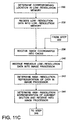
- FIGURES 11 A - 11D illustrate a flow-chart of the method for processing an image according to the present invention; and
- FIGURE 12 illustrates an alternate embodiment of components included within the computing device shown in FIGURE 5.
-
- FIGURE 5 illustrates a
system 110 for creating and processing an image from PostScript. Thesystem 110 includes acomputing device 112 to which anoutput device 120 is connected. In the preferred embodiment, theoutput device 120 is a color printing device. However it is to be understood that other output devices (e.g., a color facsimile machine) are also contemplated. FIGURE 6 illustrates components within thecomputing device 112. - Objects within the image are processed from back to front. While the preferred embodiment describes receiving the image in the PostScript language, it is to be understood that other page description languages are also contemplated.
- As described above, a description of a page contains one or more types of object: text, synthetic graphics, and pictorial. The following section describes processing of synthetic graphics.
- As the image is rasterized, successive sections (e.g., pixels of interest) of the rasterized data we received, one after another, from the
display memory 124 into theimage processor 122. As each pixel of interest is received in theimage processor 122, that segment of data is transformed into low-resolution, antialiased data. The antialiased data includes intermediate values along edges of objects within the image for providing the appearance of smoothness. - FIGURE 7 illustrates an
image 126 to be processed according to the method of the present invention. Theimage 126 includes fourobjects objects image 126 is processed one after another. Within theimage 126 shown in FIGURE 7, two (2) of theobjects edges common edge 144. The other two (2) objects 134, 136 are circles that overlap one another. Acommon edge 146 between the lower andupper circles upper circle 136. - The
first rectangle 130 and thelower circle 134 include a first color, which is illustrated by horizontal lines. Thesecond rectangle 132 and theupper circle 136 include a second color, which is illustrated by vertical lines. - The
common edge 144 between the two (2)rectangles common edge 146 between the two (2) circles 134, 136 include a plurality of pixels. It is not uncommon for one or more of the pixels along thecommon edges second rectangles upper circles common edges - FIGURE 8 illustrates an enlarged view of a pixel of
interest 150 showing thecommon edge 144 between the two (2)rectangles interest 150 is partially covered by both the first and second colors. - FIGURE 9 illustrates an enlarged view of a pixel of
interest 152 from thelower circle 134. FIGURE 10 illustrates a pixel ofinterest 154 from thecommon edge 146 between the lower andupper circles interest 152 shown in FIGURE 9 is directly below the pixel of interest shown in FIGURE 10. In other words, the pixel ofinterest 152 shown in FIGURE 9 is positioned at the same image location within theimage 126 as the pixel ofinterest 154 shown in FIGURE 10. However, the pixel ofinterest 152 shown in FIGURE 9 is rasterized earlier than the pixel ofinterest 154 shown in FIGURE 10. Therefore, the pixel ofinterest 152 is merely indicated in FIGURE 7 within parentheses. - With reference to FIGURES 5-11D, the
system 110 determines a current section of theimage 126 in astep 200. - Image coordinates of the current section within the
image 126 are determined in astep 202. Respective locations within a high-resolution cache 158 and a low-resolution memory 160, which correspond to the image coordinates, are determined insteps resolution cache 156 and low-resolution memory 160 are both included within thecomputing device 112. - The size of the low-
resolution memory 160 is at least large enough to store a low-resolution representation of theentire image 126. The size of the high-resolution cache 156 may be adjusted according to different applications. More specifically, the high-resolution cache 156 is at least large enough to store data representing a high-resolution version of a single section of theimage 126. Alternatively, the size of the high-resolution cache 156 is large enough to store enough data for a high-resolution version of theentire image 126. In the preferred embodiment, however, the high-resolution cache 156 is large enough to store high-resolution data for 1-3 rasterized scanlines of theimage 126. - Because the low-
resolution memory 160 is capable of storing an entire low-resolution version of the image, there is a one-to-one correspondence between locations within the low-resolution memory and theimage 126. In other words, x- and y-coordinates calculated in thestep 202 are preferably used to indicate a location in theimage 126 and in the low-resolution memory 160. However, because the high-resolution cache 156 is preferably much smaller than theimage 126, a hash function is used to determine locations within the high-resolution cache 156 that correspond to locations within theimage 126. - In the preferred embodiment, the hash function used to determine a location in the high-
resolution cache 156 corresponding to the image location determined in thestep 202 is 2x + 3y. Therefore, once the location of the current section (i.e., the pixel of interest) is determined within theimage 126, the x-coordinate and the y-coordinate of the image location are substituted into the hash function to determine the corresponding location within the high-resolution cache 156. - As is commonly practiced in the art, rasterization algorithms operate on objects in order from one edge to another along a scanline before proceeding to the next scanline. Thus on a given scanline, first one edge is processed. Then zero or more interior pixels are processed. Finally the other edge is processed. By the nature of the algorithm, it is clear whether an edge or interior pixel is being processed.
- For example, if the pixel of interest currently being processed is that shown in either FIGURE 8 or FIGURE 10, the pixel represents an edge of an object. If, on the other hand, the pixel of interest currently being processed is that shown in FIGURE 9, the pixel represents an interior of an object. Unlike the pixels illustrated in FIGURES 8 and 10, the pixel illustrated in FIGURE 9 only includes a single color.
- A determination is made in
step 210 as to whether the current section represents an interior or an edge of the object currently being processed. - If the pixel of interest represents an interior of the object currently being processed, low-resolution data representing the pixel of interest is received into the location, which corresponds to the current section of the
image 126, within the low-resolution memory 160, in astep 212. - Next, in a
step 214, a determination is made as to whether the location within the high-resolution cache 156, which corresponds to the current image location, includes valid data. Each "location" within the high-resolution memory includes several segments of data. More specifically, one segment contains the high-resolution data (typically sixteen bits), another segment contains the x-coordinate and the y-coordinate of the image location associated with the high-resolution data, and another segment contains a validity bit. The validity bit indicates whether the high-resolution data stored in a particular location is valid. Therefore, the determination instep 214, as to whether the data stored in the corresponding location of the high-resolution cache 156 is valid, is made by examining the validity bit. In the preferred embodiment, it is to be understood that each of the validity bits in the high-resolution cache 156 is set to "invalid" before an image is processed. - If the high-resolution data at the corresponding location is valid, the x-and y-coordinates of the high-resolution data are examined, in
step 216, to determine if they match the x- and y-coordinates of the current image location of the current section. If the coordinates in thecache 156 do match the coordinates of the current image location, the high-resolution data stored in thecache 156 corresponds to a previously rasterized layer of theimage 126. For example, the data could correspond to the portion of thelower circle 134 that is covered by theupper circle 136. Therefore, the validity bit in thecache 156 is set to "invalid" in astep 220. - If the high-resolution data at the corresponding location is invalid, and/or if the coordinates in the
cache 156 do not match the coordinates of the current image location, the validity bit is not changed. - At this point, if the pixel of interest currently being processed represents an interior of an object, processing is returned to step 200 to process the next current section, if all the sections of the
image 126 have not been processed. - If the pixel of interest represents an edge of an object currently being processed, a determination is made in
step 222 as to whether the location within the high-resolution cache 156, which corresponds to the image location of the current section, includes valid data from a previously processed section of theimage 126. - If it is determined in the
step 222 that the data already in the high-resolution cache 156 is valid,step 224 determines if the image location of the valid data in the high-resolution cache 156 corresponds to the image location of the current section. More specifically, the image location corresponding to the high-resolution data in thecache 156 is determined by examining the x-coordinate and the y-coordinate associated with the high-resolution data. Those x- and y-coordinates are then compared with the x- and y-coordinates of the current section, which were calculated instep 202. - If the image location of the high-resolution data in the high-
resolution cache 156 does not match the image location of the current section, a low-resolution representation of the high-resolution data stored in thecache 156 is determined in astep 226, and the low-resolution version of the data is received in theimage processor 122. Then, a location within the low-resolution memory 160, which corresponds to the x-and y-coordinates of the high-resolution data in the high-resolution cache 156, is ascertained in astep 230. Then, instep 232, the low-resolution representation determined instep 226 is received into the low-resolution memory location determined instep 230. Control is then passed to step 236. - If, on the other hand, the image location of the high-resolution data in the high-
resolution cache 156 does match the image location of the current section, the previous high-resolution data is received from the high-resolution cache into theimage processor 122 in astep 234. Then, control is passed to step 246. - In
step 236, the x- and y-coordinates of the image location, which correspond to the pixel of interest, are received into the corresponding location within the high-resolution cache 156. - Previous low-resolution image data, corresponding to a previously processed section at the current image location, is received from the low-
resolution memory 160 into theimage processor 122 in astep 240. A high-resolution representation of the low-resolution data, received into theimage processor 122 in thestep 236, is determined in astep 242. Then, a high-resolution representation of the low-resolution data from the current section is determined and received into theimage processor 122 in astep 244. Converting the low-resolution to high-resolution data may be done by any of a number of ways. - The two (2) high-resolution representations in the
image processor 122 are merged in astep 246. The merged data, which results fromstep 246, is then received from theimage processor 122 into the location within high-resolution cache 156, which corresponds to the image location of the current section, in astep 250. Lastly, the location within high-resolution cache 156, which corresponds to the image location of the current section, is set as "valid" in astep 252. Then, instep 254 control is returned to step 290 to process the next section. - While text and pictorials could be processed in like manner to synthetic graphics, this would be undesirably slow. Instead, pictorials are processed by writing pictorial data directly into the low-resolution frame buffer, while clearing any valid bits belonging to pixels in corresponding parts of the high resolution cache.
- In like fashion, text avoids the high resolution cache, except to clear any affected valid bits. However, while pictorials have no need for high resolution information, text is first rasterized at high resolution, then filtered down to low resolution, and stored in a low resolution character cache. Low resolution, filtered characters are then combined with the low resolution frame buffer using alpha blending. That is, the resolution character cache contains (typically 8 bit) values indicating the mask information, which is combined with the current color information and the color in the low resolution frame buffer to provide the new color which is written into the frame buffer. In those mask pixels whose value is full on, the new color is written directly to the frame buffer. In those mask pixels whose value is 0, the frame buffer is left unchanged. In the remaining mask pixels, some intermediate value, α, is used in the equation:
- A second embodiment of the computing device according to the present invention is illustrated in FIGURE 12. With reference to FIGURE 12, the
computing device 300 includes aspecialized processor 302, which provides the function of antialiasing data written into aframe buffer memory 304. Thecomputing device 300 maintains ahigh resolution cache 306 as described above for the first embodiment. Thecache 306 is maintained as some form of associative memory which can readily indicate whether a given address maps to any cache location. In this embodiment, the addresses are mapped using a hashing scheme as described above. However, other possible mapping implementations are also contemplated. - The
specialized processor 302 receives commands from ageneral processor 310 requesting thespecialized processor 302 to a) set the current color, b) set the entire low resolution pixel at some address to the current color, (i) with or (ii) without alpha blending c) set a single high resolution pixel at some address to the current color, d) set all pixels in a sub-rectangle of a high resolution block to the current color, or e) initiate a DMA copy of a block of pixels representing a pictorial, possibly rotating the block while copying. In case d), only sub-rectangles that are either (i) above and to the left, (ii) above and to the right, (iii) below and to the left, or (iv) below and to the right of a specified pixel may be specified (including a specification of which of these four cases). Thus thespecialized processor 302 recognizes at least six op-codes, all of which include operands. - The
specialized processor 302 maintains thehigh resolution cache 306, and hides from thegeneral purpose processor 310 the details of scaling low resolution pixels to high resolution form. Also, thespecialized processor 302 maintains an instruction queue, allowing thegeneral purpose processor 310 to continue with other operations without waiting for graphical operations to complete, and allowing thespecial purpose processor 302 to execute non-conflicting operations without waiting for memory reads and writes to be complete. - When the
specialized processor 302 receives a "set color" command, theprocessor 302 stores a value of the "set color" command's first operand in aninternal register 312. - When the
specialized processor 302 receives a "set low" command, thespecialized processor 302 initiates a write operation to the low resolutionframe buffer memory 304 at the destination indicated by the first and second operands, using the value in theinternal register 312. Thespecialized processor 302 also tests the high-resolution cache 306 to determine whether the destination location is in thecache 306, in which case theprocessor 302 clears the "cache valid" flag of the corresponding location. - When the
specialized processor 302 receives a "set low with alpha" command, theprocessor 302 compares the value in the third operand of the command to 0 and to all ones, and in the former case, does nothing further. In the latter case theprocessor 302 proceeds as if a regular "set low" code had been received. In the remaining cases (all other values of alpha), theprocessor 302 first initiates a read from a memory corresponding to the location in the first and second operands into aninternal register 316. Thespecialized processor 302 then combines the value in theregister 312 with the value in theregister 316, weighted by the contents of the third operand of the command. After combining the two values, the result is written back to thememory 314 at the same location. In the preferred embodiment, the combining operation applies the mathematical expression described above for alpha blending. However, other methods, including approximations using a table lookup, are also contemplated. - When the
specialized processor 302 receives a "set high resolution pixel" command it tests the high-resolution cache 306 for the location identified by the first and second operands of the command (with low order bits masked off) ― the target location. If thecache 306 contains the target location, it sets the pixel within a cache block at that location to the current color in theregister 312. If the high-resolution cache 306 does not contain the target location, it forms averages of any of the eight neighbors of the target location, which are in thecache 306. Then thespecialized processor 302 initiates reads of the remaining neighbors, along with the target location itself, from thelow resolution buffer 304. With these nine values, thespecialized processor 302 forms a scaled-up version of the target location. Thespecialized processor 302 also forms the average of the location in thecache 306 to which the target location will map after the operation, and writes that average to thelow resolution memory 304 at the location mapping to the cache location before the operation. Once the scaled-up version is available, thespecialized processor 302 replaces the location in the scaled-up version indicated by the low order bits of the first two operands with the value in theregister 312. - When the
specialized processor 302 receives a "set high resolution rectangle" command it performs essentially the same operations as for "set high resolution pixel", except that it also decodes the rectangle instructions to determine which of the high resolution pixels are to be set. Thespecialized processor 302 then sets all those pixels to the current color when it obtains a high resolution version of the location (either from the cache or by scaling). - When the
specialized processor 302 receives a "DMA write" command, theprocessor 302 sets a first register "DA" to the value of the first operand of the command: this first register is used as the starting location for the data copy. Theprocessor 302 sets a second register "DL" to the value of the second operand of the command: this is used as a scanline length during the copy. Theprocessor 302 sets a third register "DN" to the value of the third operand of the command: this is the number of scanlines in the copy; and it sets a fourth register "DS" to the value of the fourth operand of the command: this is the number of bytes between starts of successive scanlines in the input. The remaining two operands specify the X and Y location in theframe buffer 304 of the starting destination location. These remaining two operands are stored in registers DX and DY. With all registers initialized, thespecialized processor 302 begins a direct memory copy, in which it reads values at memory locations within the address space ofgeneral processor 310 specified by DA, incrementing DA and decrementing DL with every read. Thespecialized processor 302 then writes the values at X and Y locations DX and DY, incrementing DX with every write. When DN becomes zero, DX is set back to the value in the fifth operand, DY is incremented, DL is set back to the value of the third operand, DA is increased by DS-DL, and DN is decremented. When DN reaches 0, the copy ceases. - In a third embodiment, a specialized processor offers a DMA with alpha operation which combines the effects of the DMA write with the set low resolution with alpha.
Claims (3)
- A method of generating an antialiased image including at least one object, comprising:1) receiving current data describing each of the at least one objects into a processing buffer;2) rasterizing portions of the current data representing edges of the at least one objects;3) receiving the rasterized data into a high resolution cache;4) transforming the rasterized data in the high resolution cache into low resolution data; and5) receiving at least one of the current data and the rasterized data into a low resolution memory.
- The method of generating an image as set forth in claim 1, if the current section does include an edge, further including:6) determining if previous high-resolution data is included in the high-resolution cache;
if the previous high-resolution data is included in the high-resolution memory and the previous high-resolution data corresponds to a previous section of a previously processed object, the previous section having a same location within the image as the current section:7) merging the previous high-resolution data with a high-resolution version of the current data; and8) receiving the merged data from the step 7 into the high-resolution cache;
if the previous high-resolution data is included in the high-resolution cache and the previous high-resolution data corresponds to a previous section of a previously processed object, the previous section having a different location within the image as the current section:9) receiving a low-resolution version of the previous high-resolution data from the high-resolution memory into the low-resolution memory;10) receiving original low-resolution data from the low-resolution memory into the processing buffer, the original low-resolution data corresponding to the same location within the image as the current section;11) merging a high-resolution version of the original low-resolution data with the high-resolution version of the current data; and12) receiving the merged data from the step 11 into the high-resolution memory;
if the previous high-resolution data is not included in the high-resolution memory:13) receiving the high-resolution version of the current data in the high-resolution cache. - A system for processing a color image, comprising:a high-resolution cache for storing high-resolution data;a low-resolution memory, connected to the high-resolution cache, for storing low-resolution data, the low-resolution memory being capable of storing at least as much data as the high-resolution cache;an image processor, connected to both the high-resolution cache and the low-resolution memory, for receiving sequential segments of low-resolution and high resolution image data, as the image processor receives a current segment of the image data, the image processor one of 1) transmitting the current segment of image data to the low-resolution memory and 2) transmitting the high-resolution data to the high-resolution cache.
Applications Claiming Priority (2)
| Application Number | Priority Date | Filing Date | Title |
|---|---|---|---|
| US219833 | 1998-12-23 | ||
| US09/219,833 US6591020B1 (en) | 1998-12-23 | 1998-12-23 | Antialiazed high-resolution frame buffer architecture |
Publications (3)
| Publication Number | Publication Date |
|---|---|
| EP1014306A2 true EP1014306A2 (en) | 2000-06-28 |
| EP1014306A3 EP1014306A3 (en) | 2003-03-05 |
| EP1014306B1 EP1014306B1 (en) | 2005-04-06 |
Family
ID=22820970
Family Applications (1)
| Application Number | Title | Priority Date | Filing Date |
|---|---|---|---|
| EP99125218A Expired - Lifetime EP1014306B1 (en) | 1998-12-23 | 1999-12-17 | Antialiased high-resolution frame buffer architecture |
Country Status (4)
| Country | Link |
|---|---|
| US (1) | US6591020B1 (en) |
| EP (1) | EP1014306B1 (en) |
| JP (1) | JP2000198242A (en) |
| DE (1) | DE69924592T2 (en) |
Cited By (1)
| Publication number | Priority date | Publication date | Assignee | Title |
|---|---|---|---|---|
| GB2365301A (en) * | 2000-07-07 | 2002-02-13 | Hewlett Packard Co | Anti-aliasing using supersample buffer and texture mapping subsystem |
Families Citing this family (12)
| Publication number | Priority date | Publication date | Assignee | Title |
|---|---|---|---|---|
| US6809731B2 (en) * | 2002-01-08 | 2004-10-26 | Evans & Sutherland Computer Corporation | System and method for rendering high-resolution critical items |
| US7002599B2 (en) * | 2002-07-26 | 2006-02-21 | Sun Microsystems, Inc. | Method and apparatus for hardware acceleration of clipping and graphical fill in display systems |
| US20050219249A1 (en) * | 2003-12-31 | 2005-10-06 | Feng Xie | Integrating particle rendering and three-dimensional geometry rendering |
| US20080022218A1 (en) * | 2006-07-24 | 2008-01-24 | Arcsoft, Inc. | Method for cache image display |
| CN101617354A (en) | 2006-12-12 | 2009-12-30 | 埃文斯和萨瑟兰计算机公司 | Be used for calibrating the system and method for the rgb light of single modulator projector |
| US8358317B2 (en) | 2008-05-23 | 2013-01-22 | Evans & Sutherland Computer Corporation | System and method for displaying a planar image on a curved surface |
| US8702248B1 (en) | 2008-06-11 | 2014-04-22 | Evans & Sutherland Computer Corporation | Projection method for reducing interpixel gaps on a viewing surface |
| US8077378B1 (en) | 2008-11-12 | 2011-12-13 | Evans & Sutherland Computer Corporation | Calibration system and method for light modulation device |
| JP5187331B2 (en) * | 2010-03-23 | 2013-04-24 | コニカミノルタビジネステクノロジーズ株式会社 | Image processing apparatus, image processing method, and computer program |
| US9641826B1 (en) | 2011-10-06 | 2017-05-02 | Evans & Sutherland Computer Corporation | System and method for displaying distant 3-D stereo on a dome surface |
| US10410398B2 (en) * | 2015-02-20 | 2019-09-10 | Qualcomm Incorporated | Systems and methods for reducing memory bandwidth using low quality tiles |
| CN108874945B (en) * | 2018-06-04 | 2023-03-21 | 联想(北京)有限公司 | Data processing method and electronic equipment |
Family Cites Families (14)
| Publication number | Priority date | Publication date | Assignee | Title |
|---|---|---|---|---|
| US4704605A (en) * | 1984-12-17 | 1987-11-03 | Edelson Steven D | Method and apparatus for providing anti-aliased edges in pixel-mapped computer graphics |
| US5123085A (en) | 1990-03-19 | 1992-06-16 | Sun Microsystems, Inc. | Method and apparatus for rendering anti-aliased polygons |
| JPH0573662A (en) * | 1991-09-13 | 1993-03-26 | Mitsubishi Precision Co Ltd | Decision method for color in simulated view field signal generation device |
| JP2756048B2 (en) * | 1991-10-30 | 1998-05-25 | 富士通株式会社 | Color image color adjustment and image synthesis method and apparatus |
| US5333249A (en) | 1992-03-02 | 1994-07-26 | Xerox Corporation | Method for phase aligned nth bitting of graphics applications |
| US5684939A (en) | 1993-07-09 | 1997-11-04 | Silicon Graphics, Inc. | Antialiased imaging with improved pixel supersampling |
| US5600763A (en) | 1994-07-21 | 1997-02-04 | Apple Computer, Inc. | Error-bounded antialiased rendering of complex scenes |
| US5737455A (en) | 1994-12-12 | 1998-04-07 | Xerox Corporation | Antialiasing with grey masking techniques |
| JP2964931B2 (en) * | 1995-04-25 | 1999-10-18 | 富士ゼロックス株式会社 | Image processing apparatus and image forming apparatus |
| JPH08307618A (en) * | 1995-04-27 | 1996-11-22 | Canon Inc | Image recorder |
| JP3341575B2 (en) * | 1996-04-04 | 2002-11-05 | 三菱電機株式会社 | Image synthesis device |
| US5701365A (en) | 1996-06-21 | 1997-12-23 | Xerox Corporation | Subpixel character positioning with antialiasing with grey masking techniques |
| JP3449860B2 (en) * | 1996-06-28 | 2003-09-22 | 大日本スクリーン製造株式会社 | Image sharpness processing device |
| JPH10149431A (en) * | 1996-11-20 | 1998-06-02 | Hitachi Denshi Ltd | Picture processing method |
-
1998
- 1998-12-23 US US09/219,833 patent/US6591020B1/en not_active Expired - Lifetime
-
1999
- 1999-12-17 EP EP99125218A patent/EP1014306B1/en not_active Expired - Lifetime
- 1999-12-17 DE DE69924592T patent/DE69924592T2/en not_active Expired - Lifetime
- 1999-12-20 JP JP11360228A patent/JP2000198242A/en not_active Revoked
Non-Patent Citations (4)
| Title |
|---|
| LAU R W H: "An adaptive supersampling method" IMAGE ANALYSIS APPLICATIONS AND COMPUTER GRAPHICS. THIRD INTERNATIONAL COMPUTER SCIENCE CONFERENCE. ICSC 95. PROCEEDINGS, PROCEEDINGS OF 3RD INTERNATIONAL COMPUTER SCIENCE CONFERENCE IMAGE ANALYSIS APPLICATIONS AND COMPUTER GRAPHICS, HONG KONG, 11-13, pages 205-214, XP002225907 1995, Berlin, Germany, Springer-Verlag, Germany ISBN: 3-540-60697-1 * |
| LIN S ET AL: "An anti-aliasing method for parallel rendering" COMPUTER GRAPHICS INTERNATIONAL, 1998. PROCEEDINGS HANNOVER, GERMANY 22-26 JUNE 1998, LOS ALAMITOS, CA, USA,IEEE COMPUT. SOC, US, 22 June 1998 (1998-06-22), pages 228-235, XP010291522 ISBN: 0-8186-8445-3 * |
| PAINTER J ET AL: "Antialiased ray tracing by adaptive progressive refinement" SIGGRAPH '89. CONFERENCE PROCEEDINGS, BOSTON, MA, USA, 31 JULY-4 AUG. 1989, vol. 23, no. 3, pages 281-288, XP002225908 Computer Graphics, July 1989, USA ISSN: 0097-8930 * |
| WHITTED T: "IMPROVED ILLUMINATION MODEL FOR SHADED DISPLAY" COMMUNICATIONS OF THE ASSOCIATION FOR COMPUTING MACHINERY, ASSOCIATION FOR COMPUTING MACHINERY. NEW YORK, US, vol. 23, no. 6, June 1980 (1980-06), pages 343-349, XP000952928 ISSN: 0001-0782 * |
Cited By (3)
| Publication number | Priority date | Publication date | Assignee | Title |
|---|---|---|---|---|
| GB2365301A (en) * | 2000-07-07 | 2002-02-13 | Hewlett Packard Co | Anti-aliasing using supersample buffer and texture mapping subsystem |
| US6661424B1 (en) | 2000-07-07 | 2003-12-09 | Hewlett-Packard Development Company, L.P. | Anti-aliasing in a computer graphics system using a texture mapping subsystem to down-sample super-sampled images |
| GB2365301B (en) * | 2000-07-07 | 2004-10-13 | Hewlett Packard Co | Anti-aliasing in computer graphics system using supersample buffer and texture mapping subsystem |
Also Published As
| Publication number | Publication date |
|---|---|
| JP2000198242A (en) | 2000-07-18 |
| DE69924592T2 (en) | 2005-09-15 |
| EP1014306A3 (en) | 2003-03-05 |
| EP1014306B1 (en) | 2005-04-06 |
| DE69924592D1 (en) | 2005-05-12 |
| US6591020B1 (en) | 2003-07-08 |
Similar Documents
| Publication | Publication Date | Title |
|---|---|---|
| EP1272977B1 (en) | Shape processor | |
| KR100707579B1 (en) | A method and system for generating a frame of video data | |
| JP4756937B2 (en) | How to draw graphic objects | |
| EP1014306B1 (en) | Antialiased high-resolution frame buffer architecture | |
| US20050162441A1 (en) | Method and system for dynamically allocating a frame buffer for efficient anti-aliasing | |
| JPH08511638A (en) | Anti-aliasing device and method for automatic high-speed alignment of horizontal and vertical edges to target grid | |
| US5867612A (en) | Method and apparatus for the fast scaling of an image | |
| US7663642B2 (en) | Systems and methods for rendering a polygon in an image to be displayed | |
| US20060077210A1 (en) | Rasterizing stacked graphics objects from top to bottom | |
| JP2007245723A (en) | System, method and program for rendering document | |
| JP2003158632A (en) | Image processing method, and image processing apparatus and image processing system to execute the method | |
| JPH0729021A (en) | Picture output device | |
| US7221472B1 (en) | Compositing pages from page components | |
| JPH10247241A (en) | Convolution scanning line rendering | |
| JP2002007102A (en) | Printing controller and plotting controller and data processing method and storage medium | |
| JP2000076432A (en) | Image data interpolation device and method therefor, and medium having recorded image data interpolation program thereon | |
| JPH11224331A (en) | Raster image generation device and raster image generation method | |
| JPH11296670A (en) | Image data interpolation device, its method, and medium for recording image data interpolation program | |
| JP3560124B2 (en) | Image data interpolation device, image data interpolation method, and medium recording image data interpolation program | |
| JP3862460B2 (en) | Information processing method and apparatus, and storage medium | |
| JP4325339B2 (en) | Printing system, host computer and printer driver | |
| EP1306811A1 (en) | Triangle identification buffer | |
| JP3212148B2 (en) | Variable resolution printer | |
| JP2000343769A (en) | Printer control device | |
| AU2003220748A1 (en) | Scan-based Rendering of Abutting Graphical Objects |
Legal Events
| Date | Code | Title | Description |
|---|---|---|---|
| PUAI | Public reference made under article 153(3) epc to a published international application that has entered the european phase |
Free format text: ORIGINAL CODE: 0009012 |
|
| AK | Designated contracting states |
Kind code of ref document: A2 Designated state(s): AT BE CH CY DE DK ES FI FR GB GR IE IT LI LU MC NL PT SE |
|
| AX | Request for extension of the european patent |
Free format text: AL;LT;LV;MK;RO;SI |
|
| PUAL | Search report despatched |
Free format text: ORIGINAL CODE: 0009013 |
|
| RIC1 | Information provided on ipc code assigned before grant |
Ipc: 7G 06T 11/00 B Ipc: 7G 06T 15/50 A |
|
| AK | Designated contracting states |
Kind code of ref document: A3 Designated state(s): AT BE CH CY DE DK ES FI FR GB GR IE IT LI LU MC NL PT SE Designated state(s): AT BE CH CY DE DK ES FI FR GB GR IE IT LI LU MC NL PT SE |
|
| AX | Request for extension of the european patent |
Extension state: AL LT LV MK RO SI |
|
| 17P | Request for examination filed |
Effective date: 20030905 |
|
| AKX | Designation fees paid |
Designated state(s): DE FR GB |
|
| 17Q | First examination report despatched |
Effective date: 20040121 |
|
| GRAP | Despatch of communication of intention to grant a patent |
Free format text: ORIGINAL CODE: EPIDOSNIGR1 |
|
| GRAS | Grant fee paid |
Free format text: ORIGINAL CODE: EPIDOSNIGR3 |
|
| GRAA | (expected) grant |
Free format text: ORIGINAL CODE: 0009210 |
|
| AK | Designated contracting states |
Kind code of ref document: B1 Designated state(s): DE FR GB |
|
| REG | Reference to a national code |
Ref country code: GB Ref legal event code: FG4D |
|
| REG | Reference to a national code |
Ref country code: IE Ref legal event code: FG4D |
|
| REF | Corresponds to: |
Ref document number: 69924592 Country of ref document: DE Date of ref document: 20050512 Kind code of ref document: P |
|
| ET | Fr: translation filed | ||
| PLBE | No opposition filed within time limit |
Free format text: ORIGINAL CODE: 0009261 |
|
| STAA | Information on the status of an ep patent application or granted ep patent |
Free format text: STATUS: NO OPPOSITION FILED WITHIN TIME LIMIT |
|
| 26N | No opposition filed |
Effective date: 20060110 |
|
| PGFP | Annual fee paid to national office [announced via postgrant information from national office to epo] |
Ref country code: GB Payment date: 20131125 Year of fee payment: 15 Ref country code: DE Payment date: 20131121 Year of fee payment: 15 |
|
| PGFP | Annual fee paid to national office [announced via postgrant information from national office to epo] |
Ref country code: FR Payment date: 20131219 Year of fee payment: 15 |
|
| REG | Reference to a national code |
Ref country code: DE Ref legal event code: R119 Ref document number: 69924592 Country of ref document: DE |
|
| GBPC | Gb: european patent ceased through non-payment of renewal fee |
Effective date: 20141217 |
|
| REG | Reference to a national code |
Ref country code: FR Ref legal event code: ST Effective date: 20150831 |
|
| PG25 | Lapsed in a contracting state [announced via postgrant information from national office to epo] |
Ref country code: DE Free format text: LAPSE BECAUSE OF NON-PAYMENT OF DUE FEES Effective date: 20150701 Ref country code: GB Free format text: LAPSE BECAUSE OF NON-PAYMENT OF DUE FEES Effective date: 20141217 |
|
| PG25 | Lapsed in a contracting state [announced via postgrant information from national office to epo] |
Ref country code: FR Free format text: LAPSE BECAUSE OF NON-PAYMENT OF DUE FEES Effective date: 20141231 |