EP1014070A2 - Splice loss estimation based on image processing - Google Patents
Splice loss estimation based on image processing Download PDFInfo
- Publication number
- EP1014070A2 EP1014070A2 EP99850200A EP99850200A EP1014070A2 EP 1014070 A2 EP1014070 A2 EP 1014070A2 EP 99850200 A EP99850200 A EP 99850200A EP 99850200 A EP99850200 A EP 99850200A EP 1014070 A2 EP1014070 A2 EP 1014070A2
- Authority
- EP
- European Patent Office
- Prior art keywords
- deformation
- fiber
- splice
- splicing
- fibers
- Prior art date
- Legal status (The legal status is an assumption and is not a legal conclusion. Google has not performed a legal analysis and makes no representation as to the accuracy of the status listed.)
- Withdrawn
Links
- 238000012545 processing Methods 0.000 title description 5
- 239000013307 optical fiber Substances 0.000 claims abstract description 38
- 238000000034 method Methods 0.000 claims description 50
- 230000003287 optical effect Effects 0.000 claims description 21
- 238000005452 bending Methods 0.000 claims description 3
- 239000000835 fiber Substances 0.000 abstract description 147
- 238000005253 cladding Methods 0.000 abstract description 45
- 238000007526 fusion splicing Methods 0.000 abstract description 2
- 230000004927 fusion Effects 0.000 description 20
- 238000010586 diagram Methods 0.000 description 11
- VYPSYNLAJGMNEJ-UHFFFAOYSA-N Silicium dioxide Chemical compound O=[Si]=O VYPSYNLAJGMNEJ-UHFFFAOYSA-N 0.000 description 5
- 230000008878 coupling Effects 0.000 description 5
- 238000010168 coupling process Methods 0.000 description 5
- 238000005859 coupling reaction Methods 0.000 description 5
- 238000003384 imaging method Methods 0.000 description 5
- 238000010891 electric arc Methods 0.000 description 4
- 230000008569 process Effects 0.000 description 4
- 239000002019 doping agent Substances 0.000 description 3
- 238000007499 fusion processing Methods 0.000 description 3
- 238000005259 measurement Methods 0.000 description 3
- 230000001902 propagating effect Effects 0.000 description 3
- 238000004458 analytical method Methods 0.000 description 2
- 230000008859 change Effects 0.000 description 2
- 238000004891 communication Methods 0.000 description 2
- 238000011109 contamination Methods 0.000 description 2
- 230000001419 dependent effect Effects 0.000 description 2
- 238000013461 design Methods 0.000 description 2
- 238000005516 engineering process Methods 0.000 description 2
- 238000002474 experimental method Methods 0.000 description 2
- 238000007429 general method Methods 0.000 description 2
- 238000005286 illumination Methods 0.000 description 2
- 238000000253 optical time-domain reflectometry Methods 0.000 description 2
- 230000005855 radiation Effects 0.000 description 2
- 235000012239 silicon dioxide Nutrition 0.000 description 2
- 239000000377 silicon dioxide Substances 0.000 description 2
- 238000012360 testing method Methods 0.000 description 2
- 229910052691 Erbium Inorganic materials 0.000 description 1
- 238000004364 calculation method Methods 0.000 description 1
- 238000004590 computer program Methods 0.000 description 1
- 230000007547 defect Effects 0.000 description 1
- 230000000994 depressogenic effect Effects 0.000 description 1
- 238000011161 development Methods 0.000 description 1
- 239000006185 dispersion Substances 0.000 description 1
- 238000009826 distribution Methods 0.000 description 1
- 230000009977 dual effect Effects 0.000 description 1
- UYAHIZSMUZPPFV-UHFFFAOYSA-N erbium Chemical compound [Er] UYAHIZSMUZPPFV-UHFFFAOYSA-N 0.000 description 1
- 229910052732 germanium Inorganic materials 0.000 description 1
- GNPVGFCGXDBREM-UHFFFAOYSA-N germanium atom Chemical compound [Ge] GNPVGFCGXDBREM-UHFFFAOYSA-N 0.000 description 1
- 238000010438 heat treatment Methods 0.000 description 1
- 230000006872 improvement Effects 0.000 description 1
- 238000009434 installation Methods 0.000 description 1
- 230000010354 integration Effects 0.000 description 1
- 230000001788 irregular Effects 0.000 description 1
- 238000004519 manufacturing process Methods 0.000 description 1
- 239000000463 material Substances 0.000 description 1
- 238000000691 measurement method Methods 0.000 description 1
- 230000007246 mechanism Effects 0.000 description 1
- 238000012986 modification Methods 0.000 description 1
- 230000004048 modification Effects 0.000 description 1
- 239000006060 molten glass Substances 0.000 description 1
- 239000002245 particle Substances 0.000 description 1
- 238000012552 review Methods 0.000 description 1
- 238000005070 sampling Methods 0.000 description 1
- 238000004088 simulation Methods 0.000 description 1
Images



Classifications
-
- G—PHYSICS
- G01—MEASURING; TESTING
- G01M—TESTING STATIC OR DYNAMIC BALANCE OF MACHINES OR STRUCTURES; TESTING OF STRUCTURES OR APPARATUS, NOT OTHERWISE PROVIDED FOR
- G01M11/00—Testing of optical apparatus; Testing structures by optical methods not otherwise provided for
- G01M11/30—Testing of optical devices, constituted by fibre optics or optical waveguides
- G01M11/37—Testing of optical devices, constituted by fibre optics or optical waveguides in which light is projected perpendicularly to the axis of the fibre or waveguide for monitoring a section thereof
-
- G—PHYSICS
- G02—OPTICS
- G02B—OPTICAL ELEMENTS, SYSTEMS OR APPARATUS
- G02B6/00—Light guides; Structural details of arrangements comprising light guides and other optical elements, e.g. couplings
- G02B6/24—Coupling light guides
- G02B6/255—Splicing of light guides, e.g. by fusion or bonding
- G02B6/2551—Splicing of light guides, e.g. by fusion or bonding using thermal methods, e.g. fusion welding by arc discharge, laser beam, plasma torch
Definitions
- the present invention relates to a method and device for estimating losses in splices made between optical fibers, in particular in splices between optical fibers bonded to each other to form ribbon fibers.
- the mean value of the splice losses of all individual fibers in a 12-fiber ribbon can attain as low a value as 0.02 - 0.04 dB for both matched cladding fibers and depressed cladding fibers, provided that the fibers used have a very good core to cladding concentricity, such as a mean eccentricity less than 0.2 ⁇ m.
- the loss in fusioned spliced generally depends on the deformation of the fiber cores caused by the splicing operation, the shape and the degree of the deformation being dependent on the accuracy of the alignment of the fiber ends with each other as well as othe conditions in the fusion process.
- An automated single-fiber fusion splicer equipped with a digital imaging system, can align the fiber ends in both transverse and longitude directions before splicing and control the fusion process during the splicing, see W. Zheng, "Real time control of arc fusion for optical fiber splicing", IEEE J. of Lightwave Technology, Vol. 11, No. 4, pp. 548 - 553, April 1993, and W. Zheng, O. Hultén and R.
- the measurement accuracy of the fiber cladding offset is about 1.3 ⁇ m using this one-view method, see A. Ide and M. Tachikura, "Fiber misalignment measurement method using one-directionally observed image", Electronics and Communications in Japan, Part 2, Vol. 72, No. 3, pp. 81 - 90, 1989.
- two-view observing systems using one CCD-camera were developed to evaluate images of ribbon fibers in two perpendicular views, see H. Watanabe, Y. Toimoto, and K. Oda, "Fiber fusion splicer for 12-fiber ribbon", Proceedings of the SPIE, Vol. 1817, Optical communications, pp. 23 - 29, 1992.
- a simple method of evaluating fiber splices is the hot-fiber image processing technique which does not require any additional hardware more than that found in existing automatic fiber splicers but only modified image processing software. It has for several years been used for evaluating single-fiber splices. It is discussed in the cited articles for W. Zheng, W. Zheng et al. and also in W. Zheng, "Loss estimation for fusion splices of single-mode fibers.”, Proceedings of International SPIE'91 Conference, in Boston, Vol. 1580, pp. 380 - 390, Sept. 1991.
- the two captured pictures are analyzed to determine a type of deformation of the fiber ends or of the cores of the fibers and to determine, as given by the outlines or contuors in the pictures, a characteristic offset associated with the type of deformation, which was first determined.
- the determined type of deformation and the determined characteristic offset are used in calculating an estimate of the optical loss in the splice.
- An optical system used for estimating the losses in a splice between fiber ribbons using the hot fiber image method must allow that the ribbon fibers are simultaneously observed in two substantially perpendicular directions. In such a direction all the individual fibers must be seen and the optical system must allow that pictures of all fibers are focused in the same image.
- the dynamic range of the exposure time of the CCD cameras should be adjusted according to the demands of the fusion process for images of cold fibers and for images of hot fibers, the hot fibers being heated during the fusioning process.
- Such an optical system is disclosed in European patent applications 98850082.3, 98850080.7 and 98850083.1.
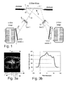
- FIG. 1 A suitable optical system as disclosed in the cited Europeans patent applications is schematically illustrated in Fig. 1.
- Two CCD cameras 1 are used to simultaneously capture images of the splice region illustrated as sections of the twelve optical fibers in an optical ribbon fiber 3.
- the splice region is by means of lenses 5 depicted on the light-sensitive surface of the cameras 1.
- the optical axes 9 of the lenses 5 are arranged in suitable angles ⁇ and ⁇ respectively to the planes of the photosensitive surfaces of the cameras 1 and the plane 11 through the object to be depicted, i.e. the plane extending through the fibers in the splice region, according to the Scheimpflug and Hinge rules, see H.M.
- loss of light power in fused splices is mainly caused by deformations of the cores as well as fiber-end contamination.
- the deformations of the cores caused by an offset of the longitudinal axes of the end portions of the spliced fibers, big cleave angles, etc. increase the coupling between the fundamental electromagnetical mode, the cladding modes and the radiation modes of light propagating in an optical fiber.
- the cleave angle is the angle of the end surface of an optical fiber in relation to the longitudinal axis of the corresponding end portion of the optical fiber, and ideally the cleave should be 90°.
- the leakage of light energy derived from the mode coupling is the splice loss.
- the splice loss can be calculated using mode coupling analysis based on the appearance of the deformation, see the article mentioned above by W. Zheng, "Loss estimation for fusion splices of single-mode fibers".
- a correct determination of the deformations of the cores from the captured digital images is a most important step in order to obtain a reasonable accuracy in splice loss estimation.
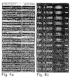
- FIG. 3a A portion of the hot image in Fig. 2c is magnified and shown in Fig. 3a. No illumination has been used in taking the image.
- the fiber was glowing since it was heated by the arc discharge during splicing.
- the thermal radiant emissivity, thus the light intensity, from different portion of the heated fiber varies with dopant materials and their concentration in silica, see T. Katagiri, M. Tachikura, and K. Ishihara, "Direct core observation method using thermal radiation of silica fiber with dopants", Electron. Commun. Japan, part 2, Vol. 71, No. 11, pp. 77 - 85, 1988.
- the Ge-doped core looks much brighter than the cladding made of pure silica.
- the light intensity profile measured at the dashed line in Fig. 3a is plotted in Fig. 3b.
- the light intensity distribution in the digital image of the heated fiber shown in Fig. 3a can be expressed as a function I ( x , z ) in the y -view projection and a function I ( y, z ) in the x -view projection respectively where the z -coordinate axis is located along the longitudinal direction of the fibers and the x - and y -coordinate axes are perpendicular thereto and to each other, the x-axis being located in the plane of the captured image in the y -view of Fig. 3a and the y -axis being located in the plane of the captured image in the x -view.
- a low-pass filter such as a Gaussian filter
- a convolution can be applied in spatial domain: where the indices m and n determine the sampling area and A and B are parameters of the Gaussian filter. The larger the values of the parameters are, the lower the pass band in the frequency domain.
- the actual values of the parameter set depend on the optical and electronic imaging system. A large number of tests are normally needed to determine an appropriate set of values for a given imaging system.
- the total splice loss ⁇ is a sum of a splice loss ⁇ x , for the x-view projection and a splice loss ⁇ y for the y -view projection, where where for both x -view and y -view projections respectively within the splice region (-L/2, L/2 ) shown in Fig. 3a.
- ⁇ g denotes the propagation constant of the guided electromagnetice LP 01 mode
- ⁇ 1 s denotes the propagation constant of a cladding mode.
- the loss as given by Eq. (4) might also have be analytic.
- Eq. (20) whatever shapes of deformation found by image processing can be directly substituted into Eq. (20) to obtain the splice loss, the calculated values being shown in Fig. 4b.
- the splice loss due to the core size deformation, the refractive index fluctuation, and contamination are not considered herein.
- the core is completely invisible in the hot image of optical fibers having a pure silica core, since there is no germanium or other dopant in the core.
- the thermal radiant emissivity of one fiber is much stronger than that of the other fiber. Then it may be very difficult to observe the cores of the two fibers at the splicing position using the same strength of fusion current.
- the loss estimation formula mentioned above would also work, if there exists some way of obtaining the core-axis deformation function without using the hot fiber images.
- fiber types commercialized for general telecommunication purposes have a very low core to cladding eccentricity, generally less than 0.2 ⁇ m.
- the core deformation due to the splicing operation can be predicted from the change of the cladding shape during the splicing process.
- a splice-image database including a large population of different fiber types and splice types, has been established including more than 200 splice data files for 12-fiber and 8-fiber ribbon of 4 main fiber types, in order to determine relations between the cladding deformation and the core deformation.
- the core deformation of all fiber types selected for the database are clearly visible in the hot images.
- Each of the splice data files contains:
- Typical relations between the core deformation and cladding deformation are summarized from these 2000 splice points in the database and are listed in the overview in Fig. 5.
- the typical cladding deformation ranges are listed in table 1 for each corresponding deformation type.
- Typical cladding deformation ranges from 1404 splice data files. The data from intentionally made bad splices are excluded. All data are absolute values except the radius offset.
- Type A Axis offset ⁇ A 1.4 ⁇ m 0.0 ⁇ m 0.4 ⁇ m 0.2 pm
- Type B Axis deform ⁇ B 13.7 ⁇ m 0.1 ⁇ m 2.3 ⁇ m 1.9 ⁇ m
- Type C Cleave angle offset ⁇ C 3.2 deg. 0.0 deg. 0.5 deg. 0.3 deg.
- Type D Axis angle offset ⁇ D 1.1 deg. 0.1 deg. 0.6 deg. 0.2 deg.
- Type E Radius offset ⁇ E 8.3 ⁇ m -4.2 ⁇ m -0.5 ⁇ m 0.01 ⁇ m
- Type F Overlap bending ⁇ F 7.0 ⁇ m 0.0 ⁇ m 1.1 ⁇ m 0.6 ⁇ m Measured loss 0.82 dB 0.00 dB 0.06 dB 0.07 dB
- the cores are deformed and/or not aligned with each other. This can in some cases be seen as a deformation of the claddings before or after the splicing operation. In other cases there is an irregular location of the outer cladding sides as seen in the pictures taken before and/or after the splicing. Also, there may be irregularities at the end surfaces of the fibers which are to be spliced. In the different cases a characteristic offset ⁇ i can be defined, which can be measured in the cold pictures taken before and/or after splicing. In the A type cladding deformation there is an offset ⁇ A of the cores of the spliced fibers.
- the offset can be measured directly as a cladding offset in the finished splice.
- a characteristic offset ⁇ B is here determined as the difference between the offset ⁇ b of the claddings before splicing and the offset ⁇ A of the claddings in the finished splice.
- the end surfaces of the fibers before splicing are not parallel - they should both be substantially perpendicular to the axes of the fibers.
- a characteristic offset ⁇ C is here defined as the angle of the end surfaces in relation to each other and is measured in the picture of the splicing region taken before actually splicing the fibers.
- ⁇ D In the type D of cladding deformations there is an angular offset ⁇ D between the cores of the fibers before splicing, which can be obtained from the angles between the outer sides of the cladding in the corresponding picture taken before splicing.
- This angular offset is the characteristic offset for this deformation type.
- the heated region after splicing has a smaller diameter than the rest of the fibers, this being called a radius offset ⁇ E which can be measured in the picture taken after splicing as the difference between the regular radius of the fibers and the radius of the narrower splice region.
- a deformation of type F there is a bending of region in which the splice is to be made. This means that in the picture taken before splicing said region is curved in one direction from the common axis of the fibers. The height of peak of this curved region in relation to the regular cladding sides is the characteristic offset ⁇ E in this case.
- r and l denote left and right
- ⁇ and ⁇ describe the magnitude of and the curvature of the core deformation respectively
- z is the position or distance in the longitudinal direction, the z -coordinate direction as defined above.
- the exponential function f e ( z ) satisfies the boundary condition of Eq. (10) when L ⁇ . Practically, if the splice is not too close to another splice or fiber end, we can always find a value of ⁇ which makes f e ( z ) to converge sufficiently fast. Different ⁇ values are actually related to different types of core deformation according to Fig. 1.
- f e ( z ) is plotted in Figs. 2a and 2b. From Figs. 2a and 2b we find that core deformation types A and B as used in Fig. 1 and table 1 can be well simulated by a function f e ( z ) having curvature magnitudes ⁇ l and ⁇ r of opposite signs, and core deformation types C to F can be simulated by a function f e ( z ) having curvature magnitudes ⁇ l and ⁇ r of the same sign.
- Figs. 3a and 3b Two examples of such superposed functions are shown in Figs. 3a and 3b.
- the functions according to Fig. 3a are suitable for simulating the deformation type F and the functions according to Fig. 3b can often be used when a splice suffers from both an axis offset and a cleave angle offset, i.e. is a combination of type B and type C.
- Figs. 8a and 8b Some typical loss coefficient curves as functions of the core deformation curvature ⁇ and the mode field radius w are plotted in Figs. 8a and 8b. From Figs. 8a and 8b it can observed that in most cases splices belonging to deformation classes C to F generate a higher splice loss than the classes A and B if the deformation magnitude ⁇ and curvature ⁇ are same. This means that the splice loss is more sensitive to a large cleave angle offset than a large axis offset. We can also see that a larger curvature ⁇ gives a lower splice loss, since a smaller portion of guided light is capable of following the curved core in order to couple to the cladding modes.
- the MFRi in current fiber types varies only from 4 ⁇ m to 5 ⁇ m and the loss coefficient can be approximated by a function which is only dependent on ⁇ i : c ( ⁇ i ) ⁇ c ( ⁇ i , ⁇
- the total splice loss will be estimated by the addition of the total losses in the x - and y -view.
- the Bellcore accuracy criteria for splice loss estimation see Bellcore, Generic Requirements for Multi-Fiber Single-Mode Optical Splices and Splicing Systems. GR-1095-CORE, Issue 2, November 1996, are widely accepted in the world and are listed in table 2. These criteria contain limits for both 90% and 100% of the population, as shown in table 2. These two limits must be satisfied in order for the criteria to be met. The criteria require a number of splices having losses larger than 0.4 dB in order to obtain conformance. The criteria are identical to those for single fiber splicing.
- the hot method did not worke very well for the True-wave fiber type, because the thin core thereof makes the resolution even worse in hot images.
- Experimental results of splice loss estimation Meet Bellcore 90% requirement Meet Bellcore 100% requirement Fiber types The hot method only Eq.(4) The cold method only Eq.(22) The combined method Eq.(23) The hot method only Eq.(4) The cold method only Eq.(22) The combined method Eq.(23) OVD-12 (40 splices) 95.96% 93.09% 93.90% 99.36% 99.80% 100.00% MCVD-12 (20 splices) 92.50% 91.20% 92.13% 99.50% 99.54% 100.00% VAD-12 (40 splices) 91.83% 88.38% 92.29% 99.35% 99.38% 99.58% Truewave-12 (20 splices) 88.17% 92.13% 92.13% 96.24% 99.54% 99.54% VAD-8 (45 splices) 93.23% 92.62% 93.23% 97.2
Landscapes
- Physics & Mathematics (AREA)
- Engineering & Computer Science (AREA)
- Plasma & Fusion (AREA)
- General Physics & Mathematics (AREA)
- Optics & Photonics (AREA)
- Chemical & Material Sciences (AREA)
- Analytical Chemistry (AREA)
- Mechanical Coupling Of Light Guides (AREA)
- Testing Of Optical Devices Or Fibers (AREA)
- Investigating Or Analysing Materials By Optical Means (AREA)
Abstract
Description
- Fig. 1 is a schematic view of an optical system according to prior art for simultaneously observing 12-fiber ribbon in two views , the system being capable of simultaneously focusing on all fibers,
- Figs. 2a - 2d are cold and hot-fiber images of a 12-fiber ribbon splice taken before the splicing operation, in the overlap step, in the very splicing step and after splicing process respectively, where Figs. 2b and 2c are taken when an electric arc is active and the hot image of Fig. 2c is taken without any background illumination,
- Fig. 3a is a hot-fiber image magnified from the 6th fiber in Fig. 2c, where the core deformation is clearly visible in the middle of the fiber,
- Fig. 3b is a light intensity profile measured at the dashed line in Fig. 3a,
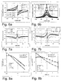
- Figs. 4a is an analyzed cold image showing the computed cladding offset, the gap between end surfaces of opposite fibers and cleave angles of the left and right fibers in one view projection,
- Fig. 4b is an analyzed hot image showing in one view projection magnified regions at the splices, the shape of the deformed cores at the splices and the splice losses, the shapes of the core deformation being derived from the image of splices and the losses being calculated from the derived core shapes,
- Fig. 5 is on overview illustrating types A - F of core deformations related to the corresponding deformation of the cladding,
- Fig. 6a is a diagram illustrating typical shapes of exponential functions fe (z) simulating core deformations of types A and B as shown in Fig. 5,
- Fig. 6b is a diagram illustrating typical shapes of exponential functions fe (z) simulating core deformations of types C, D, and E as shown in Fig. 5,
- Fig.7a is a diagram illustrating typical shapes of superposed exponential functions fe (z) simulating the core deformations of type F as shown in Fig. 5,
- Fig. 7b is a diagram illustrating typical shapes of superposed exponential functions fe (z) simulating core deformations corresponding to combinations of types B and C as shown in Fig. 5,
- Fig. 8a is a diagram illustrating the loss coefficient as a function of core deformation curvature for core deformations of types A and B and of types C, D, and E as shown in Fig. 5, where the normalized frequency V=n 1 ka(2Δ)½ is set to 2 and the refractive index of cladding is assumed to be 1.5 and the wavelength 1.3 µm,
- Fig. 8b is a diagram illustrating the loss coefficient as a function of mode field radius for core deformations of types A and B and of types C, D, and E as shown in Fig. 5, where the data of Fig. 8a are used,
- Fig. 9 is a diagram illustrating splice loss estimation for optical fibers of the OVD type, where the Bellcore requirement is met,
- Fig. 10 is a diagram illustrating splice loss estimation for optical fibers of the MCVD type, where the Bellcore requirement is met,
- Fig. 11 is a diagram illustrating splice loss estimation for optical fibers of the VAD type, where the Bellcore requirement is almost met,
- Fig. 12 is a diagram illustrating splice loss estimation for optical fibers of the True wave type, where the Bellcore requirement is not met, since the fiber has a thin core and the estimation parameters are not optimized for this specific fiber type, and
- Fig. 13 is a diagram illustrating splice loss estimation 8-fiber ribbons of the VAD type, where the Bellcore requirement is not 100% met, but very close.






- the date and time when the splice was made;
- 12 images taken before, during and after splicing for all fibers in the ribbon in both x and y view projections;
- all fusion and control parameters for making the splice, such as fusion current, fusion time, camera exposure conditions, etc.;
- all estimation parameters and estimated losses for each fiber;
- OTDR bi-directionally measured splice loss for each fiber.
| Typical cladding deformation ranges from 1404 splice data files. The data from intentionally made bad splices are excluded. All data are absolute values except the radius offset. | ||||
| Cladding deform type and measured loss | Maximum | Minimum | Average | Standard deviation |
| Type A: Axis offset δA | 1.4 µm | 0.0 µm | 0.4 µm | 0.2 pm |
| Type B: Axis deform δB | 13.7 µm | 0.1 µm | 2.3 µm | 1.9 µm |
| Type C: Cleave angle offset δC | 3.2 deg. | 0.0 deg. | 0.5 deg. | 0.3 deg. |
| Type D: Axis angle offset δD | 1.1 deg. | 0.1 deg. | 0.6 deg. | 0.2 deg. |
| Type E: Radius offset δE | 8.3 µm | -4.2 µm | -0.5 µm | 0.01 µm |
| Type F: Overlap bending δF | 7.0 µm | 0.0 µm | 1.1 µm | 0.6 µm |
| Measured loss | 0.82 dB | 0.00 dB | 0.06 dB | 0.07 dB |







From the pictures of the splice region before splicing and after splicing find the cladding shape, determine the deformation type i, i = A, B, C, D, E or F and the value of the appropriate parameter δi. (see Fig. 5)
Find the values κ i and c(γ i ) from a table-lookup in a table made .
Use Equ. (22) with w = 4 for estimating the total loss.
| Bellcore Splice Loss Estimator Accuracy Criteria | ||||
| Estimating Range | ||||
| Actual Loss | Requirement | Objective | ||
| 90% | 100% | 90% | 100% | |
| ≤0.40 dB | ±0.10 dB | ±0.25 dB | ±0.05 dB | ±0.10 dB |
| >0.40 dB | ±25% | ±50% | ±15% | ±30% |
| Experimental results of splice loss estimation | ||||||
| Meet Bellcore 90% requirement | Meet Bellcore 100% requirement | |||||
| Fiber types | The hot method only Eq.(4) | The cold method only Eq.(22) | The combined method Eq.(23) | The hot method only Eq.(4) | The cold method only Eq.(22) | The combined method Eq.(23) |
| OVD-12 (40 splices) | 95.96% | 93.09% | 93.90% | 99.36% | 99.80% | 100.00% |
| MCVD-12 (20 splices) | 92.50% | 91.20% | 92.13% | 99.50% | 99.54% | 100.00% |
| VAD-12 (40 splices) | 91.83% | 88.38% | 92.29% | 99.35% | 99.38% | 99.58% |
| Truewave-12 (20 splices) | 88.17% | 92.13% | 92.13% | 96.24% | 99.54% | 99.54% |
| VAD-8 (45 splices) | 93.23% | 92.62% | 93.23% | 97.23% | 99.08% | 99.69% |
Claims (7)
- A method of estimating loss in a splice made between two optical fibers, comprising the steps ofcharacterized intaking a picture of the splice anddetermining from the picture an estimation of the loss,that a picture is taken of a region of the optical fibers at end surfaces which are to be joined directly before splicing when the optical fibers are positioned at each other having their end surfaces in contact with each other,that a picture is taken after splicing,that the pictures are analyzed to determine a type of deformation and a characteristic offset associated with the type of deformation,that from the determined type of deformation and the determined characteristic offset an estimate of the optical loss in the splice is calculated.
- A method according to claim 1, characterized in that in determining a characteristic offset lateral offsets between exterior sides of the optical fibers are determined before and after splicing and that a difference of the lateral offsets is calculated.
- A method according to claim 1, characterized in that in determining a characteristic offset an angle between end surfaces of the optical fibers are determined before splicing.
- A method according to claim 1, characterized in that in determining a characteristic offset an angle between longitudinal directions of adjacent end regions of the optical fibers are determined before splicing.
- A method according to claim 1, characterized in that in determining a characteristic offset a difference between a radius of adjacent end regions of the optical fibers before splicing and after splicing is determined.
- A method according to claim 1, characterized in that in determining a characteristic offset a difference between a radius of adjacent end regions of the optical fibers before and after splicing is determined.
- A method according to claim 1, characterized in that in determining a characteristic offset a the height of a lateral bending of adjacent end regions of the optical fibers before splicing is determined.
Applications Claiming Priority (2)
| Application Number | Priority Date | Filing Date | Title |
|---|---|---|---|
| SE9804445 | 1998-12-18 | ||
| SE9804445A SE514476C2 (en) | 1998-12-18 | 1998-12-18 | Method for estimating loss in a joint made between two optical fibers |
Publications (2)
| Publication Number | Publication Date |
|---|---|
| EP1014070A2 true EP1014070A2 (en) | 2000-06-28 |
| EP1014070A3 EP1014070A3 (en) | 2000-07-05 |
Family
ID=20413771
Family Applications (1)
| Application Number | Title | Priority Date | Filing Date |
|---|---|---|---|
| EP99850200A Withdrawn EP1014070A3 (en) | 1998-12-18 | 1999-12-17 | Splice loss estimation based on image processing |
Country Status (4)
| Country | Link |
|---|---|
| EP (1) | EP1014070A3 (en) |
| JP (1) | JP2000193554A (en) |
| CN (1) | CN1192262C (en) |
| SE (1) | SE514476C2 (en) |
Cited By (7)
| Publication number | Priority date | Publication date | Assignee | Title |
|---|---|---|---|---|
| WO2000077550A1 (en) * | 1999-06-16 | 2000-12-21 | Scc Special Communication Cables Gmbh & Co Kg | Calculation of the attenuation of a splice according to the measurement of the dimensions |
| WO2002082137A1 (en) * | 2001-04-06 | 2002-10-17 | Telefonaktiebolaget L M Ericsson | Automatic optimization of a splice loss estimator for optical fiber splicers |
| EP1385029A1 (en) * | 2001-03-23 | 2004-01-28 | Sumitomo Electric Industries, Ltd. | Method for fusion splicing optical fibers |
| EP1273940A3 (en) * | 2001-07-02 | 2004-11-24 | The Furukawa Electric Co., Ltd. | Method for connecting optical fibers, and heat treatment apparatus used therefor |
| WO2016077054A1 (en) * | 2014-11-10 | 2016-05-19 | Panduit Corp. | Apparatus and method for terminating and testing connectors |
| EP3704462B1 (en) * | 2017-11-02 | 2022-04-06 | Panduit Corp. | Optical fiber termination method using a reference source |
| US11536849B2 (en) * | 2017-07-14 | 2022-12-27 | Neolund Ab | High resolution molecular LIDAR |
Families Citing this family (3)
| Publication number | Priority date | Publication date | Assignee | Title |
|---|---|---|---|---|
| JP6144371B1 (en) | 2016-01-14 | 2017-06-07 | 株式会社フジクラ | Intermittently connected optical fiber tape inspection method, inspection apparatus, and manufacturing method |
| CN108227077B (en) * | 2017-12-29 | 2020-03-24 | 一诺仪器(中国)有限公司 | Method and system for estimating fusion loss of ribbon fiber |
| US20240076223A1 (en) * | 2021-03-03 | 2024-03-07 | Sumitomo Electric Industries, Ltd. | Apparatus for producing glass base material, and method for producing glass base material |
Family Cites Families (1)
| Publication number | Priority date | Publication date | Assignee | Title |
|---|---|---|---|---|
| JPH0675023B2 (en) * | 1988-01-30 | 1994-09-21 | 株式会社フジクラ | Optical fiber splice loss estimation method |
-
1998
- 1998-12-18 SE SE9804445A patent/SE514476C2/en not_active IP Right Cessation
-
1999
- 1999-12-16 JP JP11376703A patent/JP2000193554A/en active Pending
- 1999-12-17 EP EP99850200A patent/EP1014070A3/en not_active Withdrawn
- 1999-12-18 CN CNB991204832A patent/CN1192262C/en not_active Expired - Fee Related
Cited By (9)
| Publication number | Priority date | Publication date | Assignee | Title |
|---|---|---|---|---|
| WO2000077550A1 (en) * | 1999-06-16 | 2000-12-21 | Scc Special Communication Cables Gmbh & Co Kg | Calculation of the attenuation of a splice according to the measurement of the dimensions |
| EP1385029A1 (en) * | 2001-03-23 | 2004-01-28 | Sumitomo Electric Industries, Ltd. | Method for fusion splicing optical fibers |
| US6835005B2 (en) | 2001-03-23 | 2004-12-28 | Sumitomo Electric Industries, Ltd. | Method for fusion splicing optical fibers |
| WO2002082137A1 (en) * | 2001-04-06 | 2002-10-17 | Telefonaktiebolaget L M Ericsson | Automatic optimization of a splice loss estimator for optical fiber splicers |
| EP1273940A3 (en) * | 2001-07-02 | 2004-11-24 | The Furukawa Electric Co., Ltd. | Method for connecting optical fibers, and heat treatment apparatus used therefor |
| WO2016077054A1 (en) * | 2014-11-10 | 2016-05-19 | Panduit Corp. | Apparatus and method for terminating and testing connectors |
| US11536849B2 (en) * | 2017-07-14 | 2022-12-27 | Neolund Ab | High resolution molecular LIDAR |
| US11768295B2 (en) | 2017-07-14 | 2023-09-26 | Beamonics Ab | High spectral resolution Scheimpflug LIDAR |
| EP3704462B1 (en) * | 2017-11-02 | 2022-04-06 | Panduit Corp. | Optical fiber termination method using a reference source |
Also Published As
| Publication number | Publication date |
|---|---|
| SE9804445L (en) | 2000-08-15 |
| EP1014070A3 (en) | 2000-07-05 |
| JP2000193554A (en) | 2000-07-14 |
| SE9804445D0 (en) | 1998-12-18 |
| CN1192262C (en) | 2005-03-09 |
| SE514476C2 (en) | 2001-02-26 |
| CN1272631A (en) | 2000-11-08 |
Similar Documents
| Publication | Publication Date | Title |
|---|---|---|
| US4945776A (en) | Method of testing spliced portion of optical fibers | |
| Zheng et al. | Erbium-doped fiber splicing and splice loss estimation | |
| JP2000193554A (en) | Splice loss evaluation based on image processing | |
| Shikama et al. | Multicore fiber connector with physical-contact connection | |
| US7245360B2 (en) | Determining MFD of optical fibers | |
| Wang et al. | Focal ratio degradation in optical fibres for the Hector integral field units | |
| US7131771B2 (en) | Automatic optimization of a splice loss estimator for optical fiber splicers | |
| Chanclou et al. | Expanded single-mode fiber using graded index multimode fiber | |
| JP3282471B2 (en) | Optical fiber fusion splicing method and apparatus | |
| Hanzawa et al. | Relationship between cross-sectional geometry and splice loss in a multicore fiber | |
| Zheng | Real time control of arc fusion for optical fiber splicing | |
| Zheng et al. | Splice-loss estimation for an automated ribbon-fiber fusion splicer | |
| Katagiri et al. | Optical microscope observation method of a single-mode optical-fiber core for precise core-axis alignment | |
| Kihara | Faults and Novel Countermeasures for Optical Fiber | |
| Pedersen et al. | Measurement and modeling of low-wavelength losses in silica fibers and their impact at communication wavelengths | |
| Zhan et al. | Bessel-beam-based side-view measurement of seven-core fibre internal core distribution | |
| Burian et al. | Minimizing Splice Loss in Hollow-Core to SMF Fusion | |
| Pashin | Research potential possibilities of estimating the basic mode transmission coefficient based on analysis overlapping of the radial distribution fields in discrete representation | |
| Kihara et al. | Novel field installable optical fiber splice and connector for optical access networks | |
| Inada et al. | Splicing of fibers by the fusion method | |
| El-Diasty | Laser-scattering-based method for investigation of ultra-low-loss arc fusion-spliced single-mode optical fibers | |
| Shao et al. | Design and Fabrication of 6-Mode 7-Core Fiber Fan-in/Fan-out Device Using Multimode Fiber | |
| Göring et al. | Optimization of integrated optic components by refractive index profile measurements | |
| Wozniak et al. | Lensed Chemically Etched Optical Fibers for Free-Space Coupling of Multicore Fibers | |
| Elechi et al. | Mitigation of Micro and Macro Bends for Improved Bandwidth in Fiber Optics Communication |
Legal Events
| Date | Code | Title | Description |
|---|---|---|---|
| PUAI | Public reference made under article 153(3) epc to a published international application that has entered the european phase |
Free format text: ORIGINAL CODE: 0009012 |
|
| PUAL | Search report despatched |
Free format text: ORIGINAL CODE: 0009013 |
|
| AK | Designated contracting states |
Kind code of ref document: A2 Designated state(s): DE FR GB IT |
|
| AX | Request for extension of the european patent |
Free format text: AL;LT;LV;MK;RO;SI |
|
| AK | Designated contracting states |
Kind code of ref document: A3 Designated state(s): AT BE CH CY DE DK ES FI FR GB GR IE IT LI LU MC NL PT SE |
|
| AX | Request for extension of the european patent |
Free format text: AL;LT;LV;MK;RO;SI |
|
| 17P | Request for examination filed |
Effective date: 20010105 |
|
| AKX | Designation fees paid |
Free format text: DE FR GB IT |
|
| RAP1 | Party data changed (applicant data changed or rights of an application transferred) |
Owner name: TELEFONAKTIEBOLAGET LM ERICSSON (PUBL) |
|
| 17Q | First examination report despatched |
Effective date: 20050321 |
|
| STAA | Information on the status of an ep patent application or granted ep patent |
Free format text: STATUS: THE APPLICATION IS DEEMED TO BE WITHDRAWN |
|
| 18D | Application deemed to be withdrawn |
Effective date: 20050802 |