EP1013975B1 - Shaft seal and turbine using the shaft seal - Google Patents
Shaft seal and turbine using the shaft seal Download PDFInfo
- Publication number
- EP1013975B1 EP1013975B1 EP99929800A EP99929800A EP1013975B1 EP 1013975 B1 EP1013975 B1 EP 1013975B1 EP 99929800 A EP99929800 A EP 99929800A EP 99929800 A EP99929800 A EP 99929800A EP 1013975 B1 EP1013975 B1 EP 1013975B1
- Authority
- EP
- European Patent Office
- Prior art keywords
- shaft
- leaves
- leaf
- seal
- rotation shaft
- Prior art date
- Legal status (The legal status is an assumption and is not a legal conclusion. Google has not performed a legal analysis and makes no representation as to the accuracy of the status listed.)
- Expired - Lifetime
Links
- 230000002093 peripheral effect Effects 0.000 claims description 35
- 239000012530 fluid Substances 0.000 claims description 33
- 238000000034 method Methods 0.000 claims description 26
- 230000001154 acute effect Effects 0.000 claims description 17
- 230000008569 process Effects 0.000 claims description 11
- 238000012545 processing Methods 0.000 claims description 9
- 230000007423 decrease Effects 0.000 claims description 8
- 230000003247 decreasing effect Effects 0.000 claims description 3
- 238000005530 etching Methods 0.000 claims description 2
- 238000003672 processing method Methods 0.000 claims description 2
- 239000007789 gas Substances 0.000 description 61
- 238000007789 sealing Methods 0.000 description 22
- 238000010586 diagram Methods 0.000 description 20
- 239000000470 constituent Substances 0.000 description 15
- 238000005299 abrasion Methods 0.000 description 12
- 239000000567 combustion gas Substances 0.000 description 10
- 238000010438 heat treatment Methods 0.000 description 8
- 230000000694 effects Effects 0.000 description 6
- 238000009826 distribution Methods 0.000 description 5
- 238000004519 manufacturing process Methods 0.000 description 5
- 238000003825 pressing Methods 0.000 description 5
- 238000000227 grinding Methods 0.000 description 4
- 239000000463 material Substances 0.000 description 4
- 230000036316 preload Effects 0.000 description 4
- 238000003466 welding Methods 0.000 description 4
- 230000001419 dependent effect Effects 0.000 description 3
- 239000000446 fuel Substances 0.000 description 3
- 238000005498 polishing Methods 0.000 description 3
- 238000005452 bending Methods 0.000 description 2
- 238000013461 design Methods 0.000 description 2
- 238000007598 dipping method Methods 0.000 description 2
- 230000006872 improvement Effects 0.000 description 2
- 230000002265 prevention Effects 0.000 description 2
- 238000005219 brazing Methods 0.000 description 1
- 239000011248 coating agent Substances 0.000 description 1
- 238000000576 coating method Methods 0.000 description 1
- 238000007796 conventional method Methods 0.000 description 1
- 238000001816 cooling Methods 0.000 description 1
- 230000008878 coupling Effects 0.000 description 1
- 238000010168 coupling process Methods 0.000 description 1
- 238000005859 coupling reaction Methods 0.000 description 1
- 238000006073 displacement reaction Methods 0.000 description 1
- 230000007613 environmental effect Effects 0.000 description 1
- 238000002474 experimental method Methods 0.000 description 1
- 229910000856 hastalloy Inorganic materials 0.000 description 1
- 229910001026 inconel Inorganic materials 0.000 description 1
- 230000007246 mechanism Effects 0.000 description 1
- 238000002156 mixing Methods 0.000 description 1
- 238000001259 photo etching Methods 0.000 description 1
- 238000007634 remodeling Methods 0.000 description 1
- 238000000926 separation method Methods 0.000 description 1
- 125000006850 spacer group Chemical group 0.000 description 1
- XLYOFNOQVPJJNP-UHFFFAOYSA-N water Substances O XLYOFNOQVPJJNP-UHFFFAOYSA-N 0.000 description 1
Images













Classifications
-
- F—MECHANICAL ENGINEERING; LIGHTING; HEATING; WEAPONS; BLASTING
- F16—ENGINEERING ELEMENTS AND UNITS; GENERAL MEASURES FOR PRODUCING AND MAINTAINING EFFECTIVE FUNCTIONING OF MACHINES OR INSTALLATIONS; THERMAL INSULATION IN GENERAL
- F16J—PISTONS; CYLINDERS; SEALINGS
- F16J15/00—Sealings
- F16J15/16—Sealings between relatively-moving surfaces
- F16J15/32—Sealings between relatively-moving surfaces with elastic sealings, e.g. O-rings
- F16J15/3284—Sealings between relatively-moving surfaces with elastic sealings, e.g. O-rings characterised by their structure; Selection of materials
- F16J15/3288—Filamentary structures, e.g. brush seals
-
- F—MECHANICAL ENGINEERING; LIGHTING; HEATING; WEAPONS; BLASTING
- F01—MACHINES OR ENGINES IN GENERAL; ENGINE PLANTS IN GENERAL; STEAM ENGINES
- F01D—NON-POSITIVE DISPLACEMENT MACHINES OR ENGINES, e.g. STEAM TURBINES
- F01D11/00—Preventing or minimising internal leakage of working-fluid, e.g. between stages
- F01D11/001—Preventing or minimising internal leakage of working-fluid, e.g. between stages for sealing space between stator blade and rotor
-
- F—MECHANICAL ENGINEERING; LIGHTING; HEATING; WEAPONS; BLASTING
- F16—ENGINEERING ELEMENTS AND UNITS; GENERAL MEASURES FOR PRODUCING AND MAINTAINING EFFECTIVE FUNCTIONING OF MACHINES OR INSTALLATIONS; THERMAL INSULATION IN GENERAL
- F16J—PISTONS; CYLINDERS; SEALINGS
- F16J15/00—Sealings
- F16J15/16—Sealings between relatively-moving surfaces
- F16J15/32—Sealings between relatively-moving surfaces with elastic sealings, e.g. O-rings
- F16J15/3284—Sealings between relatively-moving surfaces with elastic sealings, e.g. O-rings characterised by their structure; Selection of materials
- F16J15/3292—Lamellar structures
-
- F—MECHANICAL ENGINEERING; LIGHTING; HEATING; WEAPONS; BLASTING
- F05—INDEXING SCHEMES RELATING TO ENGINES OR PUMPS IN VARIOUS SUBCLASSES OF CLASSES F01-F04
- F05D—INDEXING SCHEME FOR ASPECTS RELATING TO NON-POSITIVE-DISPLACEMENT MACHINES OR ENGINES, GAS-TURBINES OR JET-PROPULSION PLANTS
- F05D2240/00—Components
- F05D2240/55—Seals
- F05D2240/56—Brush seals
-
- Y—GENERAL TAGGING OF NEW TECHNOLOGICAL DEVELOPMENTS; GENERAL TAGGING OF CROSS-SECTIONAL TECHNOLOGIES SPANNING OVER SEVERAL SECTIONS OF THE IPC; TECHNICAL SUBJECTS COVERED BY FORMER USPC CROSS-REFERENCE ART COLLECTIONS [XRACs] AND DIGESTS
- Y02—TECHNOLOGIES OR APPLICATIONS FOR MITIGATION OR ADAPTATION AGAINST CLIMATE CHANGE
- Y02T—CLIMATE CHANGE MITIGATION TECHNOLOGIES RELATED TO TRANSPORTATION
- Y02T50/00—Aeronautics or air transport
- Y02T50/60—Efficient propulsion technologies, e.g. for aircraft
Definitions
- the present invention relates to a shaft sealing structure applicable to a rotation shaft of a large fluid machine such as various kinds of turbines, compressors, water turbines or wheels, refrigerating machines, and pumps, and in particular, to a gas or steam turbine to which a shaft seal is applied.
- a typical gas turbine generates power by introducing a high-temperature and high-pressure gas into a turbine so as to expand the gas, and converting the thermal energy of the gas into mechanical rotational energy.
- a gas turbine has a seal mechanism (i.e., shaft seal), arranged between stationary blades and the rotation shaft, for reducing the leakage of the combustion gas, that is, the amount of gas which leaks from the high-pressure side to the low-pressure side.
- a non-contact labyrinth seal is widely known and used as such a sealing structure.
- the labyrinth seal When the labyrinth seal is employed, it is necessary to have a relatively large gap at the end of each fin so as to prevent the fin from contacting the face which faces the fin even if the shaft is vibrated during a transitional period of the rotation, or if the relevant portion is thermally and transitionally deformed. Therefore, the leakage is relatively large in the labyrinth seal. As a substitute for the labyrinth seal, a brush seal has been developed so as to reduce the leakage.
- Figs. 37A and 37B show a general structure of the brush seal.
- reference numeral 1 indicates a rotation shaft
- reference numeral 2 indicates a casing
- reference numeral 3 indicates a low-pressure side end plate
- reference numeral 4 indicates a high-pressure side end plate
- reference numeral 5 indicates a brazed portion
- reference numeral 6 indicates a wire bundle.
- the wire bundle 6, having a width of 1 to 3 mm, consists of filaments closely arranged with no gap between each other, and each filament has a diameter of 50 to 100 ⁇ m and suitable rigidity by which eccentricity due to vibration or thermal deformation of the rotation shaft 1 or the like can be absorbed.
- the wire bundle 6 is inclined with respect to the rotation direction so as to make an acute angle between the wire bundle and the outer-peripheral surface of the rotation shaft 1.
- the end of the wire bundle 6 contacts the outer-peripheral surface of the rotation shaft 1 via a specific pre-load, thereby reducing the leakage in the axial direction of the shaft.
- the wire bundle 6 slides on the rotation shaft 1 in contact with the shaft. This sliding motion may heat the wire bundle 6 and make the bundle red, according to the environmental conditions or the rotation speed. Therefore, the wire bundle 6 may be made of a heat-resisting material such as inconel or hastelloy according to the usage condition.
- the sliding surface that is, the outer-peripheral surface of the rotation shaft 1
- the relevant surface of the rotation shaft 1 is coated with an abrasion resistant material.
- the wire bundle 6 has smaller rigidity in the axial direction of the rotation shaft 1; thus, the inner diameter of the low-pressure side end plate is made approximately the same as the diameter of the circumference of the rotation shaft 1, thereby preventing breakage of the wire bundle 6.
- the above brush seal has the following problems.
- the rigidity of the wire bundle 6 as a constituent of the brush seal is determined according to the following capability of the wire bundle 6 with respect to the vibration of the rotation shaft 1, or to a suitable pre-load between the wire bundle 6 and the rotation shaft 1.
- the rigidity can be increased by using a thicker wire, but this has limits. That is, the maximum differential pressure for sealing in the axial direction of the rotation shaft 1, dependent on the rigidity of wire bundle 6, is approximately 5kgf/cm 2 , and a much larger differential pressure cannot be maintained using a seal.
- the diameter of each wire is approximately 50 to 100 ⁇ m, that is, very thin. Therefore, when such thin wires contact and slide on the peripheral surface of the rotation shaft 1, the wire bundle 6 may be broken and come off, and this is a serious problem when the relevant gas turbine is operated for a long time.
- the leakage around the end portion of the wire bundle 6 is much smaller than that of the labyrinth seal or the like, because the wire bundle 6 contacts the peripheral surface of the rotation shaft 1 when it slides on the surface. However, it is difficult to reliably maintain a smaller leakage between the wires of the wire bundle 6.
- the peripheral surface of the rotation shaft 1 must be coated with an abrasion resistant material because the wire bundle 6 and the peripheral surface contact each other during the sliding motion.
- a technique for making an anti-abrasion coating C which suits a rotation shaft having a large diameter and lasts for a long time has not yet been established, and the wire bundle 6 and rotation shaft 1 suffer considerable abrasion. Therefore, the brush seal has a short lifetime and must be frequently replaced.
- the present invention provides a shaft seal according to claim 1.
- a shaft seal according to claim 1.
- one side of the multi-layered leaves is fixed to a fixing member having a cylindrical shape, and the shaft seal is arranged around a predetermined shaft (mainly, a rotation shaft).
- the area fixed to the casing is larger in comparison with the conventional wires; thus, the leaves are firmly fixed to the casing, thereby preventing the leaves from falling off from the casing, as observed in the conventional brush seal.
- the top ends of the leaves have flexibility in the circumferential direction of the rotation shaft, and have high rigidity in the axial direction of the rotation shaft. Therefore, the leaves are not easily deformed in the direction of the differential pressure; and thus the permissible value of the differential pressure to be sealed can be increased.
- each leaf may be inclined with respect to the radial direction of the shaft.
- each leaf is inclined with respect to the radial direction of the shaft in a manner such that each leaf leans towards the opposite direction of the rotation direction of the rotation shaft, then the top ends of the leaves are separated from the surface of the rotation shaft due to the dynamic pressure generated by the rotation of the rotation shaft. Therefore, contact between the rotation shaft and the leaves is prevented.
- each leaf has a flat plate shape, and is inclined with respect to the peripheral surface of the rotation shaft by 30 to 45 degrees, then the flexural rigidity of the plate is small and the top ends of the leaves are separated from the surface of the rotation shaft due to the dynamic pressure generated by the rotation of the shaft. Therefore, the resistance in the rotation direction also becomes smaller, thereby reducing the sealing loss of the shaft seal.
- the gap between adjacent leaves can be substantially the same at both the inner-peripheral side and the outer-peripheral side of the ring-shaped shaft seal. In this case, it is possible to much more closely arrange the leaves, and to make the gap between the rotation shaft and the top ends of the leaves much smaller in comparison with the conventional non-contact labyrinth seal. Accordingly, it is possible to remarkably reduce the leakage of the gas, and as a result, the performance of the (gas) turbine can be improved.
- the seal diameter is sufficiently large (for example, approximately 1000 mm)
- the gaps between the leaves can be significantly the same.
- the seal diameter is relatively small, uniformly-curved leaves, which have a circular-arc shape (that is, the curvature gradually changes in the radial direction), are preferably used so as to make the widths of the gaps (between the leaves) substantially the same. Therefore, also in this case, it is possible to much more closely arrange the leaves, and the leakage through the gaps between the leaves can be reduced, thereby improving the efficiency of the turbine employing the present shaft seal.
- buoyancy providing means may be provided at the shaft-side top end of each leaf. If the shaft seal employing this structure is applied to the rotation shaft of a turbine, then during the rated operation, the top ends of the leaves are efficiently separated from the rotation shaft due to the dynamic pressure, thereby effectively preventing the contact between the rotation shaft and the leaves.
- the buoyancy providing means is a slope wherein the distance between the top point of the leaf and the peripheral surface of the rotation shaft (around which the shaft seal is arranged) gradually decreases along the rotation direction of the shaft.
- a dynamic pressure is caused by the wedge effect of the slope, so that the top ends of the leaves are separated from the rotation shaft.
- Such a slope can be formed by the following processing method comprising the steps of:
- the buoyancy providing means may be provided by forming a step in the end face of the top end of the leaf and in the axial direction of the shaft. In this case, buoyancy is generated due to the differential pressure at the step, so that the top ends of the leaves are separated from the rotation shaft.
- the buoyancy providing means may be provided by forming a step in the end face of the top end of the leaf and in the circumferential direction of the shaft. In this case, the top ends of the leaves are separated from the rotation shaft by using the dynamic pressure caused by the rotation.
- each leaf is not parallel with the axial direction of the shaft.
- the length of the passage between adjacent leaves is longer than the length of the axial direction, thereby increasing the resistance of the passage. Accordingly, the leakage between the leaves can be further reduced.
- the top ends of the leaves are separated from the shaft. Therefore, the top ends of the leaves can be separated from the rotation shaft, and the contact between the rotation shaft and the leaves can be prevented. Accordingly, it is possible to prevent excessive heating and abrasion caused by the contact of the leaves and the rotation shaft.
- circumferential end plates may be respectively arranged at both sides of the leaves, and a gap may be provided between the leaves and each end plate wherein the width of the gap is as narrow as possible for the leaves to move. Accordingly, the pressure applied to the leaves from the high-pressure side and the suction force applied to the leaves from the low-pressure side are reduced, so that deformation of the leaves towards the direction of the differential pressure can be prevented and the resistance of the passage can be increased around the leaves.
- each leaf may be inclined with respect to the radial direction of a predetermined shaft; and the gap between the shaft and the top end of one of the end plates may be the same as the gap between the shaft and the top end of the other end plate. Accordingly, the above gap can be as small as possible for the rotation shaft to rotate, and the length of each end plate in the radial direction of the rotation shaft can be approximately the same as the length of the leaves in the radial direction, thereby much further increasing the resistance of the passage around the leaves.
- the gap between one of the end plates and the leaves can be the same as the gap between the other end plate and the leaves. In this case, deformation of the leaves along the direction of the differential pressure can be much more reliably prevented.
- the outer-peripheral base end of the ring-shape leaves are attached to a circular body consisting of a plurality of separate circular-arc portions, and a division face between the separate circular-arc portions engaging each other has a step in the circumferential direction.
- the high-pressure combustion gas which reaches the junction between the separate portions cannot pass through the junction because the division face having a step blocks the gas. Therefore, it is possible to prevent the leakage of the combustion gas through the junction.
- the above engagement in the division face can reinforce the junction.
- the leaves are grouped into a plurality of unit segments, each unit segment including a predetermined number of leaves, and space is provided between adjacent unit segments.
- each unit segment including a predetermined number of leaves
- space is provided between adjacent unit segments.
- each leaf is inclined with respect to the radial direction of the rotation shaft; and a fluid delivery unit for delivering fluid around the peripheral surface of the rotation shaft to each leaf by using the centrifugal force of the shaft is provided in an area of the rotation shaft, where leaves slides.
- the fluid around the rotation shaft is delivered toward each leaf by the centrifugal force of the shaft. Therefore, according to the pressure of the fluid, the top ends of the leaves can easily separate from the shaft, and it is possible to much more reliably prevent excessive heating and abrasion due to the contact between the rotation shaft and the leaves.
- each leaf has a gap making portion which protrudes from the surface of the leaf. If the protrusion height is the same as the width of a desired gap between the leaves, micro-gaps having a specific width can be reliably provided at both the inner-peripheral side and the outer-peripheral side, only by making the leaves contact each other via the gap making portion.
- the gap making portion may be a protruding portion produced by deforming a part of the leaf. In this case, it is unnecessary to attach a separate component to the leaf; thus, the number of necessary components is not increased.
- a protruding portion can be produced by, for example, the precise pressing method.
- the gap making portion may be a coated layer formed on a part of the leaf.
- the coated layer can be produced by using, for example, the hot dipping method. Also in this case, the gap making portion can be provided on the leaf without increasing the number of necessary components.
- the coated layer is a plated layer, the thickness thereof can be determined to micrometer order, thereby precisely providing the gap (between the leaves) over the relevant circumference of the rotation shaft.
- the gap making portion is a step produced by etching a part of the leaf. That is, when a part of each leaf is etched, a step functioning as the gap making portion is formed between the etched and non-etched areas. Accordingly, the gap between the leaves can be precisely provided.
- micro-gaps having a specific width can be reliably provided at both the inner-peripheral side and the outer-peripheral side; therefore, a turbine comprising a shaft seal structure having a high sealing capability can be easily realized.
- the shaft seal may have a plurality of escape passages in the circumferential direction, wherein the escape passages are provided by making gaps between the relevant leaves have a larger width in comparison with the other gaps between the leaves.
- the escape passage is provided in some suitable leaves of the shaft seal in the circumferential direction, and is produced by removing a freely-bending portion (at the top-end side) of the target leaves (only one end of which is fixed and supported) so that in the circumferential direction, the widths of the relevant gaps (i.e., the escape passages) generated by this removing process are larger than the other gaps.
- the leaves are grouped into a plurality of unit segments, each unit segment including a predetermined number of leaves, and the leaves of each unit segment are attached to a main leaf whose thickness is larger than that of each leaf.
- a unit segment includes 50 to 100 leaves
- the main leaf comprises a leaf portion which is positioned between the segments and whose (outer-peripheral side) base end is brazed and fixed to the base-end side of the leaves, and a skirt portion integrally connected with the inner-peripheral side of the leaf portion, wherein a small gap is provided between the skirt portion and the outer-peripheral surface of the rotation shaft.
- a plurality of leaves is supported as a single block by using the main leaf, so that the rigidity of the leaves can be improved. Therefore, even when the differential pressure between the high-pressure and low-pressure sides is large, the sealing of fluid can be realized using the leaves without damage. In addition, if a torsional load acts on the leaves due to the differential pressure, damage to the leaves can be prevented because of the above-explained increase of the rigidity (according to the blocked structure), thereby improving the durability.
- the inner-peripheral side of the skirt portion of the main leaf and the outer-peripheral surface of the rotation shaft can be in a non-contact state by using the differential pressure and dynamic pressure.
- a plurality of the above-explained shaft seals are arranged around a predetermined shaft, via a spacing between each other along the axial direction of the shaft.
- the pressure of the fluid in the high-pressure chamber is gradually reduced through a plurality of stages (of each shaft seal) along the axial direction of a rotation shaft or the like, and finally reaches the pressure of the low-pressure chamber when the fluid flows out from the last-stage shaft seal. Accordingly, in comparison with a structure employing a single shaft seal, the leakage of fluid can be remarkably reduced.
- the present invention can be effectively and easily applied to sealing of a large differential pressure around a shaft having a large diameter.
- the width in the axial direction of the shaft seal closest to the high-pressure side is largest, while the width in the axial direction of the shaft seal closest to the low-pressure side is smallest.
- the pressure gradually decreases from the high-pressure side to the low-pressure side.
- the weight flow of leakage G at each stage can be defied as follows: G ⁇ P 1 2 - P 2 2 / L
- leakage G at each stage is in inverse proportion to width L in the axial direction, and in proportion to the difference of the pressures squared. Accordingly, leakage G is decreased as width L in the axial direction becomes larger.
- the above-explained shaft seal according to the present invention is preferably applied to a gas turbine in which a high-temperature and high-pressure gas is introduced into a casing, and the high-temperature and high-pressure gas is blasted against moving blades fixed to a rotation shaft which is rotatably supported in the casing, so that the thermal energy of the gas is converted into the mechanical rotational energy and power is generated, and the shaft seal is arranged so as to seal the outer-peripheral side of the rotation shaft of the gas turbine.
- the gas turbine comprises moving blades and stationary blades alternately arranged from a high-pressure stage to a low-pressure stage along the turbine shaft; and the shaft seal is arranged between the rotation shaft and one or more stationary blades.
- the shaft seal may be fixed to the top end of the stationary blade.
- the shaft seal is provided at least between the stationary blade of the most high-pressure side and the rotation shaft.
- the turbine comprises a casing, a compressor, a rotation shaft, moving blades attached to the rotation shaft, and stationary blades attached to the casing in a manner such that the stationary blades face the moving blades, wherein:
- the present invention also provides a remodeling method comprising a step of exchanging an existing shaft seal (in particular, a conventional labyrinth or brush seal) arranged around a shaft of a turbine for a shaft seal according to the present invention.
- an existing shaft seal in particular, a conventional labyrinth or brush seal
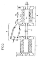
- Fig. 2 shows the general structure of the gas turbine.
- reference numeral 7 indicates a compressor
- reference numeral 8 indicates a combustor
- reference numeral 9 indicates a turbine.
- the compressor 7 draws in a large amount of air and compresses it.
- a part of the power obtained using the rotation shaft i.e., shaft 11 explained later
- the combustor 8 makes the compressed air (compressed by the compressor 7) burn by mixing the air with fuel.
- the turbine 9 draws in the combustion gas generated by the combustor 8 and makes the air expand, and blasts the expanded air against the moving blades 11a fixed to the rotation shaft 11, so as to convert the thermal energy of the combustion gas into the mechanical rotational energy and to generate the power.
- the turbine 9 In addition to the moving blades 11a at the rotation shaft 11 side, the turbine 9 also has stationary blades 12a at the casing 12 (explained later) side. These moving blades 11a and stationary blades 12a are alternately arranged in the axial direction of the rotation shaft 11. The pressure caused by the combustion gas which flows in the axial direction of the rotation shaft 11 is applied to the moving blades 11a so that the rotation shaft 11 is rotated and the rotational energy generated in the rotation shaft can be extracted from the end of the shaft and be used.
- leaf seal 10 is provided as a shaft seal (structure) for reducing the leakage of the combustion gas from the high-pressure side to the low-pressure side.
- Figs. 1A and 1B show the structure of this leaf seal.
- Fig. 1A is a perspective view showing the structure of the leaf seal
- Fig. 1B is a cross-sectional view showing a plurality of thin plates as constituents of the leaf seal.
- the above perspective view is partially broken so as to clearly show and explain the main portion of the structure, and such a partially-broken view is basically employed in the following embodiments.
- reference numeral 11 indicates a rotation shaft
- reference numeral 12 indicates a casing
- reference numeral 13 indicates a low-pressure side end plate
- reference numeral 14 indicates a high-pressure side end plate
- reference numeral 15 indicates a brazed portion
- reference numeral 18 indicates thin plates (i.e., leaves)
- reference numeral 19 indicates a gap between two adjacent leaves.
- leaf seal 10 has a structure in which plate-shape leaves 18 having a specific width in the axial direction of the rotation shaft 11 are arranged in a manner such that the leaves are multi-layered in the circumferential direction of the rotation shaft 11.
- high-pressure side end plate 14 and low-pressure side end plate 13 are respectively provided as guide plates with respect to the pressure acting direction for the high-pressure and low-pressure areas.
- the leaves 18 are designed to have a specific rigidity, dependent on the plate thickness, in the circumferential direction of the rotation shaft 11.
- the leaves 18 are fixed to casing 12 in a manner such that the leaves are inclined with respect to the rotation direction of the rotation shaft 11 so as to make an acute angle with the outer-peripheral surface of the shaft.
- each gap has substantially the same width both at the inner-peripheral top-end side and the outer-peripheral base-end side of leaves 18.
- t indicates the sum of thickness t b of leaf 18 and width t s of gap 19
- leaves 18 having a predetermined width in the axial direction of the rotation shaft 11 are multi-layered in the circumferential direction of the rotation shaft 11, and thus leaves 18 have flexibility in that circumferential direction, and have high rigidity in the axial direction of the shaft.
- the sealing component that is, leaves 18 are arranged in the axial direction of the rotation shaft 11 so that the outer-peripheral side brazed portion fixed to casing 12 is rigid in the axial direction of the rotation shaft 11. Therefore, it is possible to prevent leaves 18 from detaching from the casing 12, as observed in the conventional brush seal in which wires may detach from the casing.
- gap 19 is provided, by which the seal structure is firmly maintained during the rotation, thereby improving the durability.
- top ends of leaves 18 have high rigidity in the axial direction of the rotation shaft 11 and have flexibility in the circumferential direction of the shaft; thus, these ends are not easily deformed in the direction in which the differential pressure is applied, in comparison with the conventional brush seal. Accordingly, the present leaf seal can be used for sealing a portion having a greater differential pressure.
- each gap between the leaves is fixed both in the outer-peripheral side and the inner-peripheral side; thus, leaves 18 can be much more closely arranged and the gap between the top ends of the leaves 18 and the rotation shaft 11 can be remarkably smaller in comparison with the conventional non-contact labyrinth seal, or the like. Accordingly, the leakage of the present leaf seal can be reduced to approximately 1/3 to 1/10 as much as the leakage of the labyrinth seal, and as a result, the efficiency of (the shaft of) the gas turbine can be improved by approximately 1%.
- the above efficiency of the gas turbine is defined by "shaft output (or shaft horsepower) / fuel calorie”. Generally, the above efficiency is 38 to 40% (measured using a gas turbine employing the conventional labyrinth seal), and it is difficult to realize a higher efficiency in the conventional technique. However, when the shaft seal according to the present invention is used, the efficiency can be further improved to 39 to 41% (measured by arranging the present leaf seals at the first, second, and third-stage stationary blades).
- the efficiency can be improved by approximately 1% in comparison with the conventional type.
- the possible saving according to this improvement (of 1%) will be estimated as follows: In an example of the combined cycle power system (power output: 1,610 thousand kw), the fuel saving according to the above improvement is estimated at approximately 35 thousand tons per year.
- leaf seal 10' as shown in Fig. 3 may be employed, in which flat plate-shape leaves 18' are provided on the inner surface of casing 12. The shape of the leaves will also be described in the following embodiments.
- Figs. 4A to 4C show the structure of leaf seal 10 of the second embodiment.
- Fig. 4A is a perspective view showing the structure of the leaf seal
- Fig. 4B is a cross-sectional view showing the leaves as the constituents of the leaf seal
- Fig. 4C is a partially enlarged view for explaining a distinctive portion of Fig. 4B .
- leaves 18 of leaf seal 10 are attached to casing 12 in a manner such that angle ⁇ between the rotation direction and the peripheral surface of the rotation shaft 11 (see Fig. 4C ) is an acute angle from 30 to 45 degrees.
- each gap 19 between multi-layered leaves 18 can be regarded as substantially the same from the outer-peripheral base-end side to the inner-peripheral top-end side because the "seal" diameter, that is, the diameter of the rotation shaft 11 is sufficiently large.
- leaves 18 are brazed to the casing 12 in a manner such that angle ⁇ between the rotation direction and the peripheral surface of the rotation shaft 11 is an acute angle from 30 to 45 degrees; thus, the resistance of leaves 18 with respect to the rotation of the rotation shaft 11 is not large.
- angle ⁇ is smaller than 30°
- the top ends of leaves 18 may be too far from the surface of the rotation shaft 11 due to the dynamic pressure; thus, the sealing capability may be degraded.
- the angle ⁇ is larger than 45°, the leaves 18 may contact the rotation shaft 11 when the shaft vibrates, and thus leaves 18 may provide resistance to the rotation of the rotation shaft 11.
- the seal diameter is sufficiently large; thus, each gap 19 can be significantly the same from the outer-peripheral side to the inner-peripheral side even though flat plate-shape leaves 18 are used.
- the seal diameter is relatively small, uniformly-curved leaves 18, which have a circular-arc shape (that is, the curvature gradually changes in the radial direction), are preferably used as in the first embodiment. In this way, even if the outer diameter of the rotation shaft 11 is relatively small, the width of the gap between the leaves can be approximately fixed.
- the leaf seal 10 provided in the present gas turbine has the same basic structure as that shown in Fig. 4A of the above second embodiment, that is, the leaves 18 are attached to casing 12 in a manner such that angle ⁇ between the rotation direction and the peripheral surface of the rotation shaft 11 is a predetermined acute angle.
- each leaf 18 i.e., at the rotation shaft 11 side
- slope 2018a functioning as the buoyancy providing means of the present invention.
- the distance between the top point of the leaf and the peripheral surface 511a of the rotation shaft 11 gradually decreases along the rotation direction, and the angle ⁇ with respect to the peripheral surface 511a is very small.
- the top ends of leaves 18 are separated by receiving not only the dynamic pressure generated by the rotation of the rotation shaft 11 (because the leaves 18 are attached at an acute angle ⁇ ), but also the dynamic pressure caused by the wedge effect.
- the wedge effect is obtained because the distance between slope 2018a and peripheral surface 551a gradually decreases along the rotation direction, and thus buoyancy according to the pressure distribution 20 (see Fig. 5 ) is added. Therefore, the leaves 18 and the rotation shaft 11 are much more easily separated from each other.
- the slope 2018a is formed at the top end (i.e., the inner-peripheral side or the rotation shaft 11 side) of flat plate-shape leaf 18, and the first process is performed after the outer-peripheral base ends of leaves 18 are brazed to predetermined positions of casing 12 with a predetermined acute angle (see Fig. 6A ).
- the leaves 18 are attached at an acute angle ⁇ with respect to the peripheral surface 511a, and the top ends of the leaves 18 are processed using a discharge polishing method or a grinding method so as to form slope 2018a.
- Fig. 6B simply shows the process using the grinding method, and reference numeral 21 in the figure indicates a grindstone.
- the rotating grindstone 21 proceeds in the direction 22 indicated by the outline arrow, that is, in the same direction as the rotation direction of the rotation shaft 11, substantially in parallel with the peripheral surface 511a of the rotation shaft 11, so that the top ends of leaves 18 are ground.
- the inner-peripheral ends of leaves 18, which are free ends are pushed and held up by grindstone 21; thus, the grinding process is performed under another angle condition ⁇ ' (shifted from angle ⁇ ). Therefore, the processed slope 2018a is substantially parallel with the peripheral surface 511a while the leaves 18 are inclined by angle ⁇ '.
- the angle of inclination of the leaves 18 is shifted in advance from ⁇ to ⁇ ' and the angle ⁇ ' is maintained during the process by using a suitable tool or the like.
- Fig. 6C shows the leaves after the process, that is, the angle of inclination is returned from ⁇ ' to ⁇ by releasing the held-up state produced by using grindstone 21 (in the grinding method), or by using a tool (in the discharge polishing method).
- the slope 2018a processed with the inclination angle ⁇ ' and substantially in parallel with the peripheral surface 511a of the rotation shaft 11 has a small angle ⁇ with respect to the peripheral surface 511a, where ⁇ corresponds to the difference between angles ⁇ and ⁇ '.
- slope-forming methods it is possible to easily form slope 2018a by processing the top free ends (at the rotation shaft 11 side) of leaves 18.
- buoyancy providing means Some variations may be used as the buoyancy providing means.
- Figs. 7A and 7B show another example of the buoyancy providing means.
- the top-end face 18b (at the rotation shaft 11 side) of leaf 18 is parallel to the peripheral surface 511a, and a step 23 (height: h) is provided in the axial direction, by which the gap at the high-pressure side is larger than the gap at the low-pressure side, as shown in Fig. 7B .
- differential pressure ⁇ P as indicated by the pressure distribution 24 shown in Fig. 7B is generated between the high-pressure and low-pressure areas, and this differential pressure functions as buoyancy for separating the top ends of leaves 18.
- Figs. 8A and 8B show a further example of the buoyancy providing means.
- the top-end face 18b (at the rotation shaft 11 side) of each leaf 18 is parallel to peripheral surface 511a, and has a step 25 (height: h') in the circumferential direction, by which the gap at the front side in the rotation direction is narrower than the gap at the rear side, as shown in Fig. 8B .
- buoyancy indicated by pressure distribution 26 acts on the top ends of leaves 18 due to the dynamic pressure generated by the rotation of the rotation shaft 11.
- buoyancy acts on the leaves 18 (attached with an acute angle) in accordance with the dynamic pressure caused by the rotation of the rotation shaft 11, and the top ends also experience buoyancy, as in the case of providing slope 2018a. Accordingly, the leaves 18 experience the above buoyancy and are easily separated from the rotation shaft 11.
- the leaf seal 10 provided in the gas turbine of the present embodiment also has the same basic structure shown in Fig. 4A referred to in the above second embodiment, that is, the leaves 18 are attached to casing 12 in a manner such that the angle ⁇ between the rotation direction and the peripheral surface of the rotation shaft 11 is a predetermined acute angle.
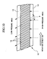
- each leaf 18 is arranged to slide with angle ⁇ with respect to line 1111 (on the peripheral surface of the rotation shaft 11) in parallel with the axis of the shaft 11.
- the top ends of leaves 18 are separated from the rotation shaft 11 when the leaves receive the pressure from the high-pressure area.
- the length of the passage between adjacent leaves 18 is longer than the length of the axial direction, thereby increasing the resistance of the passage. Accordingly, the leakage form the high-pressure side to the low-pressure side can be reduced in the leaf seal 10.
- uniformly-curved leaves 18' may be attached to the inner face of casing 12 (that is, all leaves are uniformly curved) so as to substantially fix the width of gap 19' between the leaves, as shown in Fig. 11 .
- the leaf seal 10 provided in the gas turbine of the present embodiment also has the same basic structure shown in Fig. 4A referred to in the above second embodiment, that is, the leaves 18 are attached to casing 12 in a manner such that angle a between the rotation direction and the peripheral surface of the rotation shaft 11 is a predetermined acute angle.
- Fig. 12 is a perspective view showing the structure of the shaft seal provided in the gas turbine of the present embodiment
- Fig.13 is a cross-sectional view showing the end plates and leaves surrounding the rotation shaft 11.
- low-pressure side end plate 13 and high-pressure side end plate 14 are respectively arranged at both sides of leaves 18, and along the whole circumference of the rotation shaft 11.
- the width of the gap between the leaves 18 and each end plate 13 or 14 is as narrow as possible for the leaves 18 to move, and the length of each end plate in the radial direction of the rotation shaft 11 is approximately the same as the length of the leaves in the radial direction.
- the distance between the end plate 13 and the rotation shaft 11 is the same as the distance between the end plate 14 and the rotation shaft 11, that is, at both sides of the leaves 18, the gap between the end plate and the rotation shaft 11 is the same, and has a width as narrow as possible for rotating the rotation shaft 11. Accordingly, the length of the passage generated around the leaves 18 can be increased and thus the resistance of the passage can be increased.
- the width of the gap between the leaves 18 and end plate 13 is the same as that between the leaves and end plate 14; thus, it is possible to much more reliably preventing the leaves 18 from deforming towards the direction of the differential pressure.
- the pressure applied to the leaves 18 from the high-pressure side and the suction force applied to the leaves from the low-pressure side are reduced by the low-pressure side end plate 13 and the high-pressure side end plate 14, so that the leaves 18 are not easily deformed towards the direction of the differential pressure.
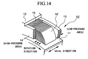
- uniformly-curved leaves 18' may be attached to the inner face of casing 12 so as to substantially fix the width of the gap between the leaves, as shown in Fig. 14 .
- Fig. 15 shows the structure of leaf seal 10 provided in the gas turbine of the present embodiment.
- the present structure comprises circular body (or member) 180, low-pressure side end plate 190, and high-pressure side end plate 200.
- the leaf seal 10 has a multi-layered structure similar to those in the above embodiments.
- high-pressure side end plate 200 is provided in the high-pressure area, while low-pressure side end plate 190 is provided in the low-pressure area.
- Each end plate functions as a guide plate with respect to the pressure acting direction, and these end plates and the circular body 180 are integrated, that is, formed as a single structural element.
- the circular body 180 is fit into groove 12a arranged in the inner surface of the casing 12 along the circumferential direction, and the top ends of leaves 18 slide on the outer-peripheral surface of the rotation shaft 11, so that the relevant space between the rotation shaft 11 and casing 12 is sealed.
- the circular body 180 consists of a plurality of separate circular-arc portions 180a, and these portions 180a are arranged along the circumferential direction on the inner surface of casing 12 so as to make a circular body.
- the high-pressure combustion gas which reaches junction 220 between the separate portions 180a and 180a cannot pass through the junction because the division face F having a step blocks the gas. Therefore, it is possible to prevent the leakage of the combustion gas through the junction.
- the above engagement in the division face can prevent the separate circular-arc portions 180a and 180a from shifting in the axial direction; thus, the circular body 180 can be reinforced.
- the shape of the division face at junction 220 may be concavoconvex as shown in Fig. 16B .
- leaf seal 10' as shown in Fig. 17 may be employed, in which flat plate-shape leaves 18' may be provided on the inner surface of casing 12.
- Fig. 18A shows the structure of leaf seal 10 provided in the gas turbine of the present embodiment
- Fig. 18B is a cross-sectional view showing the leaves 18 as constituents of the leaf seal.
- the leaves 18 are attached to casing 12 with an acute angle with respect to the peripheral surface of the rotation shaft 11.
- the leaves 18 are grouped into a plurality of unit segments, each unit segment 120 including, for example, five leaves, and space 121 is provided between adjacent unit segments 120.
- the leaves belonging to a unit segment 120 are not much affected by the leaves belonging to adjacent unit segments; thus, the leaves are much easily separated from the rotation shaft 11. Accordingly, the contact between the leaves 18 and the rotation shaft 11 can be much more reliably prevented.
- the seal diameter is sufficiently large; thus, even with flat plate-shape leaves 18, the width of each gap 9 is approximately fixed from the outer-diameter side to the inner-diameter side.
- uniformly-curved leaves 18' may be used so that the width of gap 19' between the leaves can be substantially fixed even if the outer diameter of the rotation shaft 11 is relatively small.
- the number of leaves 18 (or 18') per unit segment 120 (or 120') is not limited to five, but another number is possible and the number may be changed in the seal.
- a first type of unit segment consisting of 5 leaves and a second type of unit segment consisting of 10 leaves may be alternately arranged.
- the sizes of spaces 121 between unit segments 120 may be different depending on the design specification of the relevant shaft seal and gas turbine.
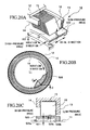
- Fig. 20A shows the structure of leaf seal 10 provided in the gas turbine of the present embodiment
- Fig. 20B is a cross-sectional view showing the leaves 18 as constituents of the leaf seal
- Fig. 20C is a cross-sectional view of face D-D of Fig. 20B .
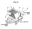
- fluid delivery unit 520 is provided in an area of the rotation shaft 11, where the leaves 18 slide.
- This unit 520 delivers fluid around the peripheral surface of the rotation shaft 11 to each leaf 18 by using the centrifugal force of the shaft.
- the unit 520 comprises ring portion 520a, arranged coaxially with the rotation shaft 11, having gap 521 between this ring portion and the peripheral surface of the shaft, and fixing portion 520b for fixing the ring portion 520a to the rotation shaft 11.
- the ring portion 520a has a plurality of (air) openings 520c which have a circular shape and are perpendicular to the axis of the rotation shaft 11.
- the top ends of leaves 18 receive a pre-load and contact the rotation shaft 11.
- the leaves 18 do not contact the rotation shaft 11 because the ends of the leaves 18 separate from the surface of the shaft due to the dynamic pressure generated by the rotation of the rotation shaft 11, and to the pressure of fluid delivered through the openings 520c of the fluid delivery unit 520.
- the fluid delivery unit 520 the fluid around the rotation shaft 11 is delivered toward each leaf 18 by the centrifugal force of the shaft. Therefore, the top ends of leaves 18 are easily separated from the shaft, and it is possible to much more reliably prevent excessive heating and abrasion.
- the seal diameter is sufficiently large; thus, even with flat plate-shape leaves 18, the width of each gap 19 is approximately fixed from the outer-diameter side to the inner-diameter side.
- uniformly-curved leaves 18' may be used so as to substantially fix the width of gap 19' between the leaves, even if the outer diameter of the rotation shaft 11 is relatively small.
- the fluid delivery unit 520 has a ring shape arranged around the rotation shaft 11; however, the shape is not limited to this, and any variation is possible if it can deliver fluid around the rotation shaft 11 to each leaf 18 (or 18') so as to make the separation of the leaves easy. For example, it is possible to provide a hole, opening, or slit opened from the peripheral surface of the rotation shaft 11 towards the inner side along the radial direction of the shaft.
- fluid in the high-pressure area is delivered via the fluid delivery unit 520; however, the unit 520 may be reversely attached so as to draw in fluid in the low-pressure area.
- the openings 520c have a circular shape; however, the shape may be an ellipse, square, or the like.
- a slit or mesh structure may also be adopted.
- the openings 520c are arranged perpendicular to the axis of the rotation shaft 11; however, this is not a limited condition, and the openings 520c may be inclined with respect to the peripheral surface of the ring portion 520a so as to much more effectively separate the top ends of leaves 18 (or 18') from the rotation shaft 11.
- a single opening 520c is provided along the axial direction of the rotation shaft 11.
- a plurality of openings having a smaller diameter may be provided so as to supply a uniform flow to the leaves 18 (or 18').
- each air opening 120c may be changed for each position so as to adjust the fluid flow.
- Fig. 22 shows the structure of leaf seal 10 provided in the gas turbine of the present embodiment.
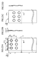
- the present embodiment has the same basic structure as that shown in Fig. 17 , that is, the shape of each leaf 18 is substantially rectangular having specific width w in the axial direction of the rotation shaft 11.
- protruding portions 18a are provided on one face (the face being perpendicular to the thickness direction) of each leaf.
- the portions 18a are made to protrude by making a concavity in the corresponding portions from the other face.
- Figs. 23A to 23D show the structure of leaf 18 shown in Fig. 22 .
- Fig. 23A is a plan view of the leaf
- Fig. 23B is a cross-sectional view along arrow B-B in Fig. 23A
- Fig. 23C is a plan view of a variation of the leaf in which the positions of the protruding portions are different from those shown in Fig. 23A
- Fig. 23D is a cross-sectional view along arrow C-C in Fig. 23C .
- the thickness t of leaf 18 is determined so that the leaf has specific rigidity in the circumferential direction of the rotation shaft 11.
- width t is 0.1 mm.
- the protrusion height h of the protruding portions 18a is suitably determined according to gap 19 (having a desired width) between leaves 18. In order to realize a high sealing capability by using leaf seal 10, it is preferable that the width of gap 19 is approximately 10 ⁇ m.
- the protrusion height h of the protruding portions 18a is 10 ⁇ m.
- Such micro protruding portions 18a can be simultaneously made by precisely pressing the leaf 18.
- the present arrangement of the protruding portions 18a has three columns along the width of leaf 18 (that is, in the axial direction of the rotation shaft 11) and two rows in the longitudinal direction.
- the protruding portions 18a are positioned in an area X defined from the base-end (i.e., outer-peripheral side) of the leaf to a position distant from the base end by a predetermined length in the longitudinal direction.
- This area X corresponds to the penetrated area in the brazing of the base end of leaf 18 to the circular body 180.
- distance s 3 from the outer-peripheral side base end to the protruding portions 18a (positioned at the outer-peripheral side) is 1 mm (see the example indicated by reference numeral 18A), or 2 mm (see the example indicated by reference numeral 18B).
- distance s 4 between the protruding portions 18a in the longitudinal direction is 2 mm.
- the width of gap 19 can be regarded as approximately the same from the outer-peripheral base-end side to the inner-peripheral top-end side because the seal diameter, that is, the diameter of the rotation shaft 11 is sufficiently large.
- a plate i.e., material
- a plate is divided into a plurality of leaves 18 having the above-described specific size by using the photo-etching method. For example, if the diameter of the rotation shaft 11 is ⁇ 350, then approximately 10,000 leaves 18 are made.
- protruding portions 18a functioning as the gap making portion are formed in each leaf 18 by using the precise pressing method, and then leaves 18 are attached to the circular body 180.
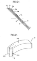
- This circular body 180 consists of a plurality of separate circular-arc portions 31 (see Fig. 25 ), and these portions 31 are combined to each other along the circumferential direction so as to make a circular body.
- the number of divided portions of the circular body 180 (i.e., the number of division) is determined dependent on the diameter of the rotation shaft 11. For example, if the diameter of the rotation shaft 11 is ⁇ 350, then the number of divisions is 2, while if the diameter of the rotation shaft 11 is ⁇ 1000, then the number of divisions is 6 (see Fig. 26 ).
- the leaves 18 are fixed to the separate circular-arc portions 31 by welding the outer-peripheral side of the leaves to the portions 31.
- a known welding method using a laser, EBW, TIG, or the like can be used.
- the shaded parts indicate penetrated areas of the welding.
- a reference surface for attaching the separate circular-arc portions 31 to the casing 12 is produced by cutting-processing the outer-peripheral surface 31A and inner-peripheral surface 31B of the separate circular-arc portions 31 (to which the leaves 18 are attached).
- the separate circular-arc portions 31 are attached to jig 32 so as to make a circular body.
- the seal diameter is obtained by subtracting 0.5 mm from the diameter of the shaft.
- the leaf seal is then attached to the gas turbine by detaching the separate circular-arc portions 31 from jig 32, and arranging them around the rotation shaft 11 and fixing the arranged portions to casing 12.
- protruding portions 18a are provided at some positions of each leaf 18 by using the precise pressing method, and the leaves 18 are made to contact with each other via these protruding portions 18a so as to make the gaps 19 between the leaves 18. Therefore, it is possible to easily and precisely make the gaps 19 on which the sealing capability depends.
- the protruding portions 18a are made by deforming some portions of each leaf 18; thus, the number of necessary constituents of the seal is not increased.
- a high sealing capability can be obtained, and the productivity can also be improved because the leaves 18 can be attached to the circular body 180 very easily. Furthermore, no strict production control is necessary, thereby reducing the manufacturing cost.
- protruding portions 18a produced using the precise pressing method are employed in each leaf 18 as the gap making portion.
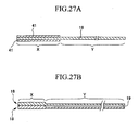
- plated layer 41 produced by using the hot dipping method, also functioning as the gap making portion is provided in a part of leaf 18.
- the penetrated area X of the welding is, for example, Cr-plated so as to form a step of plated layer 41, functioning as the gap making portion, on the surface of leaf 18.
- a plated layer 41 of a thickness of 5 ⁇ m is formed on either side (i.e., front and back) of leaf 18.
- this variation also can reliably fix the (predetermined) width of gap 19 between leaves 18 from the outer-peripheral side to the inner-peripheral side by making the leaves contact each other via plated layers 41.
- the thickness of plated layer 41 can be determined to micrometer order; thus, gaps between leaves 18 can be precisely provided over the relevant circumference of the rotation shaft 11, thereby realizing leaf seal 10 and a gas turbine employing the same, which can reliably have and maintain a high sealing capability.
- the gap making portion of the present invention is not limited to the above protruding portions 18a and plated layer 41, but a spacer integrally fixed to leaf 18 may be used, or a thick portion may be provided in the leaf 18.
- area Y (the other area than area X) in leaf 18 may be etched so as to make a step between the non-etched area X and etched area Y.
- each gap 19 between leaves 18 can be precisely provided, and the sealing capability can be much more improved.
- the shape of leaf 18 is not limited to a rectangular and flat plate shape, but a plate having a curved section like an arc may be used.
- each gap 19 between leaves 18 can be precisely fixed from the outer-peripheral base-end side to the top-end side.
- each leaf 18 has specific rigidity, determined depending on the thickness of the leaf, in the circumferential direction of the rotation shaft 11. Therefore, with rectangular leaves as shown in Fig. 22 , the corner 18b at the top end side of leaf 18 may damage the outer-peripheral surface of the rotation shaft 11, due to the relative sliding and displacement motion between the leaves 18 and the rotation shaft 11.
- arc-shaped top-end side (i.e., outer-peripheral side) edge 18c is preferably provided by chamfering the relevant corner, or by another method.
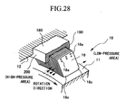
- Fig. 29 is a diagram showing the structure of a shaft seal apparatus of the present embodiment along the axis of the rotation shaft
- Fig. 30 is a diagram showing a distinctive portion (around the rotation shaft) of the gas turbine employing the above shaft seal apparatus.
- reference numeral 11 indicates a rotation shaft (i.e., rotor whose rotation axis is indicated by reference numeral 911a), and reference numeral 11a indicates moving blades attached in the outer-peripheral area of rotor disk 33 of the rotation shaft 11.
- Reference numeral 12a indicates a stationary blade. The stationary blade is provided at the previous stage of each moving blade 11a.
- shaft seals are provided at rotor end 34, inner-peripheral portions of stationary blades 12a, and the like
- reference numeral 2a indicates a support ring
- reference numeral 815 indicates a leaf seal (or a leaf-seal ring) provided between the stationary blade 12a and the rotor disk 33 inside the stationary blade
- reference numerals 815a, 815b, 815c, and 815d indicate four-stage leaf seals provided at rotor end 34.
- Reference numeral 810 indicates a high-pressure chamber at the high-pressure side of the leaf seals 815a to 815d, while reference numeral 811 indicates a low-pressure chamber.
- each leaf seal has the same basic structure as those in the previous embodiments, that is, leaves 118 are multi-layered in the circumferential direction of the rotation shaft 11.
- the leaves 118 are attached at an acute angle with respect to the rotation direction along the peripheral surface of the rotation shaft 11.
- the above leaf seal 815 is attached as follows.
- reference numeral 810 indicates a high-pressure chamber
- reference numeral 811 indicates a low-pressure chamber
- four-stage leaf seals 815a, 815b, 815c, and 815d are attached between the high-pressure chamber 810 and the low-pressure chamber 811.
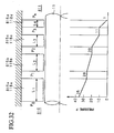
- leaves 118a, leaves 118b, leaves 118c, and leaves 118d having different widths in the axial direction are respectively attached to support ring 2a which consists of high-pressure side end plate 14, low-pressure side end plate 13, and casing 12. More specifically, the first-stage leaf seal 815a at the high-pressure chamber 810 side comprises leaves 118a having a width L 1 (in the axial direction), the second-stage leaf seal 815b comprises leaves 118b having a width L 2 , the third-stage leaf seal 815c comprises leaves 118c having a width L 3 , and the fourth-stage leaf seal 815d comprises leaves 118d having a width L 4 .
- the steps of the leaf seals (here, 815 a to 815d) and each width L 1 , L 2 , L 3 , and L 4 of leaves 18a to 18d, necessary for reducing the pressure from P 0 (in high-pressure chamber 810) to P a (in low-pressure chamber 811), can be determined.
- multi-step leaf seals are arranged and the widths (in the axial direction) of leaves 118a to 118d of each step are determined based on the formula (3) which indicates the relationship between the differential pressure (P i 2 - P i+1 2 ) of each step and weight flow of leakage G of fluid, thereby realizing a minimum leakage of fluid (i.e., gas) to the low-pressure chamber 811 side.
- leaf seals Any number of leaf seals may be used (i.e., a plurality of leaf seals are used), and the widths of each step may be the same or different (that is, the above condition L 1 >L 2 >L 3 > L 4 is not always necessary).
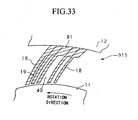
- Fig. 33 is a diagram showing the structure of a distinctive portion of leaf seal 915 of the present embodiment.
- escape passage 40 is provided in some leaves 18 (approximately 6 leaves are preferable) of leaf seal 915 in the circumferential direction. This escape passage is produced by removing a freely-bending portion of the target leaves so that in the circumferential direction, the widths of the relevant gaps (i.e., the escape passages) generated by this removing process are larger than the other gaps.
- the width of escape passage 40 is approximately 0.1 mm while the width of gaps 19 between the leaves 18 is generally 0.01 mm or the like.
- Fig. 34 is a diagram showing the structure of a distinctive portion of leaf seal 715 of the present embodiment.
- leaves 18 as the constituents of leaf seal 715 are grouped into blocks (each called a "unit segment", preferably including 50 to 100 leaves), and the leaves 18 of each block are attached to main leaf 620 whose thickness is sufficiently larger than that of the leaf 18.
- the blocks are arranged along the circumferential direction so that they are adjacent to each other.
- the main leaf 620 comprises leaf portion 620a having a front-face shape similar to that of leaf 18, and skirt portion 620b integrally connected with the inner-peripheral side of the leaf portion 620a.
- a small gap 620c is provided between the skirt portion 620b and the outer-peripheral surface of the rotation shaft 11.
- each block is brazed to a casing (not shown, and reference numeral 15 indicates a brazed portion).
- a plurality of leaves 18 is supported as a single block by using main leaf 620, so that the rigidity of leaf seal 715 can be improved. Therefore, even when the differential pressure between the high-pressure and low-pressure sides is large or when the torsional load acts on leaves 18, the sealing of fluid can be realized using the leaves without damage.
- the inner-peripheral side of the skirt portion 620b of main leaf 620 and the outer-peripheral surface of the rotation shaft 11 can be in a non-contact state.
- the shaft seal (apparatus) is generally attached to the stationary blades of the rotation shaft, but embodiments of the present invention are not limited to this arrangement.
- the shaft seal according to the present invention may be provided at the discharge portion of the compressor (i.e., leaf seal 1010), or at the intermediate shaft (i.e., leaf seal 1020).
- the rotation shaft 11 in Fig. 35 has a double-pipe structure in detail.
- the cooling steam supplied from the steam inlet 1050 to inner pipe 11C flows through the passage between the moving blades of the rotation shaft 11 and cools the moving blades, and is discharged from the outlet 1060.
- the enlarged cross-sectional view of the relevant portion is shown in Fig. 36A .
- rib 11B is a member for coupling the rotation shaft 11 and inner pipe 11C.
- the shaft seals according to the present invention are provided at positions indicated by reference numerals 1100 (here, 5 positions).
- Each shaft seal is attached as shown in Fig. 36B (an enlarged view of the area surrounded by dotted circle Q in Fig. 36A ). As shown in the figure, leaves 18 are put between the low-pressure side end plate 13 and the high-pressure side end plate 14, and are attached to casing 12.
- the gap between the rotation shaft 11 and each shaft seal is 10 to 20 ⁇ m, while in the conventional labyrinth seal, the corresponding gap is 0.5 to 1 mm. Therefore, in the leaf-type shaft seal, the leakage through the above gap is nearly zero, and most of the steam efficiently flows through each gap between the leaves, that is, as laminar flow, towards the low-pressure step side.
- the applicable gas turbine type includes a general gas turbine generating power by rotating a turbine shaft by using a combustion gas, and a gas turbine engine used in an airplane.
- the present invention can also be applied to a fluid machine using steam, such as a steam turbine.
- the distinctive features of the present invention relating to the arrangement and attaching method of the shaft seal can also be applied to the conventional brush seal using wires which are circularly arranged and attached to a circular body.
Landscapes
- Engineering & Computer Science (AREA)
- General Engineering & Computer Science (AREA)
- Mechanical Engineering (AREA)
- Sealing Devices (AREA)
- Turbine Rotor Nozzle Sealing (AREA)
- Sealing Using Fluids, Sealing Without Contact, And Removal Of Oil (AREA)
Description
- The present invention relates to a shaft sealing structure applicable to a rotation shaft of a large fluid machine such as various kinds of turbines, compressors, water turbines or wheels, refrigerating machines, and pumps, and in particular, to a gas or steam turbine to which a shaft seal is applied.
- A typical gas turbine generates power by introducing a high-temperature and high-pressure gas into a turbine so as to expand the gas, and converting the thermal energy of the gas into mechanical rotational energy. Such a gas turbine has a seal mechanism (i.e., shaft seal), arranged between stationary blades and the rotation shaft, for reducing the leakage of the combustion gas, that is, the amount of gas which leaks from the high-pressure side to the low-pressure side. Conventionally, a non-contact labyrinth seal is widely known and used as such a sealing structure. When the labyrinth seal is employed, it is necessary to have a relatively large gap at the end of each fin so as to prevent the fin from contacting the face which faces the fin even if the shaft is vibrated during a transitional period of the rotation, or if the relevant portion is thermally and transitionally deformed. Therefore, the leakage is relatively large in the labyrinth seal. As a substitute for the labyrinth seal, a brush seal has been developed so as to reduce the leakage.
-
Figs. 37A and 37B show a general structure of the brush seal. In the figures,reference numeral 1 indicates a rotation shaft,reference numeral 2 indicates a casing,reference numeral 3 indicates a low-pressure side end plate,reference numeral 4 indicates a high-pressure side end plate,reference numeral 5 indicates a brazed portion, andreference numeral 6 indicates a wire bundle. Thewire bundle 6, having a width of 1 to 3 mm, consists of filaments closely arranged with no gap between each other, and each filament has a diameter of 50 to 100 µm and suitable rigidity by which eccentricity due to vibration or thermal deformation of therotation shaft 1 or the like can be absorbed. In addition, thewire bundle 6 is inclined with respect to the rotation direction so as to make an acute angle between the wire bundle and the outer-peripheral surface of therotation shaft 1. The end of thewire bundle 6 contacts the outer-peripheral surface of therotation shaft 1 via a specific pre-load, thereby reducing the leakage in the axial direction of the shaft. - The
wire bundle 6 slides on therotation shaft 1 in contact with the shaft. This sliding motion may heat thewire bundle 6 and make the bundle red, according to the environmental conditions or the rotation speed. Therefore, thewire bundle 6 may be made of a heat-resisting material such as inconel or hastelloy according to the usage condition. In addition, the sliding surface, that is, the outer-peripheral surface of therotation shaft 1, is also subject to abrasion, as in thewire bundle 6; thus, the relevant surface of therotation shaft 1 is coated with an abrasion resistant material. Furthermore, thewire bundle 6 has smaller rigidity in the axial direction of therotation shaft 1; thus, the inner diameter of the low-pressure side end plate is made approximately the same as the diameter of the circumference of therotation shaft 1, thereby preventing breakage of thewire bundle 6. - The above brush seal has the following problems.
- In the brush seal, leakage through gaps between the wires of the
bundle 6 or gaps near the end of the bundle, or around the sliding portion (i.e., face) contacting the outer-peripheral surface of therotation shaft 1 is a typical problem. If the differential pressure of the seal exceeds a permissible value which is determined based on the diameter of each wire ofbundle 6, the structure or arrangement of the low-pressure side end plate, and the like, thewire bundle 6 is deformed towards the low-pressure side, so that the area between thewire bundle 6 and therotation shaft 1 is not sealed and thus the sealing effect cannot be obtained. - The rigidity of the
wire bundle 6 as a constituent of the brush seal is determined according to the following capability of thewire bundle 6 with respect to the vibration of therotation shaft 1, or to a suitable pre-load between thewire bundle 6 and therotation shaft 1. The rigidity can be increased by using a thicker wire, but this has limits. That is, the maximum differential pressure for sealing in the axial direction of therotation shaft 1, dependent on the rigidity ofwire bundle 6, is approximately 5kgf/cm2, and a much larger differential pressure cannot be maintained using a seal. Generally, the diameter of each wire is approximately 50 to 100 µm, that is, very thin. Therefore, when such thin wires contact and slide on the peripheral surface of therotation shaft 1, thewire bundle 6 may be broken and come off, and this is a serious problem when the relevant gas turbine is operated for a long time. - The leakage around the end portion of the
wire bundle 6 is much smaller than that of the labyrinth seal or the like, because thewire bundle 6 contacts the peripheral surface of therotation shaft 1 when it slides on the surface. However, it is difficult to reliably maintain a smaller leakage between the wires of thewire bundle 6. - In addition, the peripheral surface of the
rotation shaft 1 must be coated with an abrasion resistant material because thewire bundle 6 and the peripheral surface contact each other during the sliding motion. However, a technique for making an anti-abrasion coating C which suits a rotation shaft having a large diameter and lasts for a long time has not yet been established, and thewire bundle 6 androtation shaft 1 suffer considerable abrasion. Therefore, the brush seal has a short lifetime and must be frequently replaced. - Document
EP-A-O 391676 claim 1. - It is an object of the present invention to provide a shaft seal which has a high sealing capability and by which leakage can be reduced. Another object of the present invention is to provide a turbine using the above shaft seal, in particular, a gas turbine which has a high abrasion resistance in the seal structure, and can reduce the gas leakage from the high-pressure side to the low-pressure side.
- Therefore, the present invention provides a shaft seal according to
claim 1. Typically, one side of the multi-layered leaves is fixed to a fixing member having a cylindrical shape, and the shaft seal is arranged around a predetermined shaft (mainly, a rotation shaft). - According to the leaves employed as a sealing component, the area fixed to the casing is larger in comparison with the conventional wires; thus, the leaves are firmly fixed to the casing, thereby preventing the leaves from falling off from the casing, as observed in the conventional brush seal.
- In addition, the top ends of the leaves have flexibility in the circumferential direction of the rotation shaft, and have high rigidity in the axial direction of the rotation shaft. Therefore, the leaves are not easily deformed in the direction of the differential pressure; and thus the permissible value of the differential pressure to be sealed can be increased.
- When the vibration of the rotation shaft is large near the resonance point or the like, the leaves are deformed and the contact state with the rotation shaft is eased. In addition, under the rated conditions, the ends of the leaves separate from the surface of the shaft due to the dynamic pressure generated by the rotation of the rotation shaft. Therefore, it is possible to prevent excessive heating and abrasion caused by the contact of the leaves and the rotation shaft. Furthermore, according to the prevention of the heating due to the contact between the leaves and the rotation shaft, vibration generated depending on the thermal balance in the rotation shaft can also be prevented.
- In the above structure, each leaf may be inclined with respect to the radial direction of the shaft. In particular, if each leaf is inclined with respect to the radial direction of the shaft in a manner such that each leaf leans towards the opposite direction of the rotation direction of the rotation shaft, then the top ends of the leaves are separated from the surface of the rotation shaft due to the dynamic pressure generated by the rotation of the rotation shaft. Therefore, contact between the rotation shaft and the leaves is prevented.
- In this case, if each leaf has a flat plate shape, and is inclined with respect to the peripheral surface of the rotation shaft by 30 to 45 degrees, then the flexural rigidity of the plate is small and the top ends of the leaves are separated from the surface of the rotation shaft due to the dynamic pressure generated by the rotation of the shaft. Therefore, the resistance in the rotation direction also becomes smaller, thereby reducing the sealing loss of the shaft seal.
- The gap between adjacent leaves can be substantially the same at both the inner-peripheral side and the outer-peripheral side of the ring-shaped shaft seal. In this case, it is possible to much more closely arrange the leaves, and to make the gap between the rotation shaft and the top ends of the leaves much smaller in comparison with the conventional non-contact labyrinth seal. Accordingly, it is possible to remarkably reduce the leakage of the gas, and as a result, the performance of the (gas) turbine can be improved.
- Here, if the seal diameter is sufficiently large (for example, approximately 1000 mm), then the gaps between the leaves can be significantly the same. However, if the seal diameter is relatively small, uniformly-curved leaves, which have a circular-arc shape (that is, the curvature gradually changes in the radial direction), are preferably used so as to make the widths of the gaps (between the leaves) substantially the same. Therefore, also in this case, it is possible to much more closely arrange the leaves, and the leakage through the gaps between the leaves can be reduced, thereby improving the efficiency of the turbine employing the present shaft seal.
- Also in the shaft seal of the present invention, buoyancy providing means may be provided at the shaft-side top end of each leaf. If the shaft seal employing this structure is applied to the rotation shaft of a turbine, then during the rated operation, the top ends of the leaves are efficiently separated from the rotation shaft due to the dynamic pressure, thereby effectively preventing the contact between the rotation shaft and the leaves.
- As a preferable example, the buoyancy providing means is a slope wherein the distance between the top point of the leaf and the peripheral surface of the rotation shaft (around which the shaft seal is arranged) gradually decreases along the rotation direction of the shaft. In this case, a dynamic pressure is caused by the wedge effect of the slope, so that the top ends of the leaves are separated from the rotation shaft.
- Such a slope can be formed by the following processing method comprising the steps of:
- (1) fixing the outer-peripheral base ends of the leaves in a manner such that each leaf is inclined with respect to the radial direction of the shaft and that each leaf leans towards the opposite direction of the rotation direction of the rotation shaft;
- (2) pushing the inner-peripheral free ends of each leaf in a manner such that the acute angle between the leaf and the peripheral surface of the rotation shaft is decreased; and processing the top end of the leaf under the above pushed state, so as to make the top end substantially in parallel with the rotation shaft; and
- (3) releasing the pushed state after the processing process.
- As another example, the buoyancy providing means may be provided by forming a step in the end face of the top end of the leaf and in the axial direction of the shaft. In this case, buoyancy is generated due to the differential pressure at the step, so that the top ends of the leaves are separated from the rotation shaft.
- As a further example, the buoyancy providing means may be provided by forming a step in the end face of the top end of the leaf and in the circumferential direction of the shaft. In this case, the top ends of the leaves are separated from the rotation shaft by using the dynamic pressure caused by the rotation.
- It is possible that the direction of the width of each leaf is not parallel with the axial direction of the shaft. In this case, the length of the passage between adjacent leaves is longer than the length of the axial direction, thereby increasing the resistance of the passage. Accordingly, the leakage between the leaves can be further reduced.
- Typically, when the leaves receive pressure from the high-pressure side, the top ends of the leaves are separated from the shaft. Therefore, the top ends of the leaves can be separated from the rotation shaft, and the contact between the rotation shaft and the leaves can be prevented. Accordingly, it is possible to prevent excessive heating and abrasion caused by the contact of the leaves and the rotation shaft.
- Also in the shaft seal of the present invention, circumferential end plates may be respectively arranged at both sides of the leaves, and a gap may be provided between the leaves and each end plate wherein the width of the gap is as narrow as possible for the leaves to move. Accordingly, the pressure applied to the leaves from the high-pressure side and the suction force applied to the leaves from the low-pressure side are reduced, so that deformation of the leaves towards the direction of the differential pressure can be prevented and the resistance of the passage can be increased around the leaves.
- Here, each leaf may be inclined with respect to the radial direction of a predetermined shaft; and the gap between the shaft and the top end of one of the end plates may be the same as the gap between the shaft and the top end of the other end plate. Accordingly, the above gap can be as small as possible for the rotation shaft to rotate, and the length of each end plate in the radial direction of the rotation shaft can be approximately the same as the length of the leaves in the radial direction, thereby much further increasing the resistance of the passage around the leaves.
- In addition, the gap between one of the end plates and the leaves can be the same as the gap between the other end plate and the leaves. In this case, deformation of the leaves along the direction of the differential pressure can be much more reliably prevented.
- In a variation, the outer-peripheral base end of the ring-shape leaves are attached to a circular body consisting of a plurality of separate circular-arc portions, and a division face between the separate circular-arc portions engaging each other has a step in the circumferential direction. According to this structure, the high-pressure combustion gas which reaches the junction between the separate portions cannot pass through the junction because the division face having a step blocks the gas. Therefore, it is possible to prevent the leakage of the combustion gas through the junction. In addition, the above engagement in the division face can reinforce the junction.
- In another variation, the leaves are grouped into a plurality of unit segments, each unit segment including a predetermined number of leaves, and space is provided between adjacent unit segments. In this case, when the top ends of the
leaves 18 separate from a contact surface, the leaves belonging to a unit segment are not much affected by the leaves belonging to adjacent unit segments because there is a space between the unit segments. Therefore, the leaves can much more easily separate from a contact surface, typically, from a rotation shaft. - It is also possible that each leaf is inclined with respect to the radial direction of the rotation shaft; and a fluid delivery unit for delivering fluid around the peripheral surface of the rotation shaft to each leaf by using the centrifugal force of the shaft is provided in an area of the rotation shaft, where leaves slides. According to this structure, the fluid around the rotation shaft is delivered toward each leaf by the centrifugal force of the shaft. Therefore, according to the pressure of the fluid, the top ends of the leaves can easily separate from the shaft, and it is possible to much more reliably prevent excessive heating and abrasion due to the contact between the rotation shaft and the leaves.
- In another variation, each leaf has a gap making portion which protrudes from the surface of the leaf. If the protrusion height is the same as the width of a desired gap between the leaves, micro-gaps having a specific width can be reliably provided at both the inner-peripheral side and the outer-peripheral side, only by making the leaves contact each other via the gap making portion.
- The gap making portion may be a protruding portion produced by deforming a part of the leaf. In this case, it is unnecessary to attach a separate component to the leaf; thus, the number of necessary components is not increased. Such a protruding portion can be produced by, for example, the precise pressing method.
- The gap making portion may be a coated layer formed on a part of the leaf. The coated layer can be produced by using, for example, the hot dipping method. Also in this case, the gap making portion can be provided on the leaf without increasing the number of necessary components. In particular, if the coated layer is a plated layer, the thickness thereof can be determined to micrometer order, thereby precisely providing the gap (between the leaves) over the relevant circumference of the rotation shaft.
- When the number of necessary components is not increased as described above, the productivity can be improved and no strict production control is necessary, thereby reducing the manufacturing cost.
- In a further variation, the gap making portion is a step produced by etching a part of the leaf. That is, when a part of each leaf is etched, a step functioning as the gap making portion is formed between the etched and non-etched areas. Accordingly, the gap between the leaves can be precisely provided.
- That is, only by making the leaves contact each other via the gap making portion, micro-gaps having a specific width can be reliably provided at both the inner-peripheral side and the outer-peripheral side; therefore, a turbine comprising a shaft seal structure having a high sealing capability can be easily realized.
- The shaft seal may have a plurality of escape passages in the circumferential direction, wherein the escape passages are provided by making gaps between the relevant leaves have a larger width in comparison with the other gaps between the leaves.
- Preferably, the escape passage is provided in some suitable leaves of the shaft seal in the circumferential direction, and is produced by removing a freely-bending portion (at the top-end side) of the target leaves (only one end of which is fixed and supported) so that in the circumferential direction, the widths of the relevant gaps (i.e., the escape passages) generated by this removing process are larger than the other gaps.
- According to the above structure, a part of the pressure of the high-pressure side of the shaft seal is released to the low-pressure side through the escape passages provided along the circumferential direction of the shaft seal. Therefore, an increase of the differential pressure between the high-pressure and low-pressure sides is prevented and thus damage to the leaves due to the increase of the differential pressure can be prevented. Accordingly, even when the leaves having a smaller rigidity are used so as to improve the fluid sealing capability, no damage occurs because the above pressure-releasing function using the escape passages is effective.
- It is also possible that the leaves are grouped into a plurality of unit segments, each unit segment including a predetermined number of leaves, and the leaves of each unit segment are attached to a main leaf whose thickness is larger than that of each leaf.
- In a preferable example, a unit segment includes 50 to 100 leaves, and the main leaf comprises a leaf portion which is positioned between the segments and whose (outer-peripheral side) base end is brazed and fixed to the base-end side of the leaves, and a skirt portion integrally connected with the inner-peripheral side of the leaf portion, wherein a small gap is provided between the skirt portion and the outer-peripheral surface of the rotation shaft.
- According to this structure, a plurality of leaves is supported as a single block by using the main leaf, so that the rigidity of the leaves can be improved. Therefore, even when the differential pressure between the high-pressure and low-pressure sides is large, the sealing of fluid can be realized using the leaves without damage. In addition, if a torsional load acts on the leaves due to the differential pressure, damage to the leaves can be prevented because of the above-explained increase of the rigidity (according to the blocked structure), thereby improving the durability.
- In addition, under the rated operational conditions, the inner-peripheral side of the skirt portion of the main leaf and the outer-peripheral surface of the rotation shaft can be in a non-contact state by using the differential pressure and dynamic pressure.
- If necessary, a plurality of the above-explained shaft seals are arranged around a predetermined shaft, via a spacing between each other along the axial direction of the shaft.
- In this case, the pressure of the fluid in the high-pressure chamber is gradually reduced through a plurality of stages (of each shaft seal) along the axial direction of a rotation shaft or the like, and finally reaches the pressure of the low-pressure chamber when the fluid flows out from the last-stage shaft seal. Accordingly, in comparison with a structure employing a single shaft seal, the leakage of fluid can be remarkably reduced. The present invention can be effectively and easily applied to sealing of a large differential pressure around a shaft having a large diameter.
- It is possible that among the shaft seals, the width in the axial direction of the shaft seal closest to the high-pressure side is largest, while the width in the axial direction of the shaft seal closest to the low-pressure side is smallest. Preferably, the pressure gradually decreases from the high-pressure side to the low-pressure side.
- Here, the width L in the axial direction of each shaft seal can be defined by the following formula:

where P1 indicates the pressure at the high-pressure side, P2 indicates the pressure at the low-pressure side, G indicates the weight flow of leakage of fluid, and k is a specific coefficient. - The weight flow of leakage G at each stage can be defied as follows:

- That is, leakage G at each stage is in inverse proportion to width L in the axial direction, and in proportion to the difference of the pressures squared. Accordingly, leakage G is decreased as width L in the axial direction becomes larger.
- Therefore, it is possible to determine the number of stages of the shaft seals and each width L in the axial direction by using the above formula (1) so as to realize the condition that width L1 (in the axial direction) at the high-pressure chamber (having pressure P0) side is largest, and the above L gradually decreases according to the decrease of the pressure towards the low-pressure chamber (having pressure Pa) side, and the pressure at the exit of the last stage is Pa (generally, the atmospheric pressure) of the low-pressure chamber. Under this condition, a minimum leakage of fluid from the high-pressure chamber to the low-pressure chamber can be realized. Therefore, the number of stages of the shaft seals and each width (in the axial direction) necessary for realizing the minimum leakage of the fluid can be easily determined.
- The above-explained shaft seal according to the present invention is preferably applied to a gas turbine in which a high-temperature and high-pressure gas is introduced into a casing, and the high-temperature and high-pressure gas is blasted against moving blades fixed to a rotation shaft which is rotatably supported in the casing, so that the thermal energy of the gas is converted into the mechanical rotational energy and power is generated, and the shaft seal is arranged so as to seal the outer-peripheral side of the rotation shaft of the gas turbine.
- Typically, the gas turbine comprises moving blades and stationary blades alternately arranged from a high-pressure stage to a low-pressure stage along the turbine shaft; and the shaft seal is arranged between the rotation shaft and one or more stationary blades.
- The shaft seal may be fixed to the top end of the stationary blade. Preferably, the shaft seal is provided at least between the stationary blade of the most high-pressure side and the rotation shaft.
- More specifically, the turbine comprises a casing, a compressor, a rotation shaft, moving blades attached to the rotation shaft, and stationary blades attached to the casing in a manner such that the stationary blades face the moving blades, wherein:
- the shaft seals are provided between a plurality of stationary blades and the rotation shaft wherein the leaves of each shaft seal contact the rotation shaft;
- under the rated operating conditions, the top ends of the leaves slightly separate from the surface of the rotation shaft due to the dynamic pressure generated by the rotation of the rotation shaft; and
- when the turbine is not operated, the top ends of the leaves contact the rotation shaft again due to the elastic restoring force of the leaves.
- According to this structure, the above-described effects can be obtained.
- The present invention also provides a remodeling method comprising a step of exchanging an existing shaft seal (in particular, a conventional labyrinth or brush seal) arranged around a shaft of a turbine for a shaft seal according to the present invention.
-
-
Fig. 1A is a diagram showing the structure of the leaf seal (i.e., shaft seal) as the first embodiment according to the present invention.Fig. 1A is perspective view showing the structure of the leaf seal, andFig. 1B is a cross-sectional view showing the leaves as constituents of the leaf seal. -
Fig. 2 is a diagram showing the general structure of a gas turbine employing a shaft seal according to the present invention. -
Fig. 3 is a perspective view showing the structure of the leaf seal as a variation of the first embodiment. -
Figs. 4A to 4C are diagrams showing the structure of the leaf seal as the second embodiment of the present invention.Fig. 4A is a perspective view showing the structure of the leaf seal,Fig. 4B is a cross-sectional view showing the leaves as constituents of the leaf seal, andFig. 4C is an enlarged view of a distinctive portion inFig. 4B . -
Fig. 5 is an enlarged view showing the leaves of the leaf seal as the third embodiment of the present invention. -
Figs. 6A to 6C are diagrams for explaining the method of forming a slope at the top end of each leaf of the leaf seal in the third embodiment.Fig. 6A shows a state before the processing or working,Fig. 6B shows a state during the processing, andFig. 6C shows a state after the processing. -
Figs. 7A and 7B show another example of the buoyancy providing means in the third embodiment.Fig. 7A is an enlarged perspective view showing the inner-peripheral top end of each leaf of the leaf seal, andFig. 7B shows the pressure distribution. -
Figs. 8A and 8B show a further example of the buoyancy providing means in the third embodiment.Fig. 8A is an enlarged perspective view showing the inner-peripheral top end of each leaf of the leaf seal, andFig. 8B shows the pressure distribution. -
Fig. 9 is a perspective view showing the structure of the leaf seal as the fourth embodiment of the present invention. -
Fig. 10 is a diagram showing the leaves as constituents of the leaf seal of the fourth embodiment. -
Fig. 11 is a perspective view showing the structure of the leaf seal as a variation of the fourth embodiment. -
Fig. 12 is a perspective view showing the structure of the leaf seal as the fifth embodiment of the present invention. -
Fig. 13 is a cross-sectional view showing the arrangement of the end plates and leaves around the rotation shaft in the fifth embodiment. -
Fig. 14 is a perspective view showing the structure of the leaf seal as a variation of the fifth embodiment. -
Fig. 15 is a perspective view showing the structure of the leaf seal as the sixth embodiment of the present invention. -
Figs. 16A and 16B show examples of the junction between the separate circular-arc portions ofcircular body 180 of the sixth embodiment. -
Fig. 17 is a perspective view showing the structure of the leaf seal as a variation of the sixth embodiment. -
Figs. 18A to 18B are diagrams showing the structure of the leaf seal as the seventh embodiment of the present invention.Fig. 18A is a perspective view showing the structure of the leaf seal, andFig. 18B is a cross-sectional view showing the leaves as constituents of the leaf seal. -
Figs. 19A to 19B are diagrams showing the structure of the leaf seal as a variation of the seventh embodiment.Fig. 19A is a perspective view showing the structure of the leaf seal, andFig. 19B is a cross-sectional view showing the leaves as constituents of the leaf seal. -
Figs. 20A to 20C are diagrams showing the structure of the leaf seal as the eighth embodiment of the present invention.Fig. 20A is a perspective view showing the structure of the leaf seal,Fig. 20B is a cross-sectional view showing the leaves as constituents of the leaf seal, andFig. 20C is a cross-sectional view in face D-D ofFig. 20B . -
Fig. 21 is a perspective view showing the structure of the leaf seal as a variation of the eighth embodiment. -
Fig. 22 is a perspective view showing the structure of the leaf seal as the ninth embodiment of the present invention. -
Figs. 23A to 23D are diagrams showing the structure of the leaves shown inFig. 22 .Fig. 23A is a plan view of the leaf,Fig. 23B is a cross-sectional view along arrow B-B inFig. 23A, Fig. 23C is a plan view of a variation of the leaf in which the positions of the protruding portions are different from those shown inFig. 23A, and Fig. 23D is a cross-sectional view along arrow C-C inFig. 23C . -
Fig. 24 is a side view showing the state in which the leaves as shown inFigs. 23A and 23C are alternately layered. -
Fig. 25 is a perspective view showing the state in which the leaves are attached to a separate circular-arc portion as a constituent of the circular body shown inFig. 22 . -
Fig. 26 is a plan view showing the state in which the separate circular-arc portions (shown inFig. 25 ) are circularly arranged by using a jig before the top ends of the leaves are discharge-polished in the ninth embodiment. -
Fig. 27A is a cross-sectional view showing a distinctive portion of the leaf of the leaf seal as a variation of the ninth embodiment, andFig. 27B is a cross-sectional view showing a distinctive portion of the leaf of the leaf seal as another variation. -
Fig. 28 is a perspective view showing the structure of the leaf seal as a further variation of the ninth embodiment. -
Fig. 29 is a diagram showing the structure of the shaft seal apparatus as the tenth embodiment of the present invention, along the axial direction of the rotation shaft. -
Fig. 30 is a diagram showing the structure of a distinctive portion around the rotation shaft of the gas turbine which employs the above shaft seal apparatus. -
Fig. 31 is a perspective view showing the structure of the leaf seal as the tenth embodiment of the present invention. -
Fig. 32 is a diagram for explaining the function in the tenth embodiment. -
Fig. 33 is a diagram showing the structure of a distinctive portion of the leaf seal as the eleventh embodiment of the present invention. -
Fig. 34 is a diagram showing the structure of a distinctive portion of the leaf seal as the twelfth embodiment of the present invention. -
Fig. 35 is a diagram showing the general structure of a gas turbine employing a shaft seal according to the present invention. -
Fig. 36A is an enlarged cross-sectional view showing an area around the steam inlet and outlet inFig. 35 , andFig. 36B is an enlarged cross-sectional view showing the area surrounded by dotted circle Q inFig. 36A . -
Figs. 37A and 37B are diagrams showing a conventional brush seal.Fig. 37A is a cross-sectional view of the brush seal, andFig. 37B is a cross-sectional view along arrow B-B inFig. 37A . - Hereinbelow, preferred embodiments of the present invention will be explained in detail with reference to the drawings.
- The structure of the shaft seal and the gas turbine as the first embodiment will be explained with reference to
Figs. 1A, 1B and2 . -
Fig. 2 shows the general structure of the gas turbine. In the figure,reference numeral 7 indicates a compressor,reference numeral 8 indicates a combustor, andreference numeral 9 indicates a turbine. Thecompressor 7 draws in a large amount of air and compresses it. In general gas turbines, a part of the power obtained using the rotation shaft (i.e.,shaft 11 explained later) is used as the power of the compressor. Thecombustor 8 makes the compressed air (compressed by the compressor 7) burn by mixing the air with fuel. Theturbine 9 draws in the combustion gas generated by thecombustor 8 and makes the air expand, and blasts the expanded air against the movingblades 11a fixed to therotation shaft 11, so as to convert the thermal energy of the combustion gas into the mechanical rotational energy and to generate the power. - In addition to the moving
blades 11a at therotation shaft 11 side, theturbine 9 also hasstationary blades 12a at the casing 12 (explained later) side. These movingblades 11a andstationary blades 12a are alternately arranged in the axial direction of therotation shaft 11. The pressure caused by the combustion gas which flows in the axial direction of therotation shaft 11 is applied to the movingblades 11a so that therotation shaft 11 is rotated and the rotational energy generated in the rotation shaft can be extracted from the end of the shaft and be used. - Between each
stationary blade 12a and therotation shaft 11,leaf seal 10 is provided as a shaft seal (structure) for reducing the leakage of the combustion gas from the high-pressure side to the low-pressure side. -
Figs. 1A and 1B show the structure of this leaf seal.Fig. 1A is a perspective view showing the structure of the leaf seal, whileFig. 1B is a cross-sectional view showing a plurality of thin plates as constituents of the leaf seal. The above perspective view is partially broken so as to clearly show and explain the main portion of the structure, and such a partially-broken view is basically employed in the following embodiments. - In
Figs. 1A and 1B ,reference numeral 11 indicates a rotation shaft,reference numeral 12 indicates a casing,reference numeral 13 indicates a low-pressure side end plate,reference numeral 14 indicates a high-pressure side end plate,reference numeral 15 indicates a brazed portion,reference numeral 18 indicates thin plates (i.e., leaves), andreference numeral 19 indicates a gap between two adjacent leaves. As shown inFig. 1A ,leaf seal 10 has a structure in which plate-shape leaves 18 having a specific width in the axial direction of therotation shaft 11 are arranged in a manner such that the leaves are multi-layered in the circumferential direction of therotation shaft 11. - The leaves 18, only the base ends of which are brazed to casing 12 (see brazed portion 15), seal an outer peripheral area of the
rotation shaft 11 so that the relevant space around therotation shaft 11 is divided into a high-pressure area and a low-pressure area. At both sides of theleaves 18, high-pressureside end plate 14 and low-pressureside end plate 13 are respectively provided as guide plates with respect to the pressure acting direction for the high-pressure and low-pressure areas. - The leaves 18 are designed to have a specific rigidity, dependent on the plate thickness, in the circumferential direction of the
rotation shaft 11. In addition, theleaves 18 are fixed to casing 12 in a manner such that the leaves are inclined with respect to the rotation direction of therotation shaft 11 so as to make an acute angle with the outer-peripheral surface of the shaft. When therotation shaft 11 stops, the ends ofleaves 18 contact therotation shaft 11 by receiving a specific pre-load, while when therotation shaft 11 is rotated, theleaves 18 do not contact therotation shaft 11 because the ends of theleaves 18 separate from the surface of the shaft due to the dynamic pressure generated by the rotation of therotation shaft 11. - Between
adjacent leaves 18, a verysmall gap 19 is provided. As shown inFig. 1B , each gap has substantially the same width both at the inner-peripheral top-end side and the outer-peripheral base-end side of leaves 18. As for the radial coordinate r, the angle θ between each tangent ofleaf 18 and the line from the center of the circle to the relevant point ofleaf 18 is determined under the following conditions:


where t indicates the sum of thickness tb ofleaf 18 and width ts ofgap 19, ψ indicates the central angle betweenadjacent leaves 18, T indicates the width (=r,ψ) betweenadjacent leaves 18 along the inner circumference, θi indicates the angle of the top end ofleaf 18, and θ0 indicates the angle of the base end ofleaf 18. The leaves 18 are designed based on the above formula, thereby fixing the width ofgap 19 between adjacent leaves, at both the outer-peripheral side and the inner-peripheral side. - In the above-explained shaft seal structure and gas turbine, leaves 18 having a predetermined width in the axial direction of the
rotation shaft 11 are multi-layered in the circumferential direction of therotation shaft 11, and thus leaves 18 have flexibility in that circumferential direction, and have high rigidity in the axial direction of the shaft. - According to the present shaft seal, the sealing component, that is, leaves 18 are arranged in the axial direction of the
rotation shaft 11 so that the outer-peripheral side brazed portion fixed to casing 12 is rigid in the axial direction of therotation shaft 11. Therefore, it is possible to preventleaves 18 from detaching from thecasing 12, as observed in the conventional brush seal in which wires may detach from the casing. In addition,gap 19 is provided, by which the seal structure is firmly maintained during the rotation, thereby improving the durability. - The top ends of
leaves 18 have high rigidity in the axial direction of therotation shaft 11 and have flexibility in the circumferential direction of the shaft; thus, these ends are not easily deformed in the direction in which the differential pressure is applied, in comparison with the conventional brush seal. Accordingly, the present leaf seal can be used for sealing a portion having a greater differential pressure. - When the vibration of the
rotation shaft 11 is large near the resonance point or the like, leaves 18 are deformed and the contact state with therotation shaft 11 is eased. In addition, under the rated conditions, the ends of theleaves 18 separate from the surface of the shaft due to the dynamic pressure generated by the rotation of therotation shaft 11. Therefore, it is possible to prevent excessive heating and abrasion caused by the contact of theleaves 18 and therotation shaft 11. Furthermore, according to the prevention of the heating due to the contact between theleaves 18 and therotation shaft 11, vibration generated depending on the thermal balance in therotation shaft 11 can also be prevented. - In addition, the width of each gap between the leaves is fixed both in the outer-peripheral side and the inner-peripheral side; thus, leaves 18 can be much more closely arranged and the gap between the top ends of the
leaves 18 and therotation shaft 11 can be remarkably smaller in comparison with the conventional non-contact labyrinth seal, or the like. Accordingly, the leakage of the present leaf seal can be reduced to approximately 1/3 to 1/10 as much as the leakage of the labyrinth seal, and as a result, the efficiency of (the shaft of) the gas turbine can be improved by approximately 1%. - The above efficiency of the gas turbine is defined by "shaft output (or shaft horsepower) / fuel calorie". Generally, the above efficiency is 38 to 40% (measured using a gas turbine employing the conventional labyrinth seal), and it is difficult to realize a higher efficiency in the conventional technique. However, when the shaft seal according to the present invention is used, the efficiency can be further improved to 39 to 41% (measured by arranging the present leaf seals at the first, second, and third-stage stationary blades).
- Consequently, the efficiency can be improved by approximately 1% in comparison with the conventional type. The possible saving according to this improvement (of 1%) will be estimated as follows: In an example of the combined cycle power system (power output: 1,610 thousand kw), the fuel saving according to the above improvement is estimated at approximately 35 thousand tons per year.
- In the above embodiment, all leaves 18 are uniformly curved so as to fix each
gap 19 between adjacent leaves. However, when the outer diameter of therotation shaft 11 is relatively large, each gap between the leaves can be regarded approximately the same even with non-curved leaves. Therefore, leaf seal 10' as shown inFig. 3 may be employed, in which flat plate-shape leaves 18' are provided on the inner surface ofcasing 12. The shape of the leaves will also be described in the following embodiments. - Below, the structure of the gas turbine as the second embodiment according to the present invention will be explained. The basic structure of the present gas turbine and leaf seal is the same as that of the first embodiment, and structural elements corresponding to each other have the identical reference numerals, and explanations thereof are omitted. That is, each effect described above can also be obtained in the present embodiment. In addition, a similar omission will be performed in the following embodiments.
-
Figs. 4A to 4C show the structure ofleaf seal 10 of the second embodiment.Fig. 4A is a perspective view showing the structure of the leaf seal,Fig. 4B is a cross-sectional view showing the leaves as the constituents of the leaf seal, andFig. 4C is a partially enlarged view for explaining a distinctive portion ofFig. 4B . - In the present embodiment, leaves 18 of
leaf seal 10 are attached to casing 12 in a manner such that angle α between the rotation direction and the peripheral surface of the rotation shaft 11 (seeFig. 4C ) is an acute angle from 30 to 45 degrees. - The width of each
gap 19 betweenmulti-layered leaves 18 can be regarded as substantially the same from the outer-peripheral base-end side to the inner-peripheral top-end side because the "seal" diameter, that is, the diameter of therotation shaft 11 is sufficiently large. - In addition, leaves 18 are brazed to the
casing 12 in a manner such that angle α between the rotation direction and the peripheral surface of therotation shaft 11 is an acute angle from 30 to 45 degrees; thus, the resistance ofleaves 18 with respect to the rotation of therotation shaft 11 is not large. According to an experiment performed by the inventors, if the angle α is smaller than 30°, the top ends ofleaves 18 may be too far from the surface of therotation shaft 11 due to the dynamic pressure; thus, the sealing capability may be degraded. On the contrary, if the angle α is larger than 45°, theleaves 18 may contact therotation shaft 11 when the shaft vibrates, and thus leaves 18 may provide resistance to the rotation of therotation shaft 11. - Consequently, under the above conditions of an acute angle from 30 to 45 degrees, it is possible to reliably prevent the above-explained excessive heating or abrasion due to the contact of the
leaves 18 to therotation shaft 11, or vibration generated depending on the thermal balance of therotation shaft 11. - In the present embodiment, the seal diameter is sufficiently large; thus, each
gap 19 can be significantly the same from the outer-peripheral side to the inner-peripheral side even though flat plate-shape leaves 18 are used. However, if the seal diameter is relatively small, uniformly-curved leaves 18, which have a circular-arc shape (that is, the curvature gradually changes in the radial direction), are preferably used as in the first embodiment. In this way, even if the outer diameter of therotation shaft 11 is relatively small, the width of the gap between the leaves can be approximately fixed. - Below, the structure of the gas turbine as the third embodiment according to the present invention will be explained.
- The
leaf seal 10 provided in the present gas turbine has the same basic structure as that shown inFig. 4A of the above second embodiment, that is, theleaves 18 are attached to casing 12 in a manner such that angle α between the rotation direction and the peripheral surface of therotation shaft 11 is a predetermined acute angle. - In addition to that, as shown in Fig. 5C (partially enlarged view), the top-end portion of each leaf 18 (i.e., at the
rotation shaft 11 side) hasslope 2018a functioning as the buoyancy providing means of the present invention. In thisslope 2018a, the distance between the top point of the leaf and theperipheral surface 511a of therotation shaft 11 gradually decreases along the rotation direction, and the angle β with respect to theperipheral surface 511a is very small. - According to the above structure, when the
rotation shaft 11 is rotated, that is, when the gas turbine is operated, the top ends ofleaves 18 are separated by receiving not only the dynamic pressure generated by the rotation of the rotation shaft 11 (because theleaves 18 are attached at an acute angle α), but also the dynamic pressure caused by the wedge effect. Here, the wedge effect is obtained because the distance betweenslope 2018a and peripheral surface 551a gradually decreases along the rotation direction, and thus buoyancy according to the pressure distribution 20 (seeFig. 5 ) is added. Therefore, theleaves 18 and therotation shaft 11 are much more easily separated from each other. - Below, the method of forming the above slope at the top end of
leaf 18 will be explained with reference toFigs. 6A to 6C . - The
slope 2018a is formed at the top end (i.e., the inner-peripheral side or therotation shaft 11 side) of flat plate-shape leaf 18, and the first process is performed after the outer-peripheral base ends ofleaves 18 are brazed to predetermined positions of casing 12 with a predetermined acute angle (seeFig. 6A ). Here, theleaves 18 are attached at an acute angle α with respect to theperipheral surface 511a, and the top ends of theleaves 18 are processed using a discharge polishing method or a grinding method so as to formslope 2018a. -
Fig. 6B simply shows the process using the grinding method, andreference numeral 21 in the figure indicates a grindstone. The rotatinggrindstone 21 proceeds in thedirection 22 indicated by the outline arrow, that is, in the same direction as the rotation direction of therotation shaft 11, substantially in parallel with theperipheral surface 511a of therotation shaft 11, so that the top ends ofleaves 18 are ground. In this process, the inner-peripheral ends ofleaves 18, which are free ends, are pushed and held up bygrindstone 21; thus, the grinding process is performed under another angle condition α' (shifted from angle α). Therefore, the processedslope 2018a is substantially parallel with theperipheral surface 511a while theleaves 18 are inclined by angle α'. - If the discharge polishing method is adopted for forming
slope 2018a, the angle of inclination of theleaves 18 is shifted in advance from α to α' and the angle α' is maintained during the process by using a suitable tool or the like. -
Fig. 6C shows the leaves after the process, that is, the angle of inclination is returned from α' to α by releasing the held-up state produced by using grindstone 21 (in the grinding method), or by using a tool (in the discharge polishing method). As a result, theslope 2018a processed with the inclination angle α' and substantially in parallel with theperipheral surface 511a of therotation shaft 11 has a small angle β with respect to theperipheral surface 511a, where β corresponds to the difference between angles α and α'. - According to the above-explained slope-forming methods, it is possible to easily form
slope 2018a by processing the top free ends (at therotation shaft 11 side) of leaves 18. - Consequently, when the gas turbine is operated, buoyancy acts on the leaves 18 (attached with an acute angle) in accordance with the dynamic pressure caused by the rotation of the
rotation shaft 11, and the top ends also experience buoyancy according to the above-explainedslope 2018a. As a result, theleaves 18 experience the above buoyancy and are easily separated from therotation shaft 11. - Some variations may be used as the buoyancy providing means.
-
Figs. 7A and 7B show another example of the buoyancy providing means. In the example, the top-end face 18b (at therotation shaft 11 side) ofleaf 18 is parallel to theperipheral surface 511a, and a step 23 (height: h) is provided in the axial direction, by which the gap at the high-pressure side is larger than the gap at the low-pressure side, as shown inFig. 7B . - According to the
above step 23, differential pressure ΔP as indicated by thepressure distribution 24 shown inFig. 7B is generated between the high-pressure and low-pressure areas, and this differential pressure functions as buoyancy for separating the top ends ofleaves 18. - Here, the differential pressure ΔP in
Fig. 7B is obtained by subtracting the pressure PB of the low-pressure area from pressure PA of the high-pressure area, that is, ΔP = PA - PB. -
Figs. 8A and 8B show a further example of the buoyancy providing means. In this example, the top-end face 18b (at therotation shaft 11 side) of eachleaf 18 is parallel toperipheral surface 511a, and has a step 25 (height: h') in the circumferential direction, by which the gap at the front side in the rotation direction is narrower than the gap at the rear side, as shown inFig. 8B . - According to the
above step 25, buoyancy indicated by pressure distribution 26 (shown inFig. 8B ) acts on the top ends ofleaves 18 due to the dynamic pressure generated by the rotation of therotation shaft 11. - Also in the above example of providing the axial-
direction step 23 or circumferential-direction step 25, when the gas turbine is operated, buoyancy acts on the leaves 18 (attached with an acute angle) in accordance with the dynamic pressure caused by the rotation of therotation shaft 11, and the top ends also experience buoyancy, as in the case of providingslope 2018a. Accordingly, theleaves 18 experience the above buoyancy and are easily separated from therotation shaft 11. - Below, the structure of the gas turbine as the fourth embodiment according to the present invention will be explained.
- The
leaf seal 10 provided in the gas turbine of the present embodiment also has the same basic structure shown inFig. 4A referred to in the above second embodiment, that is, theleaves 18 are attached to casing 12 in a manner such that the angle α between the rotation direction and the peripheral surface of therotation shaft 11 is a predetermined acute angle. - In addition to that, as shown in
Fig. 9 , the top end of eachleaf 18 is arranged to slide with angle φ with respect to line 1111 (on the peripheral surface of the rotation shaft 11) in parallel with the axis of theshaft 11. The top ends ofleaves 18 are separated from therotation shaft 11 when the leaves receive the pressure from the high-pressure area. - According to the above arrangement having angle φ, as shown in
Fig. 10 , the length of the passage betweenadjacent leaves 18 is longer than the length of the axial direction, thereby increasing the resistance of the passage. Accordingly, the leakage form the high-pressure side to the low-pressure side can be reduced in theleaf seal 10. - Also in the present embodiment, if the outer diameter of the
rotation shaft 11 is relatively small, then in theleaf seal 10, uniformly-curved leaves 18' may be attached to the inner face of casing 12 (that is, all leaves are uniformly curved) so as to substantially fix the width of gap 19' between the leaves, as shown inFig. 11 . - Below, the structure of the gas turbine as the fifth embodiment according to the present invention will be explained.
- The
leaf seal 10 provided in the gas turbine of the present embodiment also has the same basic structure shown inFig. 4A referred to in the above second embodiment, that is, theleaves 18 are attached to casing 12 in a manner such that angle a between the rotation direction and the peripheral surface of therotation shaft 11 is a predetermined acute angle. -
Fig. 12 is a perspective view showing the structure of the shaft seal provided in the gas turbine of the present embodiment, andFig.13 is a cross-sectional view showing the end plates and leaves surrounding therotation shaft 11. - As shown in these figures, low-pressure
side end plate 13 and high-pressureside end plate 14 are respectively arranged at both sides ofleaves 18, and along the whole circumference of therotation shaft 11. In the present embodiment, the width of the gap between theleaves 18 and eachend plate leaves 18 to move, and the length of each end plate in the radial direction of therotation shaft 11 is approximately the same as the length of the leaves in the radial direction. - Therefore, the distance between the
end plate 13 and therotation shaft 11 is the same as the distance between theend plate 14 and therotation shaft 11, that is, at both sides of theleaves 18, the gap between the end plate and therotation shaft 11 is the same, and has a width as narrow as possible for rotating therotation shaft 11. Accordingly, the length of the passage generated around theleaves 18 can be increased and thus the resistance of the passage can be increased. - In addition, the width of the gap between the
leaves 18 andend plate 13 is the same as that between the leaves andend plate 14; thus, it is possible to much more reliably preventing theleaves 18 from deforming towards the direction of the differential pressure. - Furthermore, the pressure applied to the
leaves 18 from the high-pressure side and the suction force applied to the leaves from the low-pressure side are reduced by the low-pressureside end plate 13 and the high-pressureside end plate 14, so that theleaves 18 are not easily deformed towards the direction of the differential pressure. - According to the above structure, in the
present leaf seal 10, it is possible to reduce the leakage from the high-pressure side to the low-pressure side. - Also in the present embodiment, if the outer diameter of the
rotation shaft 11 is relatively small, then in theleaf seal 10, uniformly-curved leaves 18' may be attached to the inner face of casing 12 so as to substantially fix the width of the gap between the leaves, as shown inFig. 14 . - Below, the structure of the gas turbine as the sixth embodiment according to the present invention will be explained.
-
Fig. 15 shows the structure ofleaf seal 10 provided in the gas turbine of the present embodiment. As shown in the figure, the present structure comprises circular body (or member) 180, low-pressureside end plate 190, and high-pressureside end plate 200. Theleaf seal 10 has a multi-layered structure similar to those in the above embodiments. - That is, at both sides of the
leaves 18, high-pressureside end plate 200 is provided in the high-pressure area, while low-pressureside end plate 190 is provided in the low-pressure area. Each end plate functions as a guide plate with respect to the pressure acting direction, and these end plates and thecircular body 180 are integrated, that is, formed as a single structural element. - As shown in
Fig. 15 , thecircular body 180 is fit intogroove 12a arranged in the inner surface of thecasing 12 along the circumferential direction, and the top ends ofleaves 18 slide on the outer-peripheral surface of therotation shaft 11, so that the relevant space between therotation shaft 11 andcasing 12 is sealed. Here, thecircular body 180 consists of a plurality of separate circular-arc portions 180a, and theseportions 180a are arranged along the circumferential direction on the inner surface of casing 12 so as to make a circular body. - As shown in
Fig. 16a , the ends of separate circular-arc portions 180a, which face each other, have steps so as to make a projecting portion in the circumferential direction, and division face F atjunction 220 ofadjacent portions piece 230 for combining twoportions junction 220, thereby realizing thecircular body 180. - In the above sealing structure, the high-pressure combustion gas which reaches
junction 220 between theseparate portions arc portions circular body 180 can be reinforced. - The shape of the division face at
junction 220 may be concavoconvex as shown inFig. 16B . - In the above structure, all leaves 18 are uniformly curved so as to fix each
gap 19 between adjacent leaves. However, when the outer diameter of therotation shaft 11 is relatively large, each gap between the leaves can be regarded approximately the same even though the leaves are not curved. Therefore, leaf seal 10' as shown inFig. 17 may be employed, in which flat plate-shape leaves 18' may be provided on the inner surface ofcasing 12. - Below, the structure of the gas turbine as the seventh embodiment according to the present invention will be explained.
-
Fig. 18A shows the structure ofleaf seal 10 provided in the gas turbine of the present embodiment, andFig. 18B is a cross-sectional view showing theleaves 18 as constituents of the leaf seal. - As shown in the figures, also in the present embodiment, the
leaves 18 are attached to casing 12 with an acute angle with respect to the peripheral surface of therotation shaft 11. In addition to that, theleaves 18 are grouped into a plurality of unit segments, eachunit segment 120 including, for example, five leaves, andspace 121 is provided betweenadjacent unit segments 120. - According to the
above space 121, when the top ends of theleaves 18 receive the dynamic pressure and are separated from therotation shaft 11, the leaves belonging to aunit segment 120 are not much affected by the leaves belonging to adjacent unit segments; thus, the leaves are much easily separated from therotation shaft 11. Accordingly, the contact between theleaves 18 and therotation shaft 11 can be much more reliably prevented. - In the above structure, the seal diameter is sufficiently large; thus, even with flat plate-shape leaves 18, the width of each
gap 9 is approximately fixed from the outer-diameter side to the inner-diameter side. However, if the seal diameter is relatively small, then as shown in a variation ofFigs. 19A and 19B , uniformly-curved leaves 18' may be used so that the width of gap 19' between the leaves can be substantially fixed even if the outer diameter of therotation shaft 11 is relatively small. - In addition, the number of leaves 18 (or 18') per unit segment 120 (or 120') is not limited to five, but another number is possible and the number may be changed in the seal. For example, a first type of unit segment consisting of 5 leaves and a second type of unit segment consisting of 10 leaves may be alternately arranged.
- Furthermore, the sizes of
spaces 121 betweenunit segments 120 may be different depending on the design specification of the relevant shaft seal and gas turbine. - Below, the structure of the gas turbine as the eighth embodiment according to the present invention will be explained.
-
Fig. 20A shows the structure ofleaf seal 10 provided in the gas turbine of the present embodiment,Fig. 20B is a cross-sectional view showing theleaves 18 as constituents of the leaf seal, andFig. 20C is a cross-sectional view of face D-D ofFig. 20B . - As shown in the figures, in the present embodiment,
fluid delivery unit 520 is provided in an area of therotation shaft 11, where theleaves 18 slide. Thisunit 520 delivers fluid around the peripheral surface of therotation shaft 11 to eachleaf 18 by using the centrifugal force of the shaft. Theunit 520 comprisesring portion 520a, arranged coaxially with therotation shaft 11, havinggap 521 between this ring portion and the peripheral surface of the shaft, and fixingportion 520b for fixing thering portion 520a to therotation shaft 11. Thering portion 520a has a plurality of (air)openings 520c which have a circular shape and are perpendicular to the axis of therotation shaft 11. - While the
rotation shaft 11 is not rotated (that is, stops), the top ends ofleaves 18 receive a pre-load and contact therotation shaft 11. When therotation shaft 11 is rotated, theleaves 18 do not contact therotation shaft 11 because the ends of theleaves 18 separate from the surface of the shaft due to the dynamic pressure generated by the rotation of therotation shaft 11, and to the pressure of fluid delivered through theopenings 520c of thefluid delivery unit 520. - According to the
fluid delivery unit 520, the fluid around therotation shaft 11 is delivered toward eachleaf 18 by the centrifugal force of the shaft. Therefore, the top ends ofleaves 18 are easily separated from the shaft, and it is possible to much more reliably prevent excessive heating and abrasion. - In the above structure, the seal diameter is sufficiently large; thus, even with flat plate-shape leaves 18, the width of each
gap 19 is approximately fixed from the outer-diameter side to the inner-diameter side. However, when the seal diameter is relatively small, then as shown inFig. 21 , uniformly-curved leaves 18' may be used so as to substantially fix the width of gap 19' between the leaves, even if the outer diameter of therotation shaft 11 is relatively small. - Also in the above structure, the
fluid delivery unit 520 has a ring shape arranged around therotation shaft 11; however, the shape is not limited to this, and any variation is possible if it can deliver fluid around therotation shaft 11 to each leaf 18 (or 18') so as to make the separation of the leaves easy. For example, it is possible to provide a hole, opening, or slit opened from the peripheral surface of therotation shaft 11 towards the inner side along the radial direction of the shaft. - Also in the above structure, fluid in the high-pressure area is delivered via the
fluid delivery unit 520; however, theunit 520 may be reversely attached so as to draw in fluid in the low-pressure area. - Also in the above structure, the
openings 520c have a circular shape; however, the shape may be an ellipse, square, or the like. A slit or mesh structure may also be adopted. - Also in the above structure, the
openings 520c are arranged perpendicular to the axis of therotation shaft 11; however, this is not a limited condition, and theopenings 520c may be inclined with respect to the peripheral surface of thering portion 520a so as to much more effectively separate the top ends of leaves 18 (or 18') from therotation shaft 11. - Also in the above structure, a
single opening 520c is provided along the axial direction of therotation shaft 11. However, a plurality of openings having a smaller diameter may be provided so as to supply a uniform flow to the leaves 18 (or 18'). - Additionally, according to the design specification of the shape of leaves 18 (or 18') or the like, the area of each air opening 120c may be changed for each position so as to adjust the fluid flow.
- Below, the structure of the gas turbine as the ninth embodiment according to the present invention will be explained.
-
Fig. 22 shows the structure ofleaf seal 10 provided in the gas turbine of the present embodiment. The present embodiment has the same basic structure as that shown inFig. 17 , that is, the shape of eachleaf 18 is substantially rectangular having specific width w in the axial direction of therotation shaft 11. In the present embodiment, protrudingportions 18a (corresponding to the gap making portion of the present invention) are provided on one face (the face being perpendicular to the thickness direction) of each leaf. Theportions 18a are made to protrude by making a concavity in the corresponding portions from the other face. -
Figs. 23A to 23D show the structure ofleaf 18 shown inFig. 22 .Fig. 23A is a plan view of the leaf,Fig. 23B is a cross-sectional view along arrow B-B inFig. 23A, Fig. 23C is a plan view of a variation of the leaf in which the positions of the protruding portions are different from those shown inFig. 23A, and Fig. 23D is a cross-sectional view along arrow C-C inFig. 23C . - In the present embodiment, the dimensions of the leaf 18 (refer to
Fig. 23A ) are: w = 5 to 10 mm, L1 = 30 mm, L2 = 5 mm, s1 = 1 mm, and s2 = 1.5 mm. - The thickness t of
leaf 18 is determined so that the leaf has specific rigidity in the circumferential direction of therotation shaft 11. In the present embodiment, width t is 0.1 mm. - The protrusion height h of the protruding
portions 18a is suitably determined according to gap 19 (having a desired width) between leaves 18. In order to realize a high sealing capability by usingleaf seal 10, it is preferable that the width ofgap 19 is approximately 10 µm. - In the present embodiment, the protrusion height h of the protruding
portions 18a is 10 µm. Such micro protrudingportions 18a can be simultaneously made by precisely pressing theleaf 18. The present arrangement of the protrudingportions 18a has three columns along the width of leaf 18 (that is, in the axial direction of the rotation shaft 11) and two rows in the longitudinal direction. - As indicated by dotted lines in
Figs. 23A and 23C , the protrudingportions 18a are positioned in an area X defined from the base-end (i.e., outer-peripheral side) of the leaf to a position distant from the base end by a predetermined length in the longitudinal direction. This area X corresponds to the penetrated area in the brazing of the base end ofleaf 18 to thecircular body 180. - In addition, distance s3 from the outer-peripheral side base end to the protruding
portions 18a (positioned at the outer-peripheral side) is 1 mm (see the example indicated by reference numeral 18A), or 2 mm (see the example indicated by reference numeral 18B). - Additionally, distance s4 between the protruding
portions 18a in the longitudinal direction is 2 mm. - As shown in
Fig. 24 , the above two types ofleaves portions 18a. Accordingly,micro gap 19 of 10 µm is easily and precisely provided between theleaves 18. - The width of
gap 19 can be regarded as approximately the same from the outer-peripheral base-end side to the inner-peripheral top-end side because the seal diameter, that is, the diameter of therotation shaft 11 is sufficiently large. - In
Fig. 24 , the protrudingportions 18a are shaded so as to emphasize them. - Below, the process of manufacturing
leaf seal 10 of the present embodiment will be explained. - First, a plate (i.e., material) is divided into a plurality of
leaves 18 having the above-described specific size by using the photo-etching method. For example, if the diameter of therotation shaft 11 is φ350, then approximately 10,000 leaves 18 are made. - Next, protruding
portions 18a functioning as the gap making portion are formed in eachleaf 18 by using the precise pressing method, and then leaves 18 are attached to thecircular body 180. - This
circular body 180 consists of a plurality of separate circular-arc portions 31 (seeFig. 25 ), and theseportions 31 are combined to each other along the circumferential direction so as to make a circular body. - The number of divided portions of the circular body 180 (i.e., the number of division) is determined dependent on the diameter of the
rotation shaft 11. For example, if the diameter of therotation shaft 11 is φ350, then the number of divisions is 2, while if the diameter of therotation shaft 11 is φ1000, then the number of divisions is 6 (seeFig. 26 ). - The leaves 18 are fixed to the separate circular-
arc portions 31 by welding the outer-peripheral side of the leaves to theportions 31. - A known welding method using a laser, EBW, TIG, or the like can be used. In
Fig. 25 , the shaded parts indicate penetrated areas of the welding. - In the next step, a reference surface for attaching the separate circular-
arc portions 31 to thecasing 12 is produced by cutting-processing the outer-peripheral surface 31A and inner-peripheral surface 31B of the separate circular-arc portions 31 (to which theleaves 18 are attached). - After the above step, as shown in
Fig. 26 , the separate circular-arc portions 31 are attached tojig 32 so as to make a circular body. - Next, the top ends of
leaves 18 are discharge-polished so as to have a specific seal diameter. - If the diameter of the
rotation shaft 11 is φ350, then the seal diameter is obtained by subtracting 0.5 mm from the diameter of the shaft. - The leaf seal is then attached to the gas turbine by detaching the separate circular-
arc portions 31 fromjig 32, and arranging them around therotation shaft 11 and fixing the arranged portions tocasing 12. - That is, in the present embodiment, protruding
portions 18a are provided at some positions of eachleaf 18 by using the precise pressing method, and theleaves 18 are made to contact with each other via these protrudingportions 18a so as to make thegaps 19 between theleaves 18. Therefore, it is possible to easily and precisely make thegaps 19 on which the sealing capability depends. - In addition, the protruding
portions 18a (as the gap making portion) are made by deforming some portions of eachleaf 18; thus, the number of necessary constituents of the seal is not increased. - As explained above, according to the present embodiment, a high sealing capability can be obtained, and the productivity can also be improved because the
leaves 18 can be attached to thecircular body 180 very easily. Furthermore, no strict production control is necessary, thereby reducing the manufacturing cost. - A variation of the present embodiment will be explained with reference to
Fig. 27A . - In the above embodiment, protruding
portions 18a produced using the precise pressing method are employed in eachleaf 18 as the gap making portion. In this variation, platedlayer 41 produced by using the hot dipping method, also functioning as the gap making portion, is provided in a part ofleaf 18. - That is, the penetrated area X of the welding is, for example, Cr-plated so as to form a step of plated
layer 41, functioning as the gap making portion, on the surface ofleaf 18. - For example, in order to make a
gap 19 of 10 µm betweenleaves 18, a platedlayer 41 of a thickness of 5µm is formed on either side (i.e., front and back) ofleaf 18. - Similar to the above embodiment, this variation also can reliably fix the (predetermined) width of
gap 19 betweenleaves 18 from the outer-peripheral side to the inner-peripheral side by making the leaves contact each other via plated layers 41. - The thickness of plated
layer 41 can be determined to micrometer order; thus, gaps betweenleaves 18 can be precisely provided over the relevant circumference of therotation shaft 11, thereby realizingleaf seal 10 and a gas turbine employing the same, which can reliably have and maintain a high sealing capability. - The gap making portion of the present invention is not limited to the above protruding
portions 18a and platedlayer 41, but a spacer integrally fixed toleaf 18 may be used, or a thick portion may be provided in theleaf 18. - As shown in
Fig. 27B , area Y (the other area than area X) inleaf 18 may be etched so as to make a step between the non-etched area X and etched area Y. - In this case, each
gap 19 betweenleaves 18 can be precisely provided, and the sealing capability can be much more improved. - The shape of
leaf 18 is not limited to a rectangular and flat plate shape, but a plate having a curved section like an arc may be used. - According to the above structure, the width of each
gap 19 betweenleaves 18 can be precisely fixed from the outer-peripheral base-end side to the top-end side. - In addition, each
leaf 18 has specific rigidity, determined depending on the thickness of the leaf, in the circumferential direction of therotation shaft 11. Therefore, with rectangular leaves as shown inFig. 22 , thecorner 18b at the top end side ofleaf 18 may damage the outer-peripheral surface of therotation shaft 11, due to the relative sliding and displacement motion between theleaves 18 and therotation shaft 11. - In order to prevent such damage to the
rotation shaft 11, as shown inFig. 28 , arc-shaped top-end side (i.e., outer-peripheral side)edge 18c (e.g., R = 0.5 mm) is preferably provided by chamfering the relevant corner, or by another method. - According to the above-explained arc-shaped
edge 18c, it is possible to prevent a (keen) point of the top end ofleaf 18 from contacting the outer-peripheral surface of therotation shaft 11, so that the pressure applied byleaves 18 to therotation shaft 11 is reduced. - Therefore, damage to the
rotation shaft 11, observed in a sealing structure employing leaves having a corner edge at the top-end side, can be efficiently prevented, thereby increasing the lifetime of therotation shaft 11. - Below, the structure of the gas turbine as the tenth embodiment according to the present invention will be explained.
-
Fig. 29 is a diagram showing the structure of a shaft seal apparatus of the present embodiment along the axis of the rotation shaft, andFig. 30 is a diagram showing a distinctive portion (around the rotation shaft) of the gas turbine employing the above shaft seal apparatus. - In the present gas turbine (see
Fig. 30 ),reference numeral 11 indicates a rotation shaft (i.e., rotor whose rotation axis is indicated by reference numeral 911a), and reference numeral 11a indicates moving blades attached in the outer-peripheral area ofrotor disk 33 of therotation shaft 11.Reference numeral 12a indicates a stationary blade. The stationary blade is provided at the previous stage of each movingblade 11a. - In the present embodiment, shaft seals are provided at rotor end 34, inner-peripheral portions of
stationary blades 12a, and the like, and reference numeral 2a indicates a support ring,reference numeral 815 indicates a leaf seal (or a leaf-seal ring) provided between thestationary blade 12a and therotor disk 33 inside the stationary blade, andreference numerals -
Reference numeral 810 indicates a high-pressure chamber at the high-pressure side of the leaf seals 815a to 815d, whilereference numeral 811 indicates a low-pressure chamber. - As shown in
Fig. 31 , each leaf seal has the same basic structure as those in the previous embodiments, that is, leaves 118 are multi-layered in the circumferential direction of therotation shaft 11. Theleaves 118 are attached at an acute angle with respect to the rotation direction along the peripheral surface of therotation shaft 11. - In this tenth embodiment, the
above leaf seal 815 is attached as follows. - In
Fig. 29 ,reference numeral 810 indicates a high-pressure chamber, andreference numeral 811 indicates a low-pressure chamber, and four-stage leaf seals pressure chamber 810 and the low-pressure chamber 811. - Similar to the structure shown in
Fig. 31 , in the four-stage leaf seals, leaves 118a, leaves 118b, leaves 118c, and leaves 118d having different widths in the axial direction are respectively attached to support ring 2a which consists of high-pressureside end plate 14, low-pressureside end plate 13, andcasing 12. More specifically, the first-stage leaf seal 815a at the high-pressure chamber 810 side comprises leaves 118a having a width L1 (in the axial direction), the second-stage leaf seal 815b comprisesleaves 118b having a width L2, the third-stage leaf seal 815c comprisesleaves 118c having a width L3, and the fourth-stage leaf seal 815d comprises leaves 118d having a width L4. - The width L (in the axial direction) of each leaf 118a to 118d is defined by the following formula (3):

where G indicates the weight flow of leakage of fluid (i.e., gas) at each stage, Pi indicates the pressure at the high-pressure side of each stage, and Pi+1 indicates the pressure at the low-pressure side of each stage, and k is a coefficient. - Therefore, as shown in
Fig. 32 , if the pressure of the high-pressure chamber 810 is P0 (= 36kg/cm2f, in this example), the pressure of the low-pressure chamber 811 is Pa (= 1kg/cm2f, in this example), and the pressure values of each point between two stages are P1(= 28kg/cm2f), P2(= 20kg/cm2f), and P3(= 11kg/cm2f), then these pressure values and weight flow G of leakage are input into the above formula (3) so as to determine the width of each of leaves 118a to 118d of the leaf seals 815a to 815d. - Accordingly, the steps of the leaf seals (here, 815 a to 815d) and each width L1, L2, L3, and L4 of
leaves 18a to 18d, necessary for reducing the pressure from P0 (in high-pressure chamber 810) to Pa (in low-pressure chamber 811), can be determined. - That is, in this embodiment, the widths L1, L2, L3, and L4 of
leaves pressure chamber 810 side has the maximum value, and the value gradually decreases and the fourth step has the minimum value (i.e., L1 >L2 >L3 > L4), so as to reduce the pressure from P0 (= 36kg/cm2f) in the high-pressure chamber 810 to the desired pressure Pa (= 1kg/cm2f: the atmospheric pressure) in the low-pressure chamber 811. - Therefore, in the present embodiment, multi-step leaf seals are arranged and the widths (in the axial direction) of leaves 118a to 118d of each step are determined based on the formula (3) which indicates the relationship between the differential pressure (Pi 2 - Pi+1 2) of each step and weight flow of leakage G of fluid, thereby realizing a minimum leakage of fluid (i.e., gas) to the low-
pressure chamber 811 side. - Any number of leaf seals may be used (i.e., a plurality of leaf seals are used), and the widths of each step may be the same or different (that is, the above condition L1 >L2 >L3 > L4 is not always necessary).
- Below, the structure of the leaf seal as the eleventh embodiment according to the present invention will be explained.
-
Fig. 33 is a diagram showing the structure of a distinctive portion ofleaf seal 915 of the present embodiment. - In this embodiment, escape
passage 40 is provided in some leaves 18 (approximately 6 leaves are preferable) ofleaf seal 915 in the circumferential direction. This escape passage is produced by removing a freely-bending portion of the target leaves so that in the circumferential direction, the widths of the relevant gaps (i.e., the escape passages) generated by this removing process are larger than the other gaps. - In this case, it is preferable that the width of
escape passage 40 is approximately 0.1 mm while the width ofgaps 19 between theleaves 18 is generally 0.01 mm or the like. - According to the present embodiment, when the differential pressure between the high-pressure side and the low-pressure side is increasing in
leaf seal 915, a part of the pressure at the high-pressure side escapes and is relieved through theescape passages 40 provided in a plurality of areas of the leaf seal in the circumferential direction, thereby preventing the differential pressure from increasing and also preventing damage to leaves 18 due to the increase of the differential pressure. - Below, the structure of the leaf seal as the twelfth embodiment according to the present invention will be explained.
-
Fig. 34 is a diagram showing the structure of a distinctive portion ofleaf seal 715 of the present embodiment. - In this embodiment, leaves 18 as the constituents of
leaf seal 715 are grouped into blocks (each called a "unit segment", preferably including 50 to 100 leaves), and theleaves 18 of each block are attached tomain leaf 620 whose thickness is sufficiently larger than that of theleaf 18. The blocks are arranged along the circumferential direction so that they are adjacent to each other. Themain leaf 620 comprises leaf portion 620a having a front-face shape similar to that ofleaf 18, and skirt portion 620b integrally connected with the inner-peripheral side of the leaf portion 620a. A small gap 620c is provided between the skirt portion 620b and the outer-peripheral surface of therotation shaft 11. - The outer-peripheral side of each block is brazed to a casing (not shown, and
reference numeral 15 indicates a brazed portion). - According to the present embodiment, a plurality of
leaves 18 is supported as a single block by usingmain leaf 620, so that the rigidity ofleaf seal 715 can be improved. Therefore, even when the differential pressure between the high-pressure and low-pressure sides is large or when the torsional load acts onleaves 18, the sealing of fluid can be realized using the leaves without damage. - According to the above-described differential pressure and dynamic pressure, the inner-peripheral side of the skirt portion 620b of
main leaf 620 and the outer-peripheral surface of therotation shaft 11 can be in a non-contact state. - In the above-explained embodiments, the shaft seal (apparatus) is generally attached to the stationary blades of the rotation shaft, but embodiments of the present invention are not limited to this arrangement. For example, as shown in
Fig. 35 which corresponds toFig. 2 , the shaft seal according to the present invention may be provided at the discharge portion of the compressor (i.e., leaf seal 1010), or at the intermediate shaft (i.e., leaf seal 1020). - The
rotation shaft 11 inFig. 35 has a double-pipe structure in detail. The cooling steam supplied from thesteam inlet 1050 toinner pipe 11C flows through the passage between the moving blades of therotation shaft 11 and cools the moving blades, and is discharged from theoutlet 1060. The enlarged cross-sectional view of the relevant portion is shown inFig. 36A . - In
Fig. 36A ,rib 11B is a member for coupling therotation shaft 11 andinner pipe 11C. In this figure, the shaft seals according to the present invention are provided at positions indicated by reference numerals 1100 (here, 5 positions). - Each shaft seal is attached as shown in
Fig. 36B (an enlarged view of the area surrounded by dotted circle Q inFig. 36A ). As shown in the figure, leaves 18 are put between the low-pressureside end plate 13 and the high-pressureside end plate 14, and are attached tocasing 12. - Here, the gap between the
rotation shaft 11 and each shaft seal is 10 to 20 µm, while in the conventional labyrinth seal, the corresponding gap is 0.5 to 1 mm. Therefore, in the leaf-type shaft seal, the leakage through the above gap is nearly zero, and most of the steam efficiently flows through each gap between the leaves, that is, as laminar flow, towards the low-pressure step side. - The applicable gas turbine type includes a general gas turbine generating power by rotating a turbine shaft by using a combustion gas, and a gas turbine engine used in an airplane. The present invention can also be applied to a fluid machine using steam, such as a steam turbine.
- The distinctive features of the present invention relating to the arrangement and attaching method of the shaft seal can also be applied to the conventional brush seal using wires which are circularly arranged and attached to a circular body.
Claims (34)
- A shaft seal (10) having :a seal ring that is formed from multiple flexible leaves (18) connected to an annular carrier (12;15;180); andan end plate (13; 14; 190; 200) arranged at either side of the seal ring, wherein :the end plate has a length in a radial direction extending away from the annular carrier such that a portion of each of the leaves nearer to the center of the ring protrudes from the end plate, andthe shaft seal is characterized in that :at least in the protruding portion, a gap (19) is provided between each of the leaves which do not contact the shaft (11) during rotation.
- A shaft seal (10) as claimed in claim 1, wherein one side of the multi-layered leaves (18) is fixed to a fixing member (12) having a cylindrical shape.
- A shaft seal (10) as claimed in claim 1, which is arranged around a predetermined shaft (11).
- A shaft seal (10) as claimed in claim 3, wherein the shaft is a rotation shaft (11).
- A shaft seal (10) as claimed in claim 3 or 4, wherein an axial direction of the shaft (11) and the direction of the width of each seal are substantially in the same direction.
- A shaft seal (10) as claimed in claim 3 or 4, wherein each leaf (18) is inclined with respect to the radial direction of the shaft (11).
- A shaft seal (10) as claimed in claim 6, wherein :the shaft is a rotation shaft (11) ; andeach leaf (18) is inclined with respect to the radial direction of the shaft (11) in a manner such that each leaf leans towards the opposite direction of the rotation direction of the rotation shaft.
- A shaft seal (10) as claimed in claim 7, wherein each leaf (18) has a flat plate shape, and is inclined with respect to the peripheral surface of the rotation shaft (11) by 30 to 45 degrees.
- A shaft seal (10) as claimed in claim 1, wherein the gap between adjacent leaves (18) is substantially the same at both the inner-peripheral side and the outer-peripheral side.
- A shaft seal (10) as claimed in claim 1, wherein each leaf (18) has a circular-arc section shape so that the curvature gradually changes in the radial direction of the ring shape.
- A shaft seal (10) as claimed in claim 3, wherein buoyancy providing means (2018a) is provided at the shaft-side top end of a each leaf (18).
- A shaft seal (10) as claimed in claim 4, wherein :buoyancy providing means (2018a) is provided at the top end at the rotation shaft side of each leaf (18) ; andthe buoyancy providing means is a slope wherein the distance between the top point of the leaf and the peripheral surface of the rotation shaft gradually decreases along the rotation direction of the shaft.
- A shaft seal (10) as claimed in claim 11, wherein the buoyancy providing means (2018a) is provided by forming a step in the end face of the top end of the leaf and in the axial direction of the shaft.
- A shaft seal (10) as claimed in claim 11, wherein the buoyancy providing means (2018a) is provided by forming a step in the end face of the top end of the leaf and in the circumferential direction of the shaft.
- A shaft seal (10) as claimed in claim 3, wherein the direction of the width of each leaf (18) is not parallel with the axial direction of the shaft (11).
- A shaft seal (10) as claimed in claim 6, wherein when the leaves (18) receive pressure from the high-pressure side, the top ends of the leaves are separated from the shaft (11).
- A shaft seal (10) as claimed in claim 1, wherein the end plates are circumferential end plates (13, 14 ; 190, 200) which are respectively arranged at both sides of the leaves (18), and a gap is provided between the leaves and each end plate wherein the width of the gap is as narrow as possible for the leaves to move.
- A shaft seal (10) as claimed in claim 17, which is arranged around a predetermined shaft (11), wherein :each leaf (18) is inclined with respect to the radial direction of the shaft ; andthe gap between the shaft (11) and the top end of one of the end plates (13, 14 ; 190, 200) is the same as the gap between the shaft and the top end of the other end plate.
- A shaft seal (10) as claimed in claim 17, wherein the gap between one of the end plates (13, 14 ; 190, 200) and the leaves (18) is the same as the gap between the other end plate and the leaves.
- A shaft seal (10) as claimed in claim 1, wherein the outer-peripheral base end of the ring-shape leaves (18) are attached to a circular body consisting of a plurality of separate circular-arc portions (180a), and a division face between the separate circular-arc portions engaged with each other has a step in the circumferential direction.
- A shaft seal (10) as claimed in claim 1, wherein the leaves (18) are grouped into a plurality of unit segments (120), each unit segment including a predetermined number of leaves, and space is provided between adjacent unit segments.
- A shaft seal (10) as claimed in claim 6, wherein the leaves (18) are grouped into a plurality of unit segments, each unit segment including a predetermined number of leaves, and space is provided between adjacent unit segments.
- A shaft seal (10) as claimed in claim 4, wherein :each leaf (18) is inclined with respect to the radial direction of the rotation shaft (11) ; anda fluid delivery unit (520) for delivering fluid around the peripheral surface of the rotation shaft to each leaf by using the centrifugal force of the shaft is provided in an area of the rotation shaft, where the leaves slide.
- A shaft seal (10) as claimed in claim 1, wherein each leaf (18) has a gap making portion (18a ; 41) which protrudes from the surface of the leaf.
- A shaft seal (10) as claimed in claim 24, wherein the gap making portion is a protruding portion (18a) produced by deforming a part of the leaf.
- A shaft seal (10) as claimed in claim 24, wherein the gap making portion is a coated layer (41) formed on a part of the leaf.
- A shaft seal (10) as claimed in claim 24, wherein the gap making portion is a step produced by etching a part of the leaf.
- A shaft seal (10) as claimed in claim 1, having a plurality of escape passages (40) in the circumferential direction, wherein the escape passages are provided by making gaps between the relevant leaves (18) have a larger width in comparison with the other gaps between the leaves.
- A shaft seal (10) as claimed in claim 1, wherein the leaves (18) are grouped into a plurality of unit segments, each unit segment including a predetermined number of leaves, and the leaves of each unit segment are attached to a main leaf (620) whose thickness is larger than that of each leaf.
- A shaft seal apparatus in which a plurality of ring-shaped shaft seals (10) as claimed in claim 1 are arranged around a predetermined shaft (11), via a spacing between each other along the axial direction of the shaft.
- A shaft seal apparatus as claimed in claim 30, wherein among the shaft seals (10), the width in the axial direction of the shaft seal closest to the high-pressure side is largest, while the width in the axial direction of the shaft seal closest to the low-pressure side is smallest.
- A shaft seal apparatus as claimed in claim 30, wherein width L in the axial direction of each shaft seal (10) is defined by the following formula :

where P1 indicates the pressure at the high-pressure side, P2 indicates the pressure at the low-pressure side, G indicates the weight flow of leakage of fluid, and k is a specific coefficient. - A turbine in which a shaft seal (815a ; 815b ; 815c ; 815d) as claimed in claim 1 is provided around a shaft (11).
- A processing method for forming the slope in a shaft seal (10) as claimed in claim 12, comprising the steps of :fixing the outer-peripheral base ends of the leaves (18) in a manner such that each leaf is inclined with respect to the radial direction of the shaft (11) and that each leaf learns towards the opposite direction of the rotation direction of the rotation shaft ;pushing the inner-peripheral free ends of each leaf (18) in a manner such that the acute angle between the leaf and the peripheral surface of the rotation shaft (11) is decreased ;processing the top end of the leaf (18) under the above pushed state, so as to make the top end substantially in parallel with the rotation shaft (11) ; andreleasing the pushed state after the processing process.
Applications Claiming Priority (19)
| Application Number | Priority Date | Filing Date | Title |
|---|---|---|---|
| JP19779098 | 1998-07-13 | ||
| JP19779098 | 1998-07-13 | ||
| JP21163798 | 1998-07-27 | ||
| JP21163798 | 1998-07-27 | ||
| JP21163198 | 1998-07-27 | ||
| JP21163498 | 1998-07-27 | ||
| JP21163598 | 1998-07-27 | ||
| JP21163598 | 1998-07-27 | ||
| JP21163398 | 1998-07-27 | ||
| JP21163498 | 1998-07-27 | ||
| JP21163398 | 1998-07-27 | ||
| JP21163298 | 1998-07-27 | ||
| JP21163698 | 1998-07-27 | ||
| JP21163298 | 1998-07-27 | ||
| JP21163198 | 1998-07-27 | ||
| JP21163698 | 1998-07-27 | ||
| JP32266198 | 1998-11-12 | ||
| JP32266198 | 1998-11-12 | ||
| PCT/JP1999/003760 WO2000003164A1 (en) | 1998-07-13 | 1999-07-13 | Shaft seal and turbine using the shaft seal |
Publications (3)
| Publication Number | Publication Date |
|---|---|
| EP1013975A1 EP1013975A1 (en) | 2000-06-28 |
| EP1013975A4 EP1013975A4 (en) | 2004-05-26 |
| EP1013975B1 true EP1013975B1 (en) | 2012-11-21 |
Family
ID=27577592
Family Applications (1)
| Application Number | Title | Priority Date | Filing Date |
|---|---|---|---|
| EP99929800A Expired - Lifetime EP1013975B1 (en) | 1998-07-13 | 1999-07-13 | Shaft seal and turbine using the shaft seal |
Country Status (5)
| Country | Link |
|---|---|
| US (1) | US6343792B1 (en) |
| EP (1) | EP1013975B1 (en) |
| JP (1) | JP3692300B2 (en) |
| CA (1) | CA2303151C (en) |
| WO (1) | WO2000003164A1 (en) |
Families Citing this family (105)
| Publication number | Priority date | Publication date | Assignee | Title |
|---|---|---|---|---|
| CA2266831C (en) | 1998-04-01 | 2004-07-13 | Mitsubishi Heavy Industries, Ltd. | Seal structure for gas turbine |
| DE10006298A1 (en) * | 2000-02-12 | 2001-08-16 | Abb Patent Gmbh | Seal for rotating parts |
| CA2359933C (en) | 2001-02-08 | 2006-03-14 | Mitsubishi Heavy Industries, Ltd. | Shaft seal and gas turbine |
| JP2002257242A (en) * | 2001-02-27 | 2002-09-11 | Mitsubishi Heavy Ind Ltd | Rotary machine shaft seal |
| JP4689882B2 (en) * | 2001-06-29 | 2011-05-25 | イーグル工業株式会社 | Plate brush seal device |
| JP4824207B2 (en) * | 2001-06-29 | 2011-11-30 | イーグル・エンジニアリング・エアロスペース株式会社 | Plate brush seal device |
| JP4824225B2 (en) * | 2001-08-29 | 2011-11-30 | イーグル工業株式会社 | Plate brush seal device |
| JP4675530B2 (en) * | 2001-09-28 | 2011-04-27 | イーグル工業株式会社 | Plate brush seal |
| JP4751552B2 (en) * | 2001-09-28 | 2011-08-17 | イーグル工業株式会社 | Plate brush seal and plate brush seal device |
| JP3702212B2 (en) * | 2001-09-28 | 2005-10-05 | 三菱重工業株式会社 | Shaft seal mechanism and turbine |
| JP3593082B2 (en) | 2001-10-09 | 2004-11-24 | 三菱重工業株式会社 | Shaft seal mechanism and turbine |
| US6786487B2 (en) * | 2001-12-05 | 2004-09-07 | General Electric Company | Actuated brush seal |
| JP4054607B2 (en) * | 2002-05-23 | 2008-02-27 | イーグル工業株式会社 | Plate brush seal |
| US7052015B2 (en) * | 2002-08-06 | 2006-05-30 | United Technologies Corporation | Cooling arrangement for brush seal |
| JP3795036B2 (en) * | 2003-03-14 | 2006-07-12 | 三菱重工業株式会社 | Turbine tail cylinder seal structure and seal device |
| GB0307291D0 (en) * | 2003-03-29 | 2003-05-07 | Rolls Royce Plc | A seal arrangement |
| JP4009555B2 (en) * | 2003-05-20 | 2007-11-14 | イーグル・エンジニアリング・エアロスペース株式会社 | Plate brush seal device |
| CN1324221C (en) | 2003-05-21 | 2007-07-04 | 三菱重工业株式会社 | Shaft seal mechanism |
| JP4081719B2 (en) * | 2003-05-30 | 2008-04-30 | イーグル・エンジニアリング・エアロスペース株式会社 | Plate brush seal device |
| JP3993536B2 (en) | 2003-06-20 | 2007-10-17 | 三菱重工業株式会社 | Manufacturing method of shaft seal, shaft seal, shaft seal member, and rotary machine using shaft seal |
| DE10337867B4 (en) * | 2003-08-18 | 2020-04-23 | MTU Aero Engines AG | Brush seal |
| GB0324076D0 (en) * | 2003-10-14 | 2003-11-19 | Alstom Switzerland Ltd | Sealing arrangement using flexible seals |
| DE102004016173A1 (en) * | 2004-03-30 | 2005-10-20 | Alstom Technology Ltd Baden | Lamella seal, in particular for a gas turbine, and method for its production |
| DE102004020377A1 (en) * | 2004-04-23 | 2005-11-10 | Alstom Technology Ltd | Process for processing seals according to the type of lamellar seals |
| DE102004020378A1 (en) * | 2004-04-23 | 2005-11-10 | Alstom Technology Ltd | Lamella seal, in particular for a gas turbine, and method for its production |
| GB2413602B (en) * | 2004-04-26 | 2008-02-13 | Alstom Technology Ltd | Process for producing leaves for a leaf seal |
| US7216871B1 (en) * | 2004-05-04 | 2007-05-15 | Advanced Components & Materials, Inc. | Non-contacting seal for rotating surfaces |
| GB0417613D0 (en) | 2004-08-07 | 2004-09-08 | Rolls Royce Plc | A leaf seal arrangement |
| JP3917993B2 (en) * | 2004-08-10 | 2007-05-23 | 三菱重工業株式会社 | A shaft seal mechanism, a structure for attaching the shaft seal mechanism to a stator, and a turbine including these. |
| DE102004059858A1 (en) * | 2004-12-11 | 2006-06-29 | Alstom Technology Ltd | Lamella seal, in particular for a gas turbine |
| ITTO20050520A1 (en) * | 2005-07-26 | 2007-01-27 | Ansaldo Energia Spa | GEOTHERMAL STEAM TURBINE |
| EP1777445A1 (en) * | 2005-10-20 | 2007-04-25 | Siemens Aktiengesellschaft | Leaf seal |
| JP3970298B2 (en) | 2005-11-10 | 2007-09-05 | 三菱重工業株式会社 | Shaft seal mechanism |
| GB0613543D0 (en) * | 2006-07-07 | 2006-08-16 | Rolls Royce Plc | Leaf seal arrangement |
| US7419164B2 (en) * | 2006-08-15 | 2008-09-02 | General Electric Company | Compliant plate seals for turbomachinery |
| US8382119B2 (en) | 2006-08-15 | 2013-02-26 | General Electric Company | Compliant plate seals for turbomachinery |
| US20080048398A1 (en) * | 2006-08-24 | 2008-02-28 | United Technologies Corporation | Gap sealing arrangement |
| US7703774B2 (en) * | 2006-09-12 | 2010-04-27 | General Electric Company | Shaft seal using shingle members |
| US20080107525A1 (en) * | 2006-11-02 | 2008-05-08 | General Electric Company | Shaft seal formed of tapered compliant plate members |
| GB0705671D0 (en) * | 2007-03-24 | 2007-05-02 | Cross Mfg Co 1938 Ltd | A seal |
| GB0707224D0 (en) * | 2007-04-14 | 2007-05-23 | Rolls Royce Plc | A seal arrangement |
| US7744092B2 (en) * | 2007-04-30 | 2010-06-29 | General Electric Company | Methods and apparatus to facilitate sealing in rotary machines |
| US8205889B2 (en) * | 2007-11-27 | 2012-06-26 | General Electric Company | Methods and apparatus to facilitate sealing in rotary machines |
| US7909335B2 (en) | 2008-02-04 | 2011-03-22 | General Electric Company | Retractable compliant plate seals |
| US20100143102A1 (en) * | 2008-02-18 | 2010-06-10 | General Electric Company | Compliant plate seal with self-correcting behavior |
| US8608174B2 (en) | 2008-03-10 | 2013-12-17 | Mitsubishi Industries, Ltd. | Leaf seal device |
| EP2105640B1 (en) | 2008-03-28 | 2011-04-27 | Alstom Technology Ltd | Leaf seal for turbomachine |
| GB2462255A (en) * | 2008-07-28 | 2010-02-03 | Alstom Technology Ltd | A leaf seal for a rotary machine |
| US8262349B2 (en) * | 2008-12-22 | 2012-09-11 | General Electric Company | Adaptive compliant plate seal assemblies and methods |
| DE102009015122A1 (en) * | 2009-03-31 | 2010-10-14 | Alstom Technology Ltd. | Lamella seal for a turbomachine |
| US8740225B2 (en) * | 2009-06-03 | 2014-06-03 | Exponential Technologies, Inc. | Hydrodynamic bore seal |
| US8272644B1 (en) | 2009-07-14 | 2012-09-25 | Florida Turbine Technologies, Inc. | Floating card seal |
| US8333544B1 (en) * | 2009-08-14 | 2012-12-18 | Florida Turbine Technologies, Inc. | Card seal for a turbomachine |
| US8152462B1 (en) | 2009-08-19 | 2012-04-10 | Florida Turbine Technologies, Inc. | Card seal with conical flexible seal |
| JP2011067795A (en) * | 2009-09-28 | 2011-04-07 | Dainippon Printing Co Ltd | Block for coating head, coating head, coating apparatus, and method for manufacturing block for coating head |
| GB0919708D0 (en) * | 2009-11-11 | 2009-12-30 | Alstom Technology Ltd | Leaf seal |
| GB201001072D0 (en) * | 2010-01-25 | 2010-03-10 | Rolls Royce Plc | Sealing arrangemant foa a gas turbine engine |
| JP5473685B2 (en) | 2010-03-10 | 2014-04-16 | 三菱重工業株式会社 | Shaft sealing device and rotary machine equipped with shaft sealing device |
| US8584469B2 (en) | 2010-04-12 | 2013-11-19 | Siemens Energy, Inc. | Cooling fluid pre-swirl assembly for a gas turbine engine |
| US8578720B2 (en) | 2010-04-12 | 2013-11-12 | Siemens Energy, Inc. | Particle separator in a gas turbine engine |
| US8613199B2 (en) | 2010-04-12 | 2013-12-24 | Siemens Energy, Inc. | Cooling fluid metering structure in a gas turbine engine |
| JP5422481B2 (en) * | 2010-05-10 | 2014-02-19 | 三菱重工業株式会社 | Manufacturing method of shaft seal device, production jig for shaft seal device, and rotary machine including shaft seal device |
| US8690158B2 (en) | 2010-07-08 | 2014-04-08 | Siemens Energy, Inc. | Axially angled annular seals |
| US9206904B2 (en) * | 2010-07-08 | 2015-12-08 | Siemens Energy, Inc. | Seal including flexible seal strips |
| US8382120B2 (en) | 2010-08-31 | 2013-02-26 | General Electric Company | Method and apparatus for compliant plate seals |
| JP5631155B2 (en) | 2010-10-27 | 2014-11-26 | 三菱重工業株式会社 | Shaft seal mechanism and rotary machine equipped with the same |
| US8628092B2 (en) | 2010-11-30 | 2014-01-14 | General Electric Company | Method and apparatus for packing rings |
| JP5595259B2 (en) * | 2010-12-27 | 2014-09-24 | 三菱重工業株式会社 | Shaft seal device and rotary machine equipped with the same |
| GB201105625D0 (en) | 2011-04-04 | 2011-05-18 | Rolls Royce Plc | Seal |
| US20120315138A1 (en) * | 2011-06-10 | 2012-12-13 | General Electric Company | Compliant plate seal assembly for a turbo machine |
| GB201117729D0 (en) * | 2011-10-14 | 2011-11-23 | Rolls Royce Plc | Leaf seal manufacturing method |
| JP5804893B2 (en) | 2011-10-26 | 2015-11-04 | 三菱重工業株式会社 | Shaft seal device and rotary machine equipped with the same |
| GB201119526D0 (en) | 2011-11-14 | 2011-12-21 | Rolls Royce Plc | Leaf seal |
| GB201119528D0 (en) | 2011-11-14 | 2011-12-21 | Rolls Royce Plc | Leaf seal |
| JP5931450B2 (en) * | 2012-01-13 | 2016-06-08 | 三菱重工業株式会社 | Shaft seal device and rotary machine equipped with the same |
| US20130341426A1 (en) * | 2012-02-10 | 2013-12-26 | United Technologies Corporation | Flexible leaf spring seal for sealing an air gap between moving plates |
| JP5851890B2 (en) * | 2012-03-08 | 2016-02-03 | 三菱重工業株式会社 | Shaft seal device |
| WO2013153867A1 (en) * | 2012-04-08 | 2013-10-17 | イーグル工業株式会社 | Brush seal |
| CN106907487B (en) * | 2012-04-08 | 2018-09-28 | 伊格尔工业股份有限公司 | Brush seal |
| GB201207837D0 (en) * | 2012-05-04 | 2012-06-20 | Rolls Royce Plc | Leaf seal |
| GB201209705D0 (en) * | 2012-05-31 | 2012-07-18 | Rolls Royce Plc | Leaf seal |
| US9267602B2 (en) * | 2012-11-19 | 2016-02-23 | General Electric Company | Seal assembly including partially filled gaps |
| US9790863B2 (en) | 2013-04-05 | 2017-10-17 | Honeywell International Inc. | Fluid transfer seal assemblies, fluid transfer systems, and methods for transferring process fluid between stationary and rotating components using the same |
| JP6062796B2 (en) * | 2013-05-10 | 2017-01-18 | 株式会社デンソー | Pressure control device |
| GB201311611D0 (en) * | 2013-06-28 | 2013-08-14 | Rolls Royce Plc | A Brush Seal |
| GB201311610D0 (en) | 2013-06-28 | 2013-08-14 | Rolls Royce Plc | A Leaf Seal |
| GB201311607D0 (en) | 2013-06-28 | 2013-08-14 | Rolls Royce Plc | A leaf seal |
| GB201312766D0 (en) * | 2013-07-19 | 2013-08-28 | Rolls Royce Plc | A leaf seal |
| DE102014208801A1 (en) * | 2014-05-09 | 2015-11-12 | MTU Aero Engines AG | Seal, method for producing a seal and turbomachine |
| JPWO2016006535A1 (en) * | 2014-07-11 | 2017-06-01 | イーグル工業株式会社 | mechanical seal |
| CN104500745B (en) * | 2015-01-16 | 2016-06-08 | 王仪靖 | A kind of high abrasion and there is the floating sealing of absorption compensation function |
| JP6276209B2 (en) | 2015-02-20 | 2018-02-07 | 三菱日立パワーシステムズ株式会社 | Turbine sealing device and turbine, and thin plate for sealing device |
| JP6358976B2 (en) | 2015-02-20 | 2018-07-18 | 三菱日立パワーシステムズ株式会社 | Turbine sealing device and turbine, and thin plate for sealing device |
| JP6590522B2 (en) * | 2015-05-19 | 2019-10-16 | 三菱日立パワーシステムズ株式会社 | Sealing device and rotating machine |
| JP6678062B2 (en) | 2016-05-09 | 2020-04-08 | 三菱日立パワーシステムズ株式会社 | Seal segment and rotating machine |
| JP6631837B2 (en) | 2016-05-09 | 2020-01-15 | 三菱日立パワーシステムズ株式会社 | Seal segment and rotating machine |
| JP6675262B2 (en) | 2016-05-09 | 2020-04-01 | 三菱日立パワーシステムズ株式会社 | Seal segment and rotating machine |
| WO2018194480A1 (en) * | 2017-04-19 | 2018-10-25 | Siemens Aktiengesellschaft | Abrasive treatment of a leaf seal assembly |
| US10450963B2 (en) * | 2017-05-02 | 2019-10-22 | Rolls-Royce Corporation | Shaft seal crack obviation |
| KR20200108282A (en) | 2017-12-13 | 2020-09-17 | 엑스퍼넨셜 테크놀로지스 주식회사 | Rotary fluid flow device |
| JP6876012B2 (en) | 2018-02-19 | 2021-05-26 | 三菱パワー株式会社 | Seal segment and rotating machine |
| US11168683B2 (en) | 2019-03-14 | 2021-11-09 | Exponential Technologies, Inc. | Pressure balancing system for a fluid pump |
| US11215063B2 (en) | 2019-10-10 | 2022-01-04 | General Electric Company | Seal assembly for chute gap leakage reduction in a gas turbine |
| CN111350551B (en) * | 2020-03-07 | 2022-04-26 | 西北工业大学 | Be used for flexible cylinder air film seal structure between birotor axle |
| JP7566201B2 (en) * | 2022-03-04 | 2024-10-11 | 三菱重工業株式会社 | Shaft seal device and rotating machine |
Family Cites Families (13)
| Publication number | Priority date | Publication date | Assignee | Title |
|---|---|---|---|---|
| US2233579A (en) * | 1938-03-26 | 1941-03-04 | Power Res Corp | Fabricated packing |
| US4022481A (en) * | 1973-02-23 | 1977-05-10 | International Harvester Company | Compliant structural members |
| GB2026627A (en) * | 1978-07-08 | 1980-02-06 | Rolls Royce | Seals |
| US4526509A (en) * | 1983-08-26 | 1985-07-02 | General Electric Company | Rub tolerant shroud |
| DE3520720A1 (en) * | 1985-06-10 | 1986-12-11 | Wankel Gmbh, 1000 Berlin | INTERNAL SEAL OF A ROTARY PISTON MACHINE |
| JPH02229966A (en) * | 1989-02-28 | 1990-09-12 | Taiho Kogyo Co Ltd | lip seal device |
| GB8907695D0 (en) * | 1989-04-05 | 1989-05-17 | Cross Mfg Co | Seals |
| US5085313A (en) * | 1990-11-07 | 1992-02-04 | United Technologies Corporation | Seal assembly |
| US5324051A (en) * | 1992-07-23 | 1994-06-28 | Ingersoll-Rand Company | Fluid-assisted dust seal |
| JPH0671969U (en) * | 1993-03-24 | 1994-10-07 | エヌオーケー株式会社 | Magnetic fluid sealing device |
| US5509664A (en) * | 1993-07-19 | 1996-04-23 | Stein Seal Company | Segmented hydrodynamic seals for sealing a rotatable shaft |
| US7181843B1 (en) * | 1995-09-28 | 2007-02-27 | United Technologies Corporation | Method of manufacturing a brush seal |
| JP3382802B2 (en) | 1997-01-13 | 2003-03-04 | 三菱重工業株式会社 | Shaft seal |
-
1999
- 1999-07-13 JP JP2000559364A patent/JP3692300B2/en not_active Expired - Fee Related
- 1999-07-13 CA CA002303151A patent/CA2303151C/en not_active Expired - Lifetime
- 1999-07-13 WO PCT/JP1999/003760 patent/WO2000003164A1/en not_active Ceased
- 1999-07-13 EP EP99929800A patent/EP1013975B1/en not_active Expired - Lifetime
-
2000
- 2000-03-13 US US09/525,317 patent/US6343792B1/en not_active Expired - Lifetime
Also Published As
| Publication number | Publication date |
|---|---|
| CA2303151A1 (en) | 2000-01-20 |
| CA2303151C (en) | 2004-08-31 |
| WO2000003164A8 (en) | 2000-06-08 |
| US6343792B1 (en) | 2002-02-05 |
| EP1013975A1 (en) | 2000-06-28 |
| WO2000003164A1 (en) | 2000-01-20 |
| EP1013975A4 (en) | 2004-05-26 |
| JP3692300B2 (en) | 2005-09-07 |
Similar Documents
| Publication | Publication Date | Title |
|---|---|---|
| CA2303151C (en) | Shaft seal and turbine using the shaft seal | |
| EP1302708B1 (en) | Axis seal mechanism and turbine comprising the same | |
| US6685427B1 (en) | Brush seal for a rotary machine and method of retrofitting | |
| US7578509B2 (en) | Seal assembly and rotary machine containing such seal | |
| JPWO2000003164A1 (en) | Shaft seal and turbine using same | |
| US6644667B2 (en) | Seal assembly and rotary machine containing such seal | |
| EP2580498B1 (en) | Film riding pressure actuated leaf seal assembly | |
| EP1394359B1 (en) | Mixed flow turbine rotor and mixed flow turbine | |
| EP1643084B1 (en) | Turbine engine shroud segment, hanger and assembly | |
| US7631879B2 (en) | “L” butt gap seal between segments in seal assemblies | |
| EP1231416B1 (en) | Shaft seal and gas turbine | |
| US7435049B2 (en) | Sealing device and method for turbomachinery | |
| JP4446710B2 (en) | Shroud segment and assembly with circumferential seal on planar segment surface | |
| EP1785648B1 (en) | Shaft sealing mechanism | |
| EP1965108B1 (en) | Reverse flow tolerant brush seal | |
| CN101146980A (en) | Diaphragm and blade for a turbomachine | |
| US8152462B1 (en) | Card seal with conical flexible seal | |
| JPH0160680B2 (en) | ||
| EP4073405B1 (en) | Composite seal structure for a machine, and method of manufacturing the composite seal structure | |
| EP2143887A2 (en) | Spring seal for blade dovetail | |
| US6994516B2 (en) | Turbine rotor | |
| CN100379946C (en) | Rotor Insert Assembly and Improvement Method | |
| JP2008309123A (en) | Centrifugal compressor casing | |
| EP1079067A2 (en) | A cooling air supply system for a rotor | |
| EP2143885B1 (en) | Gas assisted turbine seal |
Legal Events
| Date | Code | Title | Description |
|---|---|---|---|
| PUAI | Public reference made under article 153(3) epc to a published international application that has entered the european phase |
Free format text: ORIGINAL CODE: 0009012 |
|
| 17P | Request for examination filed |
Effective date: 20000321 |
|
| AK | Designated contracting states |
Kind code of ref document: A1 Designated state(s): AT BE CH CY DE DK ES FI FR GB GR IE IT LI LU MC NL PT SE |
|
| A4 | Supplementary search report drawn up and despatched |
Effective date: 20040413 |
|
| 17Q | First examination report despatched |
Effective date: 20041118 |
|
| REG | Reference to a national code |
Ref country code: DE Ref legal event code: R079 Ref document number: 69944484 Country of ref document: DE Free format text: PREVIOUS MAIN CLASS: F16J0015180000 Ipc: F01D0011000000 |
|
| RIC1 | Information provided on ipc code assigned before grant |
Ipc: F16J 15/32 20060101ALI20111017BHEP Ipc: F01D 11/00 20060101AFI20111017BHEP |
|
| GRAP | Despatch of communication of intention to grant a patent |
Free format text: ORIGINAL CODE: EPIDOSNIGR1 |
|
| RBV | Designated contracting states (corrected) |
Designated state(s): CH DE FR GB IT LI |
|
| GRAS | Grant fee paid |
Free format text: ORIGINAL CODE: EPIDOSNIGR3 |
|
| RIN1 | Information on inventor provided before grant (corrected) |
Inventor name: AKAGI, KOUITI, C/O MITSUBISHI HEAVY IND., LTD. Inventor name: OZAWA, YUTAKA, C/O MITSUBISHI HEAVY IND., LTD. Inventor name: SHINOHARA, TANEHIRO, C/O MITSUBISHI HEAVY IND., LT Inventor name: OHTA, TAKAHIRO, C/O MITSUBISHI HEAVY IND., LTD. Inventor name: TOYODA, MASAHIKO, C/O MITSUBISHI HEAVY IND., LTD. Inventor name: TAKESHITA, KOJI, MITSUBISHI HEAVY IND. LTD. Inventor name: KUNITAKE, NOBUHIRO, C/O MITSUBISHI HEAVY IND., LTD Inventor name: KAWATA, YUTAKA, MITSUBISHI HEAVY IND. LTD. Inventor name: YURI, MASANORI, C/O MITSUBISHI HEAVY IND., LTD. Inventor name: SAKAKIBARA, SETUNORI, C/O MITSUBISHI HEAVY IND., L Inventor name: KAWAGUCHI, AKIHIRO, C/O MITSUBISHI HEAVY IND., LTD Inventor name: ITO, EISAKU, MITSUBISHI HEAVY IND. LTD. Inventor name: NAKANE, HIDEHIKO Inventor name: YOSHIDA, ZENICHI, C/O MITSUBISHI HEAVY IND., LTD. |
|
| GRAA | (expected) grant |
Free format text: ORIGINAL CODE: 0009210 |
|
| AK | Designated contracting states |
Kind code of ref document: B1 Designated state(s): CH DE FR GB IT LI |
|
| RAP1 | Party data changed (applicant data changed or rights of an application transferred) |
Owner name: MITSUBISHI HEAVY INDUSTRIES, LTD. |
|
| REG | Reference to a national code |
Ref country code: GB Ref legal event code: FG4D |
|
| RIN1 | Information on inventor provided before grant (corrected) |
Inventor name: KUNITAKE, NOBUHIRO, C/O MITSUBISHI HEAVY IND., LTD Inventor name: YURI, MASANORI, C/O MITSUBISHI HEAVY IND., LTD. Inventor name: OHTA, TAKAHIRO, C/O MITSUBISHI HEAVY IND., LTD. Inventor name: TAKESHITA, KOJI, C/O MITSUBISHI HEAVY IND., LTD. Inventor name: AKAGI, KOUITI, C/O MITSUBISHI HEAVY IND., LTD. Inventor name: KAWAGUCHI, AKIHIRO, C/O MITSUBISHI HEAVY IND., LTD Inventor name: KAWATA, YUTAKA, C/O MITSUBISHI HEAVY IND., LTD. Inventor name: SAKAKIBARA, SETUNORI, C/O MITSUBISHI HEAVY IND., L Inventor name: ITO, EISAKU, C/O MITSUBISHI HEAVY IND., LTD. Inventor name: NAKANE, HIDEHIKO Inventor name: TOYODA, MASAHIKO, C/O MITSUBISHI HEAVY IND., LTD. Inventor name: SHINOHARA, TANEHIRO, C/O MITSUBISHI HEAVY IND., LT Inventor name: OZAWA, YUTAKA, C/O MITSUBISHI HEAVY IND., LTD. Inventor name: YOSHIDA, ZENICHI, C/O MITSUBISHI HEAVY IND., LTD. |
|
| REG | Reference to a national code |
Ref country code: CH Ref legal event code: EP |
|
| REG | Reference to a national code |
Ref country code: DE Ref legal event code: R096 Ref document number: 69944484 Country of ref document: DE Effective date: 20130117 |
|
| PG25 | Lapsed in a contracting state [announced via postgrant information from national office to epo] |
Ref country code: IT Free format text: LAPSE BECAUSE OF FAILURE TO SUBMIT A TRANSLATION OF THE DESCRIPTION OR TO PAY THE FEE WITHIN THE PRESCRIBED TIME-LIMIT Effective date: 20121121 |
|
| PLBE | No opposition filed within time limit |
Free format text: ORIGINAL CODE: 0009261 |
|
| STAA | Information on the status of an ep patent application or granted ep patent |
Free format text: STATUS: NO OPPOSITION FILED WITHIN TIME LIMIT |
|
| 26N | No opposition filed |
Effective date: 20130822 |
|
| REG | Reference to a national code |
Ref country code: DE Ref legal event code: R097 Ref document number: 69944484 Country of ref document: DE Effective date: 20130822 |
|
| REG | Reference to a national code |
Ref country code: CH Ref legal event code: PL |
|
| REG | Reference to a national code |
Ref country code: FR Ref legal event code: ST Effective date: 20140331 |
|
| PG25 | Lapsed in a contracting state [announced via postgrant information from national office to epo] |
Ref country code: LI Free format text: LAPSE BECAUSE OF NON-PAYMENT OF DUE FEES Effective date: 20130731 Ref country code: CH Free format text: LAPSE BECAUSE OF NON-PAYMENT OF DUE FEES Effective date: 20130731 |
|
| PG25 | Lapsed in a contracting state [announced via postgrant information from national office to epo] |
Ref country code: FR Free format text: LAPSE BECAUSE OF NON-PAYMENT OF DUE FEES Effective date: 20130731 |
|
| PGFP | Annual fee paid to national office [announced via postgrant information from national office to epo] |
Ref country code: DE Payment date: 20180703 Year of fee payment: 20 |
|
| PGFP | Annual fee paid to national office [announced via postgrant information from national office to epo] |
Ref country code: GB Payment date: 20180711 Year of fee payment: 20 |
|
| REG | Reference to a national code |
Ref country code: DE Ref legal event code: R071 Ref document number: 69944484 Country of ref document: DE |
|
| REG | Reference to a national code |
Ref country code: GB Ref legal event code: PE20 Expiry date: 20190712 |
|
| PG25 | Lapsed in a contracting state [announced via postgrant information from national office to epo] |
Ref country code: GB Free format text: LAPSE BECAUSE OF EXPIRATION OF PROTECTION Effective date: 20190712 |