EP1012666B1 - Projection screen for image reproduction devices which are positioned next to and/or above one another - Google Patents
Projection screen for image reproduction devices which are positioned next to and/or above one another Download PDFInfo
- Publication number
- EP1012666B1 EP1012666B1 EP98942399A EP98942399A EP1012666B1 EP 1012666 B1 EP1012666 B1 EP 1012666B1 EP 98942399 A EP98942399 A EP 98942399A EP 98942399 A EP98942399 A EP 98942399A EP 1012666 B1 EP1012666 B1 EP 1012666B1
- Authority
- EP
- European Patent Office
- Prior art keywords
- screen
- projection screen
- panels
- attachment plates
- attachment
- Prior art date
- Legal status (The legal status is an assumption and is not a legal conclusion. Google has not performed a legal analysis and makes no representation as to the accuracy of the status listed.)
- Expired - Lifetime
Links
Images





Classifications
-
- G—PHYSICS
- G03—PHOTOGRAPHY; CINEMATOGRAPHY; ANALOGOUS TECHNIQUES USING WAVES OTHER THAN OPTICAL WAVES; ELECTROGRAPHY; HOLOGRAPHY
- G03B—APPARATUS OR ARRANGEMENTS FOR TAKING PHOTOGRAPHS OR FOR PROJECTING OR VIEWING THEM; APPARATUS OR ARRANGEMENTS EMPLOYING ANALOGOUS TECHNIQUES USING WAVES OTHER THAN OPTICAL WAVES; ACCESSORIES THEREFOR
- G03B21/00—Projectors or projection-type viewers; Accessories therefor
- G03B21/10—Projectors with built-in or built-on screen
-
- H—ELECTRICITY
- H04—ELECTRIC COMMUNICATION TECHNIQUE
- H04N—PICTORIAL COMMUNICATION, e.g. TELEVISION
- H04N9/00—Details of colour television systems
- H04N9/12—Picture reproducers
- H04N9/31—Projection devices for colour picture display, e.g. using electronic spatial light modulators [ESLM]
- H04N9/3141—Constructional details thereof
- H04N9/3147—Multi-projection systems
Definitions
- climatological conditions is important not only for multi-screen displays assembled from basic units but also for the multi-screen displays from the prior art which are described below and in which larger screens are obtained by joining together smaller screens, for example by adhesive bonding.
- Adhesively-bonded larger screens of this nature cannot be produced at the location where the projection screen is to be installed, but rather can be produced only at the premises of the constructor, following which they have to be transported in very robust and large packaging. In order to prevent damage and contamination to the screens during attachment to a supporting structure, installation has to take place with the greatest possible care.
- the light shielding plates can not deform enough to let the seams move in case of a non-negligible expansion/shrink of a screen.
- screens e.g. 10 m diagonal width can show seam movements of 10 mm.
- the screen panels and the corresponding seams have to move with reference to the edges of the light screening plates. If the stitches do not permit this, the screen panels will deform. If the stitching wires permit a move of the screen panels with regard to the edges of the attached light screening plates, e.g. because of looser tensioned stitching wires, minimised seams between contacting screen panels can not be guaranteed.
- the solution of JP-08152677 is not sufficient to build larger projection screens.
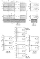
- the attachment plates have a number of functions, such as, inter alia, attaching and positioning screen panels, bearing the weight of one or more screen panels, deforming in order to allow movement of the screen, and providing separation between light emanating from projectors which are positioned directly next to or above one another.
- the stand 3 - which may or may not be present - may be composed in the same way and with the same profile sections 15, 16, 17, but is not described in further detail here.
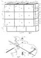
- All the screen panels 12 have the holes 28 at the same positions.
- the positions of the various holes 28 along a similar (horizontal or vertical) edge are all at the same positions and are distributed symmetrically with respect to the centre of the edge in question. Therefore, when installed correctly, for two mutually contacting screen panels 12 there is always, for each hole 28 on one screen panel 12, a corresponding hole 28 on the other screen panel 12, symmetrically with respect to the seam between the two screen panels 12.
- the joining wire 11 also positions the attachment plate 29 with respect to the seam 4 between the two screen panels 12.
- a slot 33 is formed in the thread section of the bolt 31.
- a bolt 31 is inserted through a hole 30 in the attachment plate 29, the thread section of the bolt 31 sliding over the two limbs of the joining wire 11, after which the nut 32 is screwed onto the bolt 31.
- the two limbs of the joining wire 11 are pressed against the attachment plate 29.
- Fig. 5 shows that a fixed joining wire 11 can bend in the plane of the attachment plate 29, to permit a move of the joined screen panels 12 with reference to the attachment plate 29, when the screen panels 12 and the attachment plate 29 do expand/shrink differently.
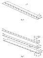
- a horizontal attachment plate 20 as illustrated in Fig. 6 is composed of a plurality of parts which are fixed to one another.
- Fig. 7 is a spatially exploded drawing of a horizontal attachment plate 20, showing a relatively thick bottom metal plate 34, a relatively thin middle metal plate 35 and a top plastic plate 36.
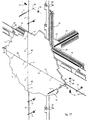
- Fig. 17 shows the intersection between two horizontal profile sections 15, two vertical profile sections 16 and a lateral profile section 17.
- a single extruded section is used for the horizontal, vertical and lateral profile sections 15, 16 and 17.
- the horizontal profile sections 15 are longer than the vertical profile sections 16 to obtain an aspect ratio of 4/3.
- the profile sections 15, 16, 17 have four equal sides in which a T-slot is provided for fixing profile sections to one another or for the fixation of other items to the profile sections.
- the horizontal and vertical profile sections 15, 16 are all fixed to the same lateral profile section 17 via attachment elements 27 and using coach bolts and nuts as described in BE-9601054.
- the bottom metal plate 69 has two perpendicular planes, being a plane 70 and a raised edge 71.
- the raised edge 71 are holes 72 for the fixation of the bottom metal plate 69 to the supporting structure 13 e.g. by means of bolts 66 and nuts 67 as shown in fig. 17.
- the plane 70 of the bottom metal plate 69 are multiple combinations of a hole 73, a lip 74 and a slot 75, these said combinations being parts of the join of the bottom metal plate 69 to the top metal plate 68 as further described.
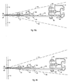
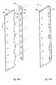
- Fig. 21a the conditions are assumed to be optimal, i.e. correct installation at the nominal ambient temperature using components of nominal dimensions, so that the front metal plate 80 is at right angles to the rear metal plate 81.
Landscapes
- Engineering & Computer Science (AREA)
- Multimedia (AREA)
- Signal Processing (AREA)
- Physics & Mathematics (AREA)
- General Physics & Mathematics (AREA)
- Overhead Projectors And Projection Screens (AREA)
- Transforming Electric Information Into Light Information (AREA)
- Projection Apparatus (AREA)
Description
- A light shielding plate is immovably fixed to the supporting frame body. Therefore, in the longitudinal direction said shielding plate cannot really move, it can only expand a little, which limits the movement of the corresponding seam attached to it. However, when the light shielding plate can bends, it is possible for the seam to move in a direction perpendicular to the longitudinal direction of the corresponding shielding plate.
- At the short extremities of the light shielding plates, however, the perpendicular movement of the seam is limited by the light shielding plates which are attached at right angles with respect to the considered shielding plate, which light shielding plates cannot move in their longitudinal direction, as explained hereinabove. Therefore, at the short extremities of the light shielding plates, it is impossible for the seam to move in a direction perpendicular to the longitudinal direction of the corresponding shielding plate.
Claims (26)
- Projection screen (9) for image reproduction devices, comprising a screen (10) which is assembled from a plurality of screen panels (12), a plurality of attachment plates (20,21) and a supporting structure (13), the attachment plates (20, 21) comprising at least one part to which screen panels (12) are joined, mutually contacting screen panels (12) and attachment plates (20,21) being drawn together by means of joining wires (11), and the said attachment plates (20, 21) being joined to the said supporting structure (13), characterised in that, of at least some of the said attachment plates (20, 21), at least that part to which screen panels (12) are joined can perform a guided linear move in the direction along the line of intersection between the plane of the respective attachment plate (20, 21) and the plane defined by the surface of the screen panels (12), and can bend in a direction perpendicular to the plane of the respective attachment plate (20, 21) or can hinge in a direction perpendicular to the plane of the respective attachment plate (20, 21) onto the supporting structure (13) or onto another part of the same attachment plate (20, 21) which has an immovable join to the said supporting structure (13).
- Projection screen (9) according to Claim 1, characterised in that the joining wires (11) are attached with both ends to a same attachment plate (20, 21).
- Projection screen (9) according to Claim 1 or 2, characterised in that, for the attachment plates, use is made of horizontal attachment plates (20) and vertical attachment plates (21).
- Projection screen (9) according to Claim 3, characterised in that at least some of the horizontal attachment plates (20) are composed of a plurality of plates (34, 35, 36; 68, 69) which are joined to one another and one of which is attached to the supporting structure (13) and to one of which the screen panels (12) are fixed.
- Projection screen (9) according to Claim 3 or 4, characterised in that at least some of the vertical attachment plates (21) consist of a single plate which can be attached to the supporting structure (13) and to which screen panels (12) can be fixed.
- Projection screen (9) according to Claim 3 or 4, characterised in that at least some of the vertical attachment plates (21) are composed of a plurality of plates (80, 81) which are joined to one another and one of which is attached to the supporting structure (13) and to one of which the screen panels (12) are fixed.
- Projection screen (9) according to any of Claims 4 to 6, characterised in that the plate (36, 21) to which the screen panels (12) are fixed is made from a non-transparent, black and matt plastic which has approximately the same coefficient of expansion as that of the material used for the screen panels (12).
- Projection screen (9) according to any of Claims 4 to 6, characterised in that the plate (36) to which the screen panels (12) are fixed is made from metal.
- Projection screen (9) according to one of the preceding claims, characterised in that the screen panels (12) are optical panels onto which it is possible to project, such as a Fresnel lens, a lenticular or a combination of the two.
- Projection screen (9) according to one of the preceding claims, characterised in that the attachment plates (20, 21) are provided with small holes (30) for fixing the joining wires (11).
- Projection screen (9) according to one of the preceding claims, characterised in that the joining wires (11) are U-shaped.
- Projection screen (9) according to one of the preceding claims, characterised in that the joining wires (11) are made from a material selected from metal or plastic.
- Projection screen (9) according to one of the preceding claims, characterised in that the joining wires (11) are fixed to the attachment plates (20, 21) using a bolt (31) and a nut (32).
- Projection screen (9) according to one of Claims 3 to 13, characterised in that each horizontal attachment plate (20), apart from the top one, bears the weight of the screen panel (12) which is attached thereto and stands physically above it.
- Projection screen (9) according to one of Claims 3 to 13, characterised in that the top horizontal attachment plates (20) bear the weight of all the screen panels (12) situated in a column beneath them, and in that the other horizontal attachment plates (20) do not have a weight-bearing function.
- Projection screen (9) according to one of Claims 3 to 13, characterised in that the bottom horizontal attachment plates (20) bear the weight of all the screen panels (12) situated in a column above them, and in that the other horizontal attachment plates (20) do not have a weight-bearing function.
- Projection screen (9) according to one of the preceding claims, characterised in that deformable and non-deformable attachment plates (20, 21) are used, by deformable being meant bendable and/or containing at least two parts which can longitudinally move with respect to one another and/or containing at least two parts hinging to one another.
- Projection screen (9) according to Claim 17, characterised in that, of all the columns of vertical attachment plates (21) standing one above the other, there is at least one column in which all the vertical attachment plates (21) are non-deformable.
- Projection screen (9) according to Claim 17 or 18, characterised in that, of all the rows of mutually adjacent horizontal attachment plates (20), there is at least one row in which all the horizontal attachment plates (20) are non-deformable.
- Projection screen (9) according to one of the preceding claims, characterised in that attachment points for projectors (22) are provided in the supporting structure (13).
- Projection screen (9) according to one of the preceding claims, characterised in that the screen panels (12) lie in one plane.
- Projection screen (9) according to one of Claims 1 to 20, characterised in that the screen panels (12) are planar and in that the surface formed by the screen panels (12) is curved.
- Projection screen (9) according to one of Claims 1 to 20, characterised in that the screen panels (12) and the surface formed by the screen panels (12) are curved.
- Projection screen (9) according to one of the preceding claims, characterised in that the screen panels (12) comprise a plurality of layers, of which at least one layer is attached to the attachment plates (20, 21) with the aid of the joining wires (11).
- Projection screen (9) according to one of the preceding claims, characterised in that any point of the screen surface (9) can make a move in any direction within the surface formed by the screen panels, whereby the said move is guided in two directions.
- Projection screen (9) according to one of the preceding claims, characterised in that all the screen panels (12) have the same dimensions.
Applications Claiming Priority (3)
| Application Number | Priority Date | Filing Date | Title |
|---|---|---|---|
| BE9700736 | 1997-09-09 | ||
| BE9700736A BE1011359A5 (en) | 1997-09-09 | 1997-09-09 | PROJECTION FOR ADDITION AND / OR superimposed DISPLAY DEVICES. |
| PCT/BE1998/000133 WO1999013377A1 (en) | 1997-09-09 | 1998-09-09 | Projection screen for image reproduction devices which are positioned next to and/or above one another |
Publications (2)
| Publication Number | Publication Date |
|---|---|
| EP1012666A1 EP1012666A1 (en) | 2000-06-28 |
| EP1012666B1 true EP1012666B1 (en) | 2001-10-31 |
Family
ID=3890721
Family Applications (1)
| Application Number | Title | Priority Date | Filing Date |
|---|---|---|---|
| EP98942399A Expired - Lifetime EP1012666B1 (en) | 1997-09-09 | 1998-09-09 | Projection screen for image reproduction devices which are positioned next to and/or above one another |
Country Status (6)
| Country | Link |
|---|---|
| US (1) | US6335829B1 (en) |
| EP (1) | EP1012666B1 (en) |
| BE (1) | BE1011359A5 (en) |
| DE (1) | DE69802297T2 (en) |
| ES (1) | ES2167926T3 (en) |
| WO (1) | WO1999013377A1 (en) |
Cited By (1)
| Publication number | Priority date | Publication date | Assignee | Title |
|---|---|---|---|---|
| US9936177B2 (en) | 2014-02-28 | 2018-04-03 | Barco N.V. | Seamless tiled displays |
Families Citing this family (23)
| Publication number | Priority date | Publication date | Assignee | Title |
|---|---|---|---|---|
| CA2256871A1 (en) * | 1998-12-22 | 2000-06-22 | Geoff Gosling | Method for supporting one or more seamless rear projector screens |
| RU2257602C2 (en) * | 2003-05-06 | 2005-07-27 | Общество с ограниченной ответственностью "АР Технологические Исследования" | Projector (versions) |
| DE102005056720A1 (en) * | 2005-11-29 | 2007-05-31 | Barco Control Rooms Gmbh | Projection module for large-area projection screen, has one frame part that is movable opposite to another frame part in displacement direction, and spring unit that produces small reset force during movement between frame parts |
| US9047039B2 (en) | 2007-05-14 | 2015-06-02 | Christie Digital Systems Usa, Inc. | Configurable imaging system |
| US7965257B2 (en) | 2007-05-14 | 2011-06-21 | Christie Digital Systems Usa, Inc. | Configurable imaging system |
| US7961157B2 (en) | 2007-05-14 | 2011-06-14 | Christie Digital Systems Usa, Inc. | Configurable imaging system |
| RU2388032C2 (en) * | 2008-05-06 | 2010-04-27 | Общество с ограниченной ответственностью "АР Технологические Исследования" | Projector (versions) |
| RU2369891C1 (en) * | 2008-05-16 | 2009-10-10 | Общество с ограниченной ответственностью "АР Технологические Исследования" | Projection device |
| US7918565B2 (en) | 2008-07-31 | 2011-04-05 | Christie Digital Systems Usa, Inc. | Expanding chassis for imaging systems |
| US8611072B2 (en) | 2010-05-17 | 2013-12-17 | Christie Digital Systems Usa, Inc. | Thermal actuator for configurable imaging systems |
| US9530397B2 (en) * | 2012-03-06 | 2016-12-27 | Reald Inc. | Light efficient acoustically transmissive front projection screens |
| CN102591122B (en) * | 2012-03-16 | 2015-04-08 | 北京环宇蓝博科技有限公司 | Traversing splicing screen |
| CN103529633B (en) * | 2013-11-04 | 2015-09-02 | 广东威创视讯科技股份有限公司 | A kind of connecting-piece structure for connecting Mosaic screen |
| US20150187237A1 (en) | 2013-12-31 | 2015-07-02 | Ultravision Holdings, Llc | System and Method for a Modular Multi-Panel Display |
| US9195281B2 (en) | 2013-12-31 | 2015-11-24 | Ultravision Technologies, Llc | System and method for a modular multi-panel display |
| US9416551B2 (en) | 2013-12-31 | 2016-08-16 | Ultravision Technologies, Llc | Preassembled display systems and methods of installation thereof |
| US9582237B2 (en) | 2013-12-31 | 2017-02-28 | Ultravision Technologies, Llc | Modular display panels with different pitches |
| CN104932190A (en) * | 2014-03-17 | 2015-09-23 | 上海壬务信息科技有限公司 | Improvement technology for screen connection |
| JP2015200710A (en) * | 2014-04-04 | 2015-11-12 | パナソニック株式会社 | Display device mounting metal fitting and display device mounting fixture |
| CN208850095U (en) | 2014-05-14 | 2019-05-10 | 巴科股份有限公司 | Electronic system |
| US10706770B2 (en) | 2014-07-16 | 2020-07-07 | Ultravision Technologies, Llc | Display system having module display panel with circuitry for bidirectional communication |
| US9740089B1 (en) * | 2016-11-10 | 2017-08-22 | The Elumenati, Llc | Modular curved projection screen |
| CN106647130B (en) * | 2017-03-07 | 2018-09-28 | 海信集团有限公司 | back projection splicing unit, system and back projection splicing unit adjusting method |
Family Cites Families (9)
| Publication number | Priority date | Publication date | Assignee | Title |
|---|---|---|---|---|
| JPS6488531A (en) * | 1987-09-30 | 1989-04-03 | Hitachi Ltd | Back surface projection type device |
| JP2898673B2 (en) * | 1989-05-10 | 1999-06-02 | 株式会社日立製作所 | Multi-screen projector and projector device |
| US5085495A (en) * | 1990-02-28 | 1992-02-04 | Hitachi, Ltd. | Multi-screen projector |
| JP3085726B2 (en) * | 1991-04-19 | 2000-09-11 | 株式会社日立製作所 | Multi-projection device |
| NO174990C (en) * | 1992-02-07 | 1994-08-10 | Dag Vilnes | Method of mounting or disassembling modules in a panel structure as well as a panel structure using the method |
| EP0650295B1 (en) * | 1993-10-21 | 1999-07-21 | Kabushiki Kaisha Toshiba | Multiscreen display and method for assembling the same |
| JPH08152677A (en) * | 1994-11-30 | 1996-06-11 | Mitsubishi Electric Corp | Multi vision device |
| EP0764875A1 (en) * | 1995-09-21 | 1997-03-26 | Kabushiki Kaisha Toshiba | Multiscreen displaying apparatus and screen fitting structure |
| US6084707A (en) * | 1996-10-04 | 2000-07-04 | Kuraray Co., Ltd. | Transmission-type screen |
-
1997
- 1997-09-09 BE BE9700736A patent/BE1011359A5/en not_active IP Right Cessation
-
1998
- 1998-09-09 ES ES98942399T patent/ES2167926T3/en not_active Expired - Lifetime
- 1998-09-09 EP EP98942399A patent/EP1012666B1/en not_active Expired - Lifetime
- 1998-09-09 WO PCT/BE1998/000133 patent/WO1999013377A1/en not_active Ceased
- 1998-09-09 DE DE69802297T patent/DE69802297T2/en not_active Expired - Lifetime
-
2000
- 2000-03-07 US US09/520,608 patent/US6335829B1/en not_active Expired - Lifetime
Cited By (1)
| Publication number | Priority date | Publication date | Assignee | Title |
|---|---|---|---|---|
| US9936177B2 (en) | 2014-02-28 | 2018-04-03 | Barco N.V. | Seamless tiled displays |
Also Published As
| Publication number | Publication date |
|---|---|
| WO1999013377B1 (en) | 1999-04-29 |
| US6335829B1 (en) | 2002-01-01 |
| BE1011359A5 (en) | 1999-07-06 |
| DE69802297D1 (en) | 2001-12-06 |
| WO1999013377A1 (en) | 1999-03-18 |
| DE69802297T2 (en) | 2002-07-11 |
| ES2167926T3 (en) | 2002-05-16 |
| EP1012666A1 (en) | 2000-06-28 |
Similar Documents
| Publication | Publication Date | Title |
|---|---|---|
| US6335829B1 (en) | Projection screen for image reproduction devices which are positioned next to and/or above one another | |
| US4866530A (en) | Multiple screen, modular video display projection system | |
| US5818639A (en) | Multiscreen displaying apparatus and screen fitting structure | |
| US5206760A (en) | Multiprojection apparatus | |
| EP0834766B1 (en) | Transmission-type screen | |
| JP2755173B2 (en) | Rear-projection television receiver | |
| US20160216601A1 (en) | Seamless projection screen for fast installation | |
| EP0567317A1 (en) | Projection television set | |
| EP0193088B1 (en) | Transmission type screen apparatus | |
| JP2989021B2 (en) | Transmission screen | |
| EP0119762B1 (en) | Improvements in or relating to the tensioning of flexible sheets across frames | |
| JPH08152677A (en) | Multi vision device | |
| US6324000B1 (en) | Seam between adjacent visualization screens | |
| JP3417492B2 (en) | Transmission projection screen | |
| JP3332129B2 (en) | Method of manufacturing transmission projection screen | |
| JPH08140023A (en) | Multi vision | |
| US20050264768A1 (en) | Wall structure | |
| JPH06130495A (en) | Combination projection display | |
| JPH06245177A (en) | Multi vision | |
| JP4810100B2 (en) | Rear projection type screen and rear projection type projector | |
| JP2000347299A (en) | Multi-projection system | |
| EP0945008B1 (en) | Light shield for image reproduction devices placed next to and/or above one another | |
| JPH06294998A (en) | Multivision | |
| JPH06105336B2 (en) | Projection tv | |
| JPH06105337B2 (en) | Projection tv |
Legal Events
| Date | Code | Title | Description |
|---|---|---|---|
| PUAI | Public reference made under article 153(3) epc to a published international application that has entered the european phase |
Free format text: ORIGINAL CODE: 0009012 |
|
| 17P | Request for examination filed |
Effective date: 20000404 |
|
| AK | Designated contracting states |
Kind code of ref document: A1 Designated state(s): DE ES FR GB GR IT NL SE |
|
| GRAG | Despatch of communication of intention to grant |
Free format text: ORIGINAL CODE: EPIDOS AGRA |
|
| GRAG | Despatch of communication of intention to grant |
Free format text: ORIGINAL CODE: EPIDOS AGRA |
|
| GRAH | Despatch of communication of intention to grant a patent |
Free format text: ORIGINAL CODE: EPIDOS IGRA |
|
| 17Q | First examination report despatched |
Effective date: 20010319 |
|
| GRAH | Despatch of communication of intention to grant a patent |
Free format text: ORIGINAL CODE: EPIDOS IGRA |
|
| GRAA | (expected) grant |
Free format text: ORIGINAL CODE: 0009210 |
|
| AK | Designated contracting states |
Kind code of ref document: B1 Designated state(s): DE ES FR GB GR IT NL SE |
|
| REF | Corresponds to: |
Ref document number: 69802297 Country of ref document: DE Date of ref document: 20011206 |
|
| RAP2 | Party data changed (patent owner data changed or rights of a patent transferred) |
Owner name: BARCO N.V. |
|
| REG | Reference to a national code |
Ref country code: GB Ref legal event code: IF02 |
|
| PG25 | Lapsed in a contracting state [announced via postgrant information from national office to epo] |
Ref country code: GR Free format text: LAPSE BECAUSE OF FAILURE TO SUBMIT A TRANSLATION OF THE DESCRIPTION OR TO PAY THE FEE WITHIN THE PRESCRIBED TIME-LIMIT Effective date: 20020201 |
|
| NLT2 | Nl: modifications (of names), taken from the european patent patent bulletin |
Owner name: BARCO N.V. |
|
| ET | Fr: translation filed | ||
| REG | Reference to a national code |
Ref country code: ES Ref legal event code: FG2A Ref document number: 2167926 Country of ref document: ES Kind code of ref document: T3 |
|
| PLBE | No opposition filed within time limit |
Free format text: ORIGINAL CODE: 0009261 |
|
| STAA | Information on the status of an ep patent application or granted ep patent |
Free format text: STATUS: NO OPPOSITION FILED WITHIN TIME LIMIT |
|
| 26N | No opposition filed | ||
| PGFP | Annual fee paid to national office [announced via postgrant information from national office to epo] |
Ref country code: IT Payment date: 20100927 Year of fee payment: 13 |
|
| PGFP | Annual fee paid to national office [announced via postgrant information from national office to epo] |
Ref country code: SE Payment date: 20110923 Year of fee payment: 14 |
|
| PGFP | Annual fee paid to national office [announced via postgrant information from national office to epo] |
Ref country code: NL Payment date: 20110929 Year of fee payment: 14 |
|
| REG | Reference to a national code |
Ref country code: NL Ref legal event code: V1 Effective date: 20130401 |
|
| PG25 | Lapsed in a contracting state [announced via postgrant information from national office to epo] |
Ref country code: SE Free format text: LAPSE BECAUSE OF NON-PAYMENT OF DUE FEES Effective date: 20120910 |
|
| REG | Reference to a national code |
Ref country code: SE Ref legal event code: EUG |
|
| PG25 | Lapsed in a contracting state [announced via postgrant information from national office to epo] |
Ref country code: NL Free format text: LAPSE BECAUSE OF NON-PAYMENT OF DUE FEES Effective date: 20130401 Ref country code: IT Free format text: LAPSE BECAUSE OF NON-PAYMENT OF DUE FEES Effective date: 20120909 |
|
| PGFP | Annual fee paid to national office [announced via postgrant information from national office to epo] |
Ref country code: ES Payment date: 20130927 Year of fee payment: 16 |
|
| PGFP | Annual fee paid to national office [announced via postgrant information from national office to epo] |
Ref country code: FR Payment date: 20130919 Year of fee payment: 16 Ref country code: GB Payment date: 20130916 Year of fee payment: 16 |
|
| GBPC | Gb: european patent ceased through non-payment of renewal fee |
Effective date: 20140909 |
|
| REG | Reference to a national code |
Ref country code: FR Ref legal event code: ST Effective date: 20150529 |
|
| PG25 | Lapsed in a contracting state [announced via postgrant information from national office to epo] |
Ref country code: GB Free format text: LAPSE BECAUSE OF NON-PAYMENT OF DUE FEES Effective date: 20140909 |
|
| PG25 | Lapsed in a contracting state [announced via postgrant information from national office to epo] |
Ref country code: FR Free format text: LAPSE BECAUSE OF NON-PAYMENT OF DUE FEES Effective date: 20140930 |
|
| REG | Reference to a national code |
Ref country code: ES Ref legal event code: FD2A Effective date: 20151027 |
|
| PG25 | Lapsed in a contracting state [announced via postgrant information from national office to epo] |
Ref country code: ES Free format text: LAPSE BECAUSE OF NON-PAYMENT OF DUE FEES Effective date: 20140910 |
|
| PGFP | Annual fee paid to national office [announced via postgrant information from national office to epo] |
Ref country code: DE Payment date: 20170928 Year of fee payment: 20 |
|
| REG | Reference to a national code |
Ref country code: DE Ref legal event code: R071 Ref document number: 69802297 Country of ref document: DE |