EP1012445B2 - Blade for a turbo-machine - Google Patents
Blade for a turbo-machine Download PDFInfo
- Publication number
- EP1012445B2 EP1012445B2 EP98951240A EP98951240A EP1012445B2 EP 1012445 B2 EP1012445 B2 EP 1012445B2 EP 98951240 A EP98951240 A EP 98951240A EP 98951240 A EP98951240 A EP 98951240A EP 1012445 B2 EP1012445 B2 EP 1012445B2
- Authority
- EP
- European Patent Office
- Prior art keywords
- blade
- cross
- vane
- end region
- another
- Prior art date
- Legal status (The legal status is an assumption and is not a legal conclusion. Google has not performed a legal analysis and makes no representation as to the accuracy of the status listed.)
- Expired - Lifetime
Links
- 230000002093 peripheral effect Effects 0.000 claims description 3
- 238000006073 displacement reaction Methods 0.000 description 11
- 230000005484 gravity Effects 0.000 description 4
- 238000005452 bending Methods 0.000 description 3
- 239000012530 fluid Substances 0.000 description 2
- 230000006978 adaptation Effects 0.000 description 1
- 238000005336 cracking Methods 0.000 description 1
- 238000005516 engineering process Methods 0.000 description 1
- 230000007613 environmental effect Effects 0.000 description 1
- 239000003344 environmental pollutant Substances 0.000 description 1
- 238000000034 method Methods 0.000 description 1
- 231100000719 pollutant Toxicity 0.000 description 1
- 238000007493 shaping process Methods 0.000 description 1
Images
Classifications
-
- F—MECHANICAL ENGINEERING; LIGHTING; HEATING; WEAPONS; BLASTING
- F01—MACHINES OR ENGINES IN GENERAL; ENGINE PLANTS IN GENERAL; STEAM ENGINES
- F01D—NON-POSITIVE DISPLACEMENT MACHINES OR ENGINES, e.g. STEAM TURBINES
- F01D5/00—Blades; Blade-carrying members; Heating, heat-insulating, cooling or antivibration means on the blades or the members
- F01D5/12—Blades
- F01D5/14—Form or construction
- F01D5/141—Shape, i.e. outer, aerodynamic form
-
- F—MECHANICAL ENGINEERING; LIGHTING; HEATING; WEAPONS; BLASTING
- F01—MACHINES OR ENGINES IN GENERAL; ENGINE PLANTS IN GENERAL; STEAM ENGINES
- F01D—NON-POSITIVE DISPLACEMENT MACHINES OR ENGINES, e.g. STEAM TURBINES
- F01D5/00—Blades; Blade-carrying members; Heating, heat-insulating, cooling or antivibration means on the blades or the members
- F01D5/12—Blades
- F01D5/14—Form or construction
- F01D5/141—Shape, i.e. outer, aerodynamic form
- F01D5/145—Means for influencing boundary layers or secondary circulations
Definitions
- the invention relates to a blade for a turbomachine, wherein the blade is directed along a blade axis and along this blade axis has adisproportionateend Scheme, a Kopfend Scheme and disposed therebetween a central region and a cross-sectional area perpendicular to the blade axis.
- the EP-A-0 704 602 deals with the design of a turbine vane in an intermediate stator of a steam turbine directed along a turbine axis.
- the blade extends along a radially directed blade axis and has a pressure side and a suction side as well as an entry edge and an exit edge.
- the blade along the radial direction is configured such that the pressure side has a convex curvature behavior from a blade root area to a blade head area opposite the blade root area along the blade axis.
- the convex curvature of the pressure side of the airfoil is achieved in the radial direction by a rotating displacement of the cross sections around the straight trailing edge.
- the curvature is achieved in that, in the case of radially successive, spaced-apart cross-sectional profiles, the setting angle (bitangential angle) with respect to the turbine axis is varied in a parabolic manner by a corresponding rotation of the cross-sectional profiles around the fixed common exit edge.
- the channel width for the steam can thus be reduced in the blade head area and in the blade root area and increased in an intermediate blade center area. This results in a displacement of a portion of the vapor mass flow away from the two lossy edge regions of the turbine vane.
- Such cylindrical blades have parallel to the blade axis pressure and suction sides and thus have neither a twist nor an inclination.
- so-called twisted turbine blades are described, which have over their height an increasing rotation and a changing blade profile.
- an axial turbine such as a steam turbine or a gas turbine having a plurality of circumferentially spaced vanes.
- the vanes used are wound over their height and have a changing inlet angle.
- the change in the inlet angle increases from a certain height measured from the blade root (root) continuously in the region of the tip of the vane over-linear.
- the distortion also increases continuously over the height of the vane.
- the cross-sectional profile of the vane changes continuously from the blade root to the blade tip, with the vane becoming increasingly slender.
- the size and shape of the vane are taken into account.
- inlet guide vanes are arranged along the gas flow path in front of the blades and vanes. These inlet or inlet guide vanes have a curved cross-section, except in the region of the walls.
- the central blade part with the curved cross section goes in each wall area in a smooth and continuously curved surface in the non-curved cross-sectional profile in the wall areas over. Over the height of the inlet guide vane thus continuously change the cross-sectional profiles of the airfoil.
- the inlet angle remains constant over the entire height of the inlet guide vane.
- a vane ring for an axial turbine is described with vanes, wherein the guide vanes are arranged between an inner and an outer ring and the profile thickness of the airfoil changes in proportion to the blade pitch.
- the change in the blade profile is made over the height of the vane in that there is no change in the shape of the leading edge (pressure side), but the projection on the trailing edge gradually increases in size over the height while increasing the thickness of the vane.
- the profile change is in this case carried out so that the thickness of the vane increases while their chord length remains the same.
- Such a vane ring is applicable to steam turbines, gas turbines and compressors.
- Turbine blades according to the preamble of claim 1 are known from the article " Development of three-dimensional stage viscous time marching method for short height stages "by G. Singh, PJ Walker, BR Haller, in:” VDI Reports No. 1185, 1995, pp. 157-179 , known.
- the object of the invention is to provide a blade with low flow losses for a turbomachine.
- the object directed to a blade for a turbomachine is achieved by such a blade which is directed along a blade axis and along this blade axis has a predominantlyend Scheme, a Kopfend Scheme and between a central region and a vertical axis to the blade profile cross-sectional profile, wherein axially in the direction of the blade axis spaced apart cross-sectional profiles from the prescribedend Scheme to the central region and from the Kopfend Scheme to the central region in the same direction are offset from each other and wherein in thepreparingend Scheme and / or Kopfend Scheme axially spaced cross-sectional profiles are rotated by a differential angle to each other, wherein the blade is cylindrical in the central region.
- the blade is cylindrical in the central region.
- the sides (pressure side, suction side) of the blade thus run parallel to the blade axis.
- the axially spaced-apart cross-sectional areas in the pleasingend Scheme and the head end region are rotated rectified towards the central region.
- the rotation is withdrawn.
- the blade is preferably designed for placement in a blade ring, which has a circumferential direction, wherein the cross-sectional direction coincides locally with the circumferential direction.
- a bend takes place in the circumferential direction with a simultaneous rotation (angle adaptation) in the end regions of the blade, whereby a reduction of flow losses and thus an increase in the efficiency of a turbomachine can be achieved.
- an increase in the mechanical discharge energy at the same thermal energy use and on the other hand a reduction of the thermal energy input and thus the environmental impact of pollutant emissions at constant discharge energy compared to purely cylindrical or purely inclined or purely curved blades achieved.
- the cross-sectional profiles are preferably included a rotation with respect to their centroid or with respect to the blade axis (if different, for example, by inhomogeneous mass distribution) rotated.
- the rotational angle occurring in the following is referred to as a stagger angle and a rotation is performed as a stagger angle change.
- the cross-sectional profile along the blade axis is preferably the same everywhere.
- the cross-sectional profile does not change over the height of the blade.
- the cross-sectional area of the cross-sectional profiles is constant.
- the blade preferably has a combination of a circumferential deflection of the center of gravity of the cross-sectional profiles (bending in the circumferential direction) and a staggering of the cross-sectional profiles (without changing the profiling) in the head end and satisfiedend Scheme (hub and housing area).
- the blade is preferably designed as a vane or blade of a steam turbine, in particular a high pressure or medium pressure steam turbine.
- the blade preferably has a small length to width ratio, as is the case in particular for blades for a high-pressure steam turbine.
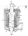
- FIG. 1 shows a flow machine, a high-pressure steam turbine 11, in a longitudinal section, which is directed along a turbine axis 17.
- the steam turbine 11 has a turbine shaft 20 directed along the turbine axis 17, which is surrounded by a turbine housing 18.
- the steam turbine 11 has an inflow region 12 for action fluid, superheated steam, and an outflow region 13 for the superheated steam.
- a blading region 14 is provided in the blading area 14.
- guide vanes which are combined in the axial direction alternately one after the other in each case in a corresponding blade ring 21 follow 9 and Blades 8.
- Each blade 8 and each vane 9 has along a blade axis 2 (see FIG.
- the rotor blades 8 and / or guide vanes 9 closest to the inflow region 12 are each designed as a blade 1, which is inclined and twisted in the foot end region 3 and in the head end region 4.
- Blades 8 closest to the outflow region 13 and guide vanes 9 are each designed as twisted blades 19 with an increasing rotation and changing cross-sectional profile over the blade axis 2.
- In the blading region 14 axially between the inclined and twisted blades 1 and the twisted blades 19 are arranged purely cylindrical blades 16 whose suction and pressure sides are each parallel to the blade axis 2.
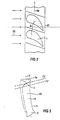
- FIG. 2 shows a detail of a blade ring 21 in which blades 1 are arranged next to one another in the circumferential direction 6a.
- the blade ring 21 is unwound along the circumferential direction 6a and shown with only two blades 1.
- the circumferential direction 6 a corresponds to the circumference of the turbine shaft 20 in a section perpendicular to the turbine axis 17.
- the main flow direction 22 of the steam flowing in the steam turbine 11 is perpendicular to the circumferential direction 6 a of the blade ring 21.
- FIG. 3 shows, in a three-dimensional view, the blade leaf area 23 of a blade 1 directed along a blade axis 2.
- the airfoil region 23 has a foot end region 3, a head end region 4 and a middle region 10 therebetween.
- a shroud possibly following the head end region 4 is likewise not shown.
- the turbine blade 1 is inclined in a cross-sectional direction 6, which preferably corresponds to the circumferential direction 6a of the blade ring 21, and rotated in the axial direction by a differential angle ⁇ (see FIGS. 4 and 5).
- the in theticianend Scheme 3 to the central region 10 towards increasing rotation and increasing circumferential deflection corresponds to the same rotation and circumferential bend as in Kopfend Scheme 4.
- the amount of backward rotation and backward displacement over the head end region 4 is preferably the same as the displacement and twist in the foot end region 3.
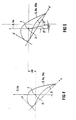
- the circumferential bend herein means a displacement of the cross-sectional profile 5, 5a in the direction of a cross-sectional direction 6, which preferably corresponds to the circumferential direction 6a of a blade ring 21.
- a rotation of the blade 1 is effected by a stagger angle change, i. a change of the angle ⁇ according to Figure 4 and Figure 5 by a rotation of the cross-sectional profile 5 about the blade axis 2, which preferably coincides with the gravity axis of the blade 1.
- this likewise corresponds to a rotation about the centroid 7 (center of gravity 7) of the cross-section profile 5, 5a.
- the cross-sectional profile 5, 5a, 5b is the same over the entire height of the airfoil region 23 for each cross-section, i. in particular that the cross-sectional shape and area are constant.
- the cross-sectional profile 5b shown in FIG. 5 is rotated relative to the cross-sectional profile 5a shown in FIG. 4 by the difference angle ⁇ and shifted by the displacement value ⁇ U. This corresponds to a change of the stagger angle ⁇ to the value of the stagger angle ⁇ '(FIG. 5).
- the edge losses i. the fluid mechanical losses in the vicinity of the turbine shaft and the turbine housing, can be up to about 30% of the total losses, a reduction of these edge losses due to the rotation and circumferential deflection of the blade in a steam turbine to an increase in efficiency.
- the degree of rotation and circumferential deflection can be adapted in each case to the fluidic conditions in a steam turbine.
- the central region is cylindrical.
Abstract
Description
Die Erfindung betrifft eine Schaufel für eine Strömungsmaschine, wobei die Schaufel entlang einer Schaufelachse gerichtet ist und entlang dieser Schaufelachse einen Fußendbereich, einen Kopfendbereich und dazwischen angeordnet einen Mittelbereich sowie ein Querschnittsbereich senkrecht zur Schaufelachse aufweist.The invention relates to a blade for a turbomachine, wherein the blade is directed along a blade axis and along this blade axis has a Fußendbereich, a Kopfendbereich and disposed therebetween a central region and a cross-sectional area perpendicular to the blade axis.
Der Wirkungsgrad einer Strömungsmaschine, insbesondere einer Dampfturbine, wird durch auftretende Strömungsverluste verringert. Mit der Verbesserung des Wirkungsgrades und damit auch der Reduzierung solcher Strömungsverluste befaßt sich z.B. der Artikel "
Die
In einer besonders bevorzugten Ausgestaltung wird die Krümmung dadurch erreicht, daß bei radial aufeinanderfolgenden, voneinander beabstandeten Querschnittsprofilen durch eine entsprechende Rotation der Querschnittsprofile um die feste gemeinsame Austrittskante der Einstellwinkel (Bitangentialwinkel) bezüglich der Turbinenachse parabelförmig variiert wird. Die Kanalweite für den Dampf kann somit im Schaufelkopfbereich und im Schaufelfußbereich reduziert und in einem dazwischenliegenden Schaufelmittenbereich erhöht werden. Dies führt zu einer Verlagerung eines Teils des Dampf-Massenstromes, weg von den beiden verlustbehafteten Randbereichen der Turbinenleitschaufel.In a particularly preferred embodiment, the curvature is achieved in that, in the case of radially successive, spaced-apart cross-sectional profiles, the setting angle (bitangential angle) with respect to the turbine axis is varied in a parabolic manner by a corresponding rotation of the cross-sectional profiles around the fixed common exit edge. The channel width for the steam can thus be reduced in the blade head area and in the blade root area and increased in an intermediate blade center area. This results in a displacement of a portion of the vapor mass flow away from the two lossy edge regions of the turbine vane.
In dem Artikel "
In der
In der Deutschen Auslegeschrift
In der Deutschen Auslegeschrift 28 41 616 ist ein Leitschaufelkranz für eine Axialturbine mit Leitschaufeln beschrieben, wobei die Leitschaufeln zwischen einem inneren und einem äußeren Ring angeordnet sind und die Profildicke des Schaufelblatts proportional zu der Schaufelteilung sich ändert. Die Änderung des Schaufelprofils erfolgt hierbei über die Höhe der Leitschaufel dadurch, daß keine Änderung in der Form der vorauseilenden Kante (Druckseite) stattfindet, sondern der Vorsprung auf der nacheilenden Kante an Größe über die Höhe allmählich zunimmt bei gleichzeitiger Zunahme der Dicke der Leitschaufel. Die Profiländerung wird hierbei so durchgeführt, daß die Dicke der Leitschaufel zunimmt, während ihre Sehnenlänge gleichbleibt. Ein solcher Leitschaufelkranz ist anwendbar bei Dampfturbinen, Gasturbinen sowie Kompressoren.In the German Auslesgeschrift 28 41 616 a vane ring for an axial turbine is described with vanes, wherein the guide vanes are arranged between an inner and an outer ring and the profile thickness of the airfoil changes in proportion to the blade pitch. The change in the blade profile is made over the height of the vane in that there is no change in the shape of the leading edge (pressure side), but the projection on the trailing edge gradually increases in size over the height while increasing the thickness of the vane. The profile change is in this case carried out so that the thickness of the vane increases while their chord length remains the same. Such a vane ring is applicable to steam turbines, gas turbines and compressors.
In der
Turbinenschaufeln gemäß Oberbegriff des Anspruchs 1 sind aus dem Artikel "
Aufgabe der Erfindung ist es, eine Schaufel mit geringen Strömungsverlusten für eine Strömungsmaschine anzugeben.The object of the invention is to provide a blade with low flow losses for a turbomachine.
Erfindungsgemäß wird die auf eine Schaufel für eine Strömungsmaschine gerichtete Aufgabe durch eine solche Schaufel gelöst, welche entlang einer Schaufelachse gerichtet ist und entlang dieser Schaufelachse einen Fußendbereich, einen Kopfendbereich sowie dazwischen einen Mittelbereich und ein zur Schaufelachse senkrechtes Querschnittsprofil aufweist, wobei axial in Richtung der Schaufelachse voneinander beabstandete Querschnittsprofile vom Fußendbereich zum Mittelbereich sowie vom Kopfendbereich zum Mittelbereich in dieselbe Richtung gegeneinander versetzt sind und wobei im Fußendbereich und/oder im Kopfendbereich axial voneinander beabstandete Querschnittsprofile um einen Differenzwinkel gegeneinander verdreht sind, wobei die Schaufel im Mittelbereich zylindrisch ausgeführt ist.According to the invention, the object directed to a blade for a turbomachine is achieved by such a blade which is directed along a blade axis and along this blade axis has a Fußendbereich, a Kopfendbereich and between a central region and a vertical axis to the blade profile cross-sectional profile, wherein axially in the direction of the blade axis spaced apart cross-sectional profiles from the Fußendbereich to the central region and from the Kopfendbereich to the central region in the same direction are offset from each other and wherein in the Fußendbereich and / or Kopfendbereich axially spaced cross-sectional profiles are rotated by a differential angle to each other, wherein the blade is cylindrical in the central region.
Bei einem Einbau der Schaufel in eine Turbine mit einer Turbinenwelle ist axial in Richtung der Schaufelachse gleichbedeutend mit radial in bezug auf die Turbinenwelle. Mit der Verschiebung von axial zueinander beabstandeten Querschnittsprofilen im Kopfendbereich sowie im Fußendbereich und einer zusätzlichen Verdrehung im Fußendbereich und/oder im Kopfendbereich wird eine Reduzierung der Strömungsverluste in den Randzonen (Kopfendbereich, Fußendbereich), welche der Nabe einer Turbinenwelle sowie dem Innenumfang eines Turbinengehäuses zugeordnet sind, erreicht. Die gleichgerichtete Verschiebung zum Mittelbereich hin bewirkt, daß die Turbinenschaufel bauchförmig senkrecht zur Schaufelachse geneigt (gebogen) ist. Mit einer zusätzlichen Verdrehung der axial zueinander beabstandeten Querschnittsprofile wird eine zusätzliche Erhöhung des Wirkungsgrades, d.h. eine Reduzierung der Strömungsverluste, erreicht. Je nach Ausdehnung der Schaufel in Richtung der Schaufelachse (Schaufellänge, Schaufelhöhe) zur Ausdehnung der Schaufel in einer Richtung senkrecht zur Schaufelachse (Schaufelbreite) und den Strömungsbedingungen bei Einsatz der Schaufel in einer Strömungsmaschine ist die Schaufel in dem Mittelbereich zylindrisch ausgeführt. Die Seiten (Druckseite, Saugseite) der Schaufel verlaufen mithin parallel zu der Schaufelachse.When the blade is installed in a turbine with a turbine shaft, axially in the direction of the blade axis is equivalent to radial with respect to the turbine shaft. With the displacement of axially spaced cross-sectional profiles in the head end region and in the Fußendbereich and an additional rotation in Fußendbereich and / or Kopfendbereich a reduction of flow losses in the edge zones (Kopfendbereich, Fußendbereich), which are associated with the hub of a turbine shaft and the inner circumference of a turbine housing , reached. The rectified displacement toward the central region causes the turbine blade to be bowed (bent) perpendicular to the blade axis. With an additional rotation of the axially spaced cross-sectional profiles, an additional increase in efficiency, i. a reduction in flow losses achieved. Depending on the extent of the blade in the direction of the blade axis (blade length, blade height) for expansion of the blade in a direction perpendicular to the blade axis (blade width) and the flow conditions when using the blade in a turbomachine, the blade is cylindrical in the central region. The sides (pressure side, suction side) of the blade thus run parallel to the blade axis.
Vorzugsweise sind die axial voneinander beabstandeten Querschnittsbereiche im Fußendbereich und im Kopfendbereich zum Mittelbereich hin gleichgerichtet gedreht. Hierdurch ist über die gesamte Höhe der Schaufel hinweg vom Kopfendbereich zum Fußendbereich hin die Verdrehung wieder zurückgenommen.Preferably, the axially spaced-apart cross-sectional areas in the Fußendbereich and the head end region are rotated rectified towards the central region. As a result, over the entire height of the blade away from the Kopfendbereich to Fußendbereich out the rotation is withdrawn.
Die Schaufel ist vorzugsweise zur Anordnung in einen Schaufelkranz ausgelegt, welcher eine Umfangsrichtung aufweist, wobei die Querschnittsrichtung lokal mit der Umfangsrichtung zusammenfällt. Hierdurch erfolgt in den Randzonen der Schaufel eine Biegung in Umfangsrichtung mit einer gleichzeitigen Drehung (Winkelanpassung) in den Endbereichen der Schaufel, wodurch eine Verringerung von Strömungsverlusten und somit eine Erhöhung des Wirkungsgrades einer Strömungsmaschine erreichbar ist. Insbesondere bei Dampfturbinen wird hierdurch einerseits eine Erhöhung der mechanischen Austrittsenergie bei gleichem thermischen Energieeinsatz sowie andererseits eine Reduktion des thermischen Energieeinsatzes und damit der Umweltbelastung durch Schadstoffausstoß bei gleichbleibender Austrittsenergie im Vergleich zu rein zylindrischen bzw. rein geneigten oder rein gebogenen Schaufeln erreicht.The blade is preferably designed for placement in a blade ring, which has a circumferential direction, wherein the cross-sectional direction coincides locally with the circumferential direction. As a result, in the edge zones of the blade, a bend takes place in the circumferential direction with a simultaneous rotation (angle adaptation) in the end regions of the blade, whereby a reduction of flow losses and thus an increase in the efficiency of a turbomachine can be achieved. In particular, in steam turbines on the one hand an increase in the mechanical discharge energy at the same thermal energy use and on the other hand, a reduction of the thermal energy input and thus the environmental impact of pollutant emissions at constant discharge energy compared to purely cylindrical or purely inclined or purely curved blades achieved.
Die Querschnittsprofile sind vorzugsweise bei einer Drehung bezüglich ihrem Flächenschwerpunkt oder bezüglich der Schaufelachse (falls abweichend z.B. durch inhomogene Massenverteilung) gedreht. Der dabei auftretende Drehwinkel wird im folgenden als Staffelwinkel und eine Durchführung der Drehung als Staffelwinkeländerung bezeichnet.The cross-sectional profiles are preferably included a rotation with respect to their centroid or with respect to the blade axis (if different, for example, by inhomogeneous mass distribution) rotated. The rotational angle occurring in the following is referred to as a stagger angle and a rotation is performed as a stagger angle change.
In einem Querschnitt senkrecht zur Schaufelachse ist das Querschnittsprofil entlang der Schaufelachse vorzugsweise überall gleich. Das Querschnittsprofil ändert sich mithin über die Höhe der Schaufel nicht. Hierbei ist vorzugsweise auch die Querschnittsfläche der Querschnittsprofile konstant. Die Schaufel weist hierbei vorzugsweise eine Kombination aus einer Umfangsauslenkung des Schwerpunkts der Querschnittsprofile (Biegung in Umfangsrichtung) und eine Staffelung der Querschnittsprofile (ohne Änderung der Profilierung) im Kopfend- und Fußendbereich (Naben- und Gehäusebereich) auf.In a cross-section perpendicular to the blade axis, the cross-sectional profile along the blade axis is preferably the same everywhere. The cross-sectional profile does not change over the height of the blade. In this case, preferably, the cross-sectional area of the cross-sectional profiles is constant. The blade preferably has a combination of a circumferential deflection of the center of gravity of the cross-sectional profiles (bending in the circumferential direction) and a staggering of the cross-sectional profiles (without changing the profiling) in the head end and Fußendbereich (hub and housing area).
Die Schaufel ist vorzugsweise als Leitschaufel oder Laufschaufel einer Dampfturbine, insbesondere einer Hochdruckoder Mitteldruckdampfturbine ausgeführt. Bevorzugt weist die Schaufel hierbei ein kleines Längen zu Breiten-Verhältnis auf, wie es insbesondere bei Schaufeln für eine Hochdruck-Dampfturbine der Fall ist.The blade is preferably designed as a vane or blade of a steam turbine, in particular a high pressure or medium pressure steam turbine. In this case, the blade preferably has a small length to width ratio, as is the case in particular for blades for a high-pressure steam turbine.
Anhand der in der Zeichnung dargestellten Ausführungsbeispiele werden die Schaufel für eine Strömungsmaschine sowie eine Dampfturbine näher erläutert. Es zeigen in teilweise schematisierter und nicht maßstäblicher Darstellung
- FIG 1
- einen Längsschnitt durch eine Hochdruck-Dampfturbine,
- FIG 2
- einen Querschnitt eines Ausschnitts durch einen Schaufelkranz,
- FIG 3
- eine räumliche Darstellung des Schaufelblattbereichs einer Schaufel,
- FIG 4
- einen Querschnitt durch den Schaufelblattbereich der Schaufel gemäß Figur 3 und
- FIG 5
- einen weiteren Querschnitt durch die
Schaufel gemäß Figur 3 axial in Richtung der Schaufelachse beabstandet von demQuerschnitt gemäß Figur 4.
- FIG. 1
- a longitudinal section through a high-pressure steam turbine,
- FIG. 2
- a cross-section of a section through a blade ring,
- FIG. 3
- a spatial representation of the blade area of a blade,
- FIG. 4
- a cross section through the airfoil portion of the blade according to Figure 3 and
- FIG. 5
- a further cross section through the blade according to Figure 3 axially in the direction of the blade axis spaced from the cross section of Figure 4.
Gleiche Bezugszeichen haben in sämtlichen Figuren jeweils die gleiche Bedeutung.The same reference numerals have the same meaning in all figures.
In Figur 1 ist eine Strömungsmaschine, eine Hochdruck-Dampfturbine 11, in einem Längsschnitt dargestellt, die entlang einer Turbinenachse 17 gerichtet ist. Die Dampfturbine 11 weist eine entlang der Turbinenachse 17 gerichtete Turbinenwelle 20 auf, welche von einem Turbinengehäuse 18 umgeben ist. Entlang der Turbinenachse 17 weist die Dampfturbine 11 einen Einströmbereich 12 für Aktionsfluid, Heißdampf, sowie einen Abströmbereich 13 für den Heißdampf auf. Axial zwischen Einströmbereich 12 und Abströmbereich 13 ist ein Beschaufelungsbereich 14 vorgesehen. In dem Beschaufelungsbereich 14 folgen in axialer Richtung alternierend hintereinander jeweils in einem entsprechenden Schaufelkranz 21 zusammengefaßte Leitschaufeln 9 und Laufschaufeln 8. Jede Laufschaufel 8 und jede Leitschaufel 9 weist entlang einer Schaufelachse 2 (siehe Figur 3) einen Fußendbereich 3, einen Kopfendbereich 4 und axial in Richtung der Schaufelachse 2 dazwischen angeordnet einen Mittelbereich 10 auf. Mit dem Fußendbereich 3 grenzt eine Laufschaufel 8 an die Turbinenwelle 20 und eine Leitschaufel 9 an das Turbinengehäuse an. Für den Kopfendbereich 4 gilt gerade das Umgekehrte. Die dem Einströmbereich 12 am nächsten liegenden Laufschaufeln 8 und/oder Leitschaufeln 9 sind jeweils als eine Schaufel 1 ausgeführt, die im Fußendbereich 3 und im Kopfendbereich 4 geneigt und verdreht ist. Dem Abströmbereich 13 nächstliegenden Lauf schaufeln 8 und Leitschaufeln 9 sind jeweils als verwundene Schaufeln 19 mit über die Schaufelachse 2 zunehmender Verdrehung und sich änderndem Querschnittsprofil ausgeführt. In dem Beschaufelungsbereich 14 axial zwischen den geneigten und verdrehten Schaufeln 1 und den verwundenen Schaufeln 19 sind rein zylindrische Schaufeln 16 angeordnet, deren Saug- und Druckseite jeweils parallell zu der Schaufelachse 2 sind.FIG. 1 shows a flow machine, a high-
Figur 2 zeigt einen Ausschnitt eines Schaufelkranzes 21, in dem in Umfangsrichtung 6a nebeneinander Schaufeln 1 angeordnet sind. Der Übersichtlichkeit halber ist der Schaufelkranz 21 entlang der Umfangsrichtung 6a abgewickelt und mit lediglich zwei Schaufeln 1 dargestellt. Die Umfangsrichtung 6a entspricht dem Umfang der Turbinenwelle 20 in einem Schnitt senkrecht zur Turbinenachse 17. Die Hauptströmungsrichtung 22 des in der Dampfturbine 11 strömenden Dampfes ist senkrecht zu der Umfangsrichtung 6a des Schaufelkranzes 21.FIG. 2 shows a detail of a
In Figur 3 ist in einer räumlichen Darstellung der Schaufelblattbereich 23 einer entlang einer Schaufelachse 2 gerichteten Schaufel 1 dargestellt. Der Schaufelblattbereich 23 weist einen Fußendbereich 3, einen Kopfendbereich 4 und dazwischen einen Mittelbereich 10 auf. Der Übersichtlichkeit halber nicht dargestellt ist ein sich an den Fußendbereich 3 anschließender Befestigungsbereich, mit dem die Türbinenschaufel 1 in der Turbinenwelle 20 oder dem Turbinengehäuse 18 befestigt ist. Weiterhin ist ebenfalls ein sich gegebenenfalls an den Kopfendbereich 4 anschließendes Deckband nicht dargestellt. In dem Kopfendbereich 4 und dem Fußendbereich 3 ist die Turbinenschaufel 1 in einer Querschnittsrichtung 6, die vorzugsweise der Umfangsrichtung 6a des Schaufelkranzes 21 entspricht, geneigt, und in axialer Richtung um einen Differenzwinkel Δβ (siehe Figur 4 und 5) gedreht. Die in dem Fußendbereich 3 zu dem Mittelbereich 10 hin sich vergrößernde Verdrehung und sich vergrößernde Umfangsbiegung entspricht derselben Verdrehung und Umfangsbiegung wie im Kopfendbereich 4. Ausgehend vom Fußendbereich 3 bedeutet dies, daß entlang der Schaufelachse 2 ein Querschnittsprofil 5 gedreht und verschoben wird in Richtung zu dem Mittelbereich 10 und von dem Mittelbereich 10 zu dem Kopfendbereich 4 die Verdrehung und Verschiebung zurückgenommen ist. Über die Höhe des Mittelbereichs 10 bleibt der Grad der Verschiebung und Verdrehung konstant. Die Größe der Zurückdrehung und Zurückverschiebung über den Kopfendbereich 4 ist vorzugsweise genauso groß wie die Verschiebung und Verdrehung im Fußendbereich 3.FIG. 3 shows, in a three-dimensional view, the
Die Umfangsbiegung bedeutet hierin eine Verschiebung des Querschnittsprofils 5, 5a in Richtung einer Querschnittsrichtung 6, welche vorzugsweise der Umfangsrichtung 6a eines Schaufelkranzes 21 entspricht. Eine Verdrehung der Schaufel 1 erfolgt durch eine Staffelwinkeländerung, d.h. eine Änderung des Winkels β gemäß Figur 4 und Figur 5 durch eine Rotation des Querschnittsprofils 5 um die Schaufelachse 2, welche vorzugsweise mit der Schwereachse der Schaufel 1 zusammenfällt. Bei einer Schaufel 1 mit über einem Querschnitt homogener Massenverteilung entspricht dies ebenfalls einer Drehung um den Flächenschwerpunkt 7 (Massenschwerpunkt 7) des Querschnttsprofils 5, 5a. Das Querschnittsprofil 5, 5a, 5b ist über die gesamte Höhe des Schaufelblattbereichs 23 für jeden Querschnitt das gleiche, d.h. insbesondere daß Querschnittsform und -fläche konstant sind. Das in Figur 5 dargestellte Querschnittsprofil 5b ist gegenüber dem in Figur 4 dargestellten Querschnittsprofil 5a um den Differenzwinkel Δβ gedreht und um den Verschiebungswert ΔU verschoben. Dies entspricht einer Änderung des Staffelwinkels β auf den Wert des Staffelwinkels β' (Figur 5).The circumferential bend herein means a displacement of the
Da bei einer Dampfturbine, insbesondere einer Hochdruck-Dampfturbine, die Randverluste, d.h. die strömungsmechanischen Verluste in Nähe der Turbinenwelle und des Turbinengehäuses, bis zu etwa 30% der Gesamtverluste betragen können, führt eine Verminderung dieser Randverluste aufgrund der Verdrehung und Umfangsbiegung der Schaufel in einer Dampfturbine zu einer Steigerung des Wirkungsgrades. Der Grad der Verdrehung und Umfangsbiegung ist jeweils an die strömungstechnischen Verhältnisse in einer Dampfturbine anpaßbar. Hierbei ist der Mittelbereich zylindrisch ausgeführt.Since in a steam turbine, in particular a high-pressure steam turbine, the edge losses, i. the fluid mechanical losses in the vicinity of the turbine shaft and the turbine housing, can be up to about 30% of the total losses, a reduction of these edge losses due to the rotation and circumferential deflection of the blade in a steam turbine to an increase in efficiency. The degree of rotation and circumferential deflection can be adapted in each case to the fluidic conditions in a steam turbine. Here, the central region is cylindrical.
Claims (6)
- Blade/vane (1), for a turbomachine (11), which is aligned along a blade/vane axis (2), having a root end region (3), a tip end region (4) arranged opposite to it along the blade/vane axis (2) and a central region (10) arranged between them and having a cross-sectional profile (5; 5a, 5b; 15a, 15b) at right angles to the blade/vane axis (2), cross-sectional profiles (5a, 5b) in the tip end region (4) at an axial distance from one another in the direction of the blade/vane axis (2) towards the central region (10) being offset relative to one another by a translation in a cross-sectional direction (6), and cross-sectional profiles (15a, 15b) in the root end region (3) at an axial distance from one another towards the central region (10) being offset relative to one another by a translation in the same cross-sectional direction (6) and cross-sectional profiles (15a, 15b; 5a, 5b) at an axial distance from one another in the root end region (3) and/or in the tip end region (4) being twisted relative to one another by a respective difference angle (Δβ), characterized in that the blade/vane (1) has a cylindrical configuration in the central region (10).
- Blade/vane (1), according to Claim 1, the cross-sectional profiles (5a, 5b; 15a, 15b) at a distance axially from one another in the root end region (3) and in the tip end region (4) being respectively twisted in the same direction towards the central region (10).
- Blade/vane (1), according to one of the preceding claims, for arrangement in a blade/vane row with a peripheral direction (6a), the cross-sectional direction (6) coinciding locally with the peripheral direction (6a).
- Blade/vane (1), according to one of the preceding claims, in which cross-sectional profiles (5a, 5b; 15a, 15b) are respectively rotated relative to their centre of area (7).
- Blade/vane (1), according to one of the preceding claims, in which the cross-sectional profile (5a, 5b; 15a, 15b) is the same overall along the blade/vane axis (2).
- Blade/vane (1), according to one of the preceding claims, which is configured as a guide vane (9) or rotor blade (8) of a steam turbine (11).
Applications Claiming Priority (3)
| Application Number | Priority Date | Filing Date | Title |
|---|---|---|---|
| DE19739318 | 1997-09-08 | ||
| DE19739318 | 1997-09-08 | ||
| PCT/DE1998/002556 WO1999013199A1 (en) | 1997-09-08 | 1998-08-31 | Blade for a turbo-machine and steam turbine |
Publications (3)
| Publication Number | Publication Date |
|---|---|
| EP1012445A1 EP1012445A1 (en) | 2000-06-28 |
| EP1012445B1 EP1012445B1 (en) | 2002-10-02 |
| EP1012445B2 true EP1012445B2 (en) | 2008-01-16 |
Family
ID=7841609
Family Applications (1)
| Application Number | Title | Priority Date | Filing Date |
|---|---|---|---|
| EP98951240A Expired - Lifetime EP1012445B2 (en) | 1997-09-08 | 1998-08-31 | Blade for a turbo-machine |
Country Status (8)
| Country | Link |
|---|---|
| US (1) | US6354798B1 (en) |
| EP (1) | EP1012445B2 (en) |
| JP (1) | JP4217000B2 (en) |
| KR (1) | KR20010023783A (en) |
| CN (1) | CN1100195C (en) |
| AT (1) | ATE225460T1 (en) |
| DE (1) | DE59805843D1 (en) |
| WO (1) | WO1999013199A1 (en) |
Families Citing this family (16)
| Publication number | Priority date | Publication date | Assignee | Title |
|---|---|---|---|---|
| DE10027084C2 (en) * | 2000-05-31 | 2002-07-18 | Honda Motor Co Ltd | Guide vane and guide vane cascade for an axial compressor |
| US6682301B2 (en) * | 2001-10-05 | 2004-01-27 | General Electric Company | Reduced shock transonic airfoil |
| ES2267655T3 (en) * | 2001-11-22 | 2007-03-16 | Siemens Aktiengesellschaft | METHOD OF MANUFACTURE OF STEAM TURBINES. |
| KR20040105867A (en) | 2002-04-11 | 2004-12-16 | 에이. 하세 리차드 | Water combustion technology-methods, processes, systems and apparatus for the combustion of hydrogen and oxygen |
| AU2003229417A1 (en) | 2002-08-16 | 2004-03-03 | The Fuel Genie Corporation | Device and method for changing angular velocity of airflow |
| US7262550B2 (en) * | 2003-04-15 | 2007-08-28 | Luminus Devices, Inc. | Light emitting diode utilizing a physical pattern |
| EP1710397B1 (en) * | 2005-03-31 | 2014-06-11 | Kabushiki Kaisha Toshiba | Bowed nozzle vane |
| FR2903138B1 (en) * | 2006-06-28 | 2017-10-06 | Snecma | MOBILE AUB AND ROTOR DISC OF TURBOMACHINE, AND DEVICE FOR ATTACHING SUCH A DAWN TO SUCH A DISK |
| US8545170B2 (en) * | 2009-10-27 | 2013-10-01 | General Electric Company | Turbo machine efficiency equalizer system |
| US8342009B2 (en) | 2011-05-10 | 2013-01-01 | General Electric Company | Method for determining steampath efficiency of a steam turbine section with internal leakage |
| ITTO20111009A1 (en) | 2011-11-03 | 2013-05-04 | Avio Spa | AERODYNAMIC PROFILE OF A TURBINE |
| US9032733B2 (en) | 2013-04-04 | 2015-05-19 | General Electric Company | Turbomachine system with direct header steam injection, related control system and program product |
| CN107489461A (en) * | 2017-09-15 | 2017-12-19 | 哈尔滨汽轮机厂有限责任公司 | A kind of efficient wide load blade profile for turbine blade |
| RU191926U1 (en) * | 2019-02-28 | 2019-08-28 | Публичное Акционерное Общество "Одк-Сатурн" | TURBINE NOZZLE DEVICE |
| JP7264685B2 (en) * | 2019-03-26 | 2023-04-25 | 三菱重工航空エンジン株式会社 | Turbine vanes and turbines |
| CN113339325B (en) * | 2021-08-09 | 2022-01-07 | 中国航发上海商用航空发动机制造有限责任公司 | Inlet stage blade assembly for compressor and axial flow compressor comprising same |
Family Cites Families (19)
| Publication number | Priority date | Publication date | Assignee | Title |
|---|---|---|---|---|
| DE1168599B (en) | 1953-10-29 | 1964-04-23 | United Aircraft Corp | Axial compressor |
| JPS5447907A (en) | 1977-09-26 | 1979-04-16 | Hitachi Ltd | Blading structure for axial-flow fluid machine |
| JPS5944482B2 (en) | 1980-12-12 | 1984-10-30 | 株式会社東芝 | axial turbine |
| US4682935A (en) * | 1983-12-12 | 1987-07-28 | General Electric Company | Bowed turbine blade |
| GB2164098B (en) * | 1984-09-07 | 1988-12-07 | Rolls Royce | Improvements in or relating to aerofoil section members for turbine engines |
| US4826400A (en) * | 1986-12-29 | 1989-05-02 | General Electric Company | Curvilinear turbine airfoil |
| JP2665005B2 (en) * | 1989-10-24 | 1997-10-22 | 三菱重工業株式会社 | Blades of axial flow machines |
| US5088892A (en) * | 1990-02-07 | 1992-02-18 | United Technologies Corporation | Bowed airfoil for the compression section of a rotary machine |
| US5067876A (en) * | 1990-03-29 | 1991-11-26 | General Electric Company | Gas turbine bladed disk |
| US5203676A (en) * | 1992-03-05 | 1993-04-20 | Westinghouse Electric Corp. | Ruggedized tapered twisted integral shroud blade |
| DE4228870C2 (en) | 1992-08-29 | 1997-01-09 | Inst Halbleiterphysik Gmbh | Method for determining geometric dimensions on thin, optically transparent layers |
| DE4228879A1 (en) | 1992-08-29 | 1994-03-03 | Asea Brown Boveri | Turbine with axial flow |
| DE4344189C1 (en) * | 1993-12-23 | 1995-08-03 | Mtu Muenchen Gmbh | Axial vane grille with swept front edges |
| GB9417406D0 (en) * | 1994-08-30 | 1994-10-19 | Gec Alsthom Ltd | Turbine blade |
| US5525038A (en) * | 1994-11-04 | 1996-06-11 | United Technologies Corporation | Rotor airfoils to control tip leakage flows |
| JPH0925897A (en) * | 1995-07-11 | 1997-01-28 | Mitsubishi Heavy Ind Ltd | Stator blade for axial compressor |
| US6071077A (en) * | 1996-04-09 | 2000-06-06 | Rolls-Royce Plc | Swept fan blade |
| JP3621216B2 (en) * | 1996-12-05 | 2005-02-16 | 株式会社東芝 | Turbine nozzle |
| US6195983B1 (en) * | 1999-02-12 | 2001-03-06 | General Electric Company | Leaned and swept fan outlet guide vanes |
-
1998
- 1998-08-31 JP JP2000510964A patent/JP4217000B2/en not_active Expired - Fee Related
- 1998-08-31 KR KR1020007002440A patent/KR20010023783A/en not_active Application Discontinuation
- 1998-08-31 WO PCT/DE1998/002556 patent/WO1999013199A1/en not_active Application Discontinuation
- 1998-08-31 EP EP98951240A patent/EP1012445B2/en not_active Expired - Lifetime
- 1998-08-31 CN CN98808932A patent/CN1100195C/en not_active Expired - Fee Related
- 1998-08-31 DE DE59805843T patent/DE59805843D1/en not_active Expired - Lifetime
- 1998-08-31 AT AT98951240T patent/ATE225460T1/en not_active IP Right Cessation
-
2000
- 2000-03-08 US US09/521,397 patent/US6354798B1/en not_active Expired - Lifetime
Non-Patent Citations (1)
| Title |
|---|
| Ueli Wieland, Andreas Kirschner, Said Havakechian, Brendon Scarfin,"Advanced Steam Turbine Blading for Retrofit and Repowering Applications", American Society of Mechanical Engineers: PWR - Vol. 26, Advanced, in Steam Turbine Technology for the Power Generation Industry, Editor W.G. Moore, Book No G0877 - 1994, pp.19-25 † |
Also Published As
| Publication number | Publication date |
|---|---|
| US6354798B1 (en) | 2002-03-12 |
| EP1012445B1 (en) | 2002-10-02 |
| JP2001515983A (en) | 2001-09-25 |
| DE59805843D1 (en) | 2002-11-07 |
| JP4217000B2 (en) | 2009-01-28 |
| CN1100195C (en) | 2003-01-29 |
| EP1012445A1 (en) | 2000-06-28 |
| KR20010023783A (en) | 2001-03-26 |
| WO1999013199A1 (en) | 1999-03-18 |
| ATE225460T1 (en) | 2002-10-15 |
| CN1269865A (en) | 2000-10-11 |
Similar Documents
| Publication | Publication Date | Title |
|---|---|---|
| EP1012445B2 (en) | Blade for a turbo-machine | |
| DE60314024T2 (en) | Arrangement of guide vanes and rotor blades in the exhaust area of a turbine | |
| EP2356321B1 (en) | Turbo engine | |
| DE112006001614B4 (en) | A blade | |
| EP2025945B1 (en) | Flow working machine with ring canal wall fitting | |
| DE112006002658B4 (en) | Turbomachine Blade | |
| DE102008055824B4 (en) | steam turbine | |
| EP2261463B1 (en) | Turbomachine with a group of bladed stages | |
| EP1632662B1 (en) | Turbomachine with bleeding | |
| EP2696029B1 (en) | Blade row with side wall contours and fluid flow engine | |
| EP2304186B1 (en) | Axial turbomachine with low tip leakage losses | |
| EP2003292B1 (en) | Fluid working machine having blade shroud with overhang | |
| EP1657401A2 (en) | Turbo machine blade with an extended profile chord length in its tip and root regions | |
| EP1621733A2 (en) | Flow device for a gas turbine | |
| EP2473743A1 (en) | Compressor blade for an axial compressor | |
| EP2478186B1 (en) | Rotor of a turbomachine | |
| DE102007020025A1 (en) | Shape of a gas channel in an axial flow gas turbine engine | |
| EP3064706A1 (en) | Guide blade assembly for a flow engine with axial flow | |
| EP2846000B1 (en) | Vane ring of a gas turbine | |
| DE60019965T2 (en) | AXIAL TURBINE FOR GASES | |
| EP0798447A2 (en) | Turbomachine blade | |
| EP2805017B1 (en) | Guide blade assembly for an axial flow machine and method for laying the guide blade assembly | |
| DE102008031781B4 (en) | Blade grille for a turbomachine and turbomachine with such a blade grille | |
| EP3719258B1 (en) | Rotor blade of a turbomachine | |
| DE10255389A1 (en) | Low pressure steam turbine has multi-channel diffuser with inner and outer diffuser rings to take blade outflow out of it |
Legal Events
| Date | Code | Title | Description |
|---|---|---|---|
| PUAI | Public reference made under article 153(3) epc to a published international application that has entered the european phase |
Free format text: ORIGINAL CODE: 0009012 |
|
| 17P | Request for examination filed |
Effective date: 20000303 |
|
| AK | Designated contracting states |
Kind code of ref document: A1 Designated state(s): AT CH DE ES FR GB IT LI |
|
| GRAG | Despatch of communication of intention to grant |
Free format text: ORIGINAL CODE: EPIDOS AGRA |
|
| GRAG | Despatch of communication of intention to grant |
Free format text: ORIGINAL CODE: EPIDOS AGRA |
|
| GRAH | Despatch of communication of intention to grant a patent |
Free format text: ORIGINAL CODE: EPIDOS IGRA |
|
| 17Q | First examination report despatched |
Effective date: 20011130 |
|
| GRAH | Despatch of communication of intention to grant a patent |
Free format text: ORIGINAL CODE: EPIDOS IGRA |
|
| GRAA | (expected) grant |
Free format text: ORIGINAL CODE: 0009210 |
|
| AK | Designated contracting states |
Kind code of ref document: B1 Designated state(s): AT CH DE ES FR GB IT LI |
|
| REF | Corresponds to: |
Ref document number: 225460 Country of ref document: AT Date of ref document: 20021015 Kind code of ref document: T |
|
| REG | Reference to a national code |
Ref country code: GB Ref legal event code: FG4D Free format text: NOT ENGLISH |
|
| REG | Reference to a national code |
Ref country code: CH Ref legal event code: EP |
|
| REF | Corresponds to: |
Ref document number: 59805843 Country of ref document: DE Date of ref document: 20021107 |
|
| GBT | Gb: translation of ep patent filed (gb section 77(6)(a)/1977) |
Effective date: 20030120 |
|
| ET | Fr: translation filed | ||
| PG25 | Lapsed in a contracting state [announced via postgrant information from national office to epo] |
Ref country code: ES Free format text: LAPSE BECAUSE OF FAILURE TO SUBMIT A TRANSLATION OF THE DESCRIPTION OR TO PAY THE FEE WITHIN THE PRESCRIBED TIME-LIMIT Effective date: 20030429 |
|
| PLBI | Opposition filed |
Free format text: ORIGINAL CODE: 0009260 |
|
| PLAX | Notice of opposition and request to file observation + time limit sent |
Free format text: ORIGINAL CODE: EPIDOSNOBS2 |
|
| 26 | Opposition filed |
Opponent name: ALSTOM (SWITZERLAND) LTD Effective date: 20030630 |
|
| PG25 | Lapsed in a contracting state [announced via postgrant information from national office to epo] |
Ref country code: LI Free format text: LAPSE BECAUSE OF NON-PAYMENT OF DUE FEES Effective date: 20030831 Ref country code: CH Free format text: LAPSE BECAUSE OF NON-PAYMENT OF DUE FEES Effective date: 20030831 Ref country code: AT Free format text: LAPSE BECAUSE OF NON-PAYMENT OF DUE FEES Effective date: 20030831 |
|
| PLBB | Reply of patent proprietor to notice(s) of opposition received |
Free format text: ORIGINAL CODE: EPIDOSNOBS3 |
|
| REG | Reference to a national code |
Ref country code: CH Ref legal event code: PL |
|
| PLCK | Communication despatched that opposition was rejected |
Free format text: ORIGINAL CODE: EPIDOSNREJ1 |
|
| APBP | Date of receipt of notice of appeal recorded |
Free format text: ORIGINAL CODE: EPIDOSNNOA2O |
|
| APBM | Appeal reference recorded |
Free format text: ORIGINAL CODE: EPIDOSNREFNO |
|
| APBQ | Date of receipt of statement of grounds of appeal recorded |
Free format text: ORIGINAL CODE: EPIDOSNNOA3O |
|
| APAH | Appeal reference modified |
Free format text: ORIGINAL CODE: EPIDOSCREFNO |
|
| APAH | Appeal reference modified |
Free format text: ORIGINAL CODE: EPIDOSCREFNO |
|
| APBU | Appeal procedure closed |
Free format text: ORIGINAL CODE: EPIDOSNNOA9O |
|
| RTI2 | Title (correction) |
Free format text: BLADE FOR A TURBO-MACHINE |
|
| PUAH | Patent maintained in amended form |
Free format text: ORIGINAL CODE: 0009272 |
|
| STAA | Information on the status of an ep patent application or granted ep patent |
Free format text: STATUS: PATENT MAINTAINED AS AMENDED |
|
| 27A | Patent maintained in amended form |
Effective date: 20080116 |
|
| AK | Designated contracting states |
Kind code of ref document: B2 Designated state(s): AT CH DE ES FR GB IT LI |
|
| REG | Reference to a national code |
Ref country code: ES Ref legal event code: FD2A Effective date: 20030901 |
|
| GBTA | Gb: translation of amended ep patent filed (gb section 77(6)(b)/1977) |
Effective date: 20080416 |
|
| ET3 | Fr: translation filed ** decision concerning opposition | ||
| PGFP | Annual fee paid to national office [announced via postgrant information from national office to epo] |
Ref country code: DE Payment date: 20151016 Year of fee payment: 18 |
|
| REG | Reference to a national code |
Ref country code: FR Ref legal event code: PLFP Year of fee payment: 19 |
|
| PGFP | Annual fee paid to national office [announced via postgrant information from national office to epo] |
Ref country code: IT Payment date: 20160830 Year of fee payment: 19 Ref country code: GB Payment date: 20160811 Year of fee payment: 19 |
|
| PGFP | Annual fee paid to national office [announced via postgrant information from national office to epo] |
Ref country code: FR Payment date: 20160823 Year of fee payment: 19 |
|
| REG | Reference to a national code |
Ref country code: DE Ref legal event code: R119 Ref document number: 59805843 Country of ref document: DE |
|
| PG25 | Lapsed in a contracting state [announced via postgrant information from national office to epo] |
Ref country code: DE Free format text: LAPSE BECAUSE OF NON-PAYMENT OF DUE FEES Effective date: 20170301 |
|
| GBPC | Gb: european patent ceased through non-payment of renewal fee |
Effective date: 20170831 |
|
| REG | Reference to a national code |
Ref country code: FR Ref legal event code: ST Effective date: 20180430 |
|
| PG25 | Lapsed in a contracting state [announced via postgrant information from national office to epo] |
Ref country code: GB Free format text: LAPSE BECAUSE OF NON-PAYMENT OF DUE FEES Effective date: 20170831 |
|
| PG25 | Lapsed in a contracting state [announced via postgrant information from national office to epo] |
Ref country code: IT Free format text: LAPSE BECAUSE OF NON-PAYMENT OF DUE FEES Effective date: 20170831 Ref country code: FR Free format text: LAPSE BECAUSE OF NON-PAYMENT OF DUE FEES Effective date: 20170831 |