EP1011563B1 - Dual mode ophthalmic laser ablation - Google Patents
Dual mode ophthalmic laser ablation Download PDFInfo
- Publication number
- EP1011563B1 EP1011563B1 EP98922772A EP98922772A EP1011563B1 EP 1011563 B1 EP1011563 B1 EP 1011563B1 EP 98922772 A EP98922772 A EP 98922772A EP 98922772 A EP98922772 A EP 98922772A EP 1011563 B1 EP1011563 B1 EP 1011563B1
- Authority
- EP
- European Patent Office
- Prior art keywords
- spot size
- laser
- cornea
- dual
- laser beam
- Prior art date
- Legal status (The legal status is an assumption and is not a legal conclusion. Google has not performed a legal analysis and makes no representation as to the accuracy of the status listed.)
- Expired - Lifetime
Links
Images


Classifications
-
- A—HUMAN NECESSITIES
- A61—MEDICAL OR VETERINARY SCIENCE; HYGIENE
- A61F—FILTERS IMPLANTABLE INTO BLOOD VESSELS; PROSTHESES; DEVICES PROVIDING PATENCY TO, OR PREVENTING COLLAPSING OF, TUBULAR STRUCTURES OF THE BODY, e.g. STENTS; ORTHOPAEDIC, NURSING OR CONTRACEPTIVE DEVICES; FOMENTATION; TREATMENT OR PROTECTION OF EYES OR EARS; BANDAGES, DRESSINGS OR ABSORBENT PADS; FIRST-AID KITS
- A61F9/00—Methods or devices for treatment of the eyes; Devices for putting-in contact lenses; Devices to correct squinting; Apparatus to guide the blind; Protective devices for the eyes, carried on the body or in the hand
- A61F9/007—Methods or devices for eye surgery
- A61F9/008—Methods or devices for eye surgery using laser
-
- A—HUMAN NECESSITIES
- A61—MEDICAL OR VETERINARY SCIENCE; HYGIENE
- A61B—DIAGNOSIS; SURGERY; IDENTIFICATION
- A61B34/00—Computer-aided surgery; Manipulators or robots specially adapted for use in surgery
- A61B34/30—Surgical robots
- A61B34/35—Surgical robots for telesurgery
-
- A—HUMAN NECESSITIES
- A61—MEDICAL OR VETERINARY SCIENCE; HYGIENE
- A61F—FILTERS IMPLANTABLE INTO BLOOD VESSELS; PROSTHESES; DEVICES PROVIDING PATENCY TO, OR PREVENTING COLLAPSING OF, TUBULAR STRUCTURES OF THE BODY, e.g. STENTS; ORTHOPAEDIC, NURSING OR CONTRACEPTIVE DEVICES; FOMENTATION; TREATMENT OR PROTECTION OF EYES OR EARS; BANDAGES, DRESSINGS OR ABSORBENT PADS; FIRST-AID KITS
- A61F9/00—Methods or devices for treatment of the eyes; Devices for putting-in contact lenses; Devices to correct squinting; Apparatus to guide the blind; Protective devices for the eyes, carried on the body or in the hand
- A61F9/007—Methods or devices for eye surgery
- A61F9/008—Methods or devices for eye surgery using laser
- A61F9/00802—Methods or devices for eye surgery using laser for photoablation
- A61F9/00804—Refractive treatments
-
- A—HUMAN NECESSITIES
- A61—MEDICAL OR VETERINARY SCIENCE; HYGIENE
- A61B—DIAGNOSIS; SURGERY; IDENTIFICATION
- A61B17/00—Surgical instruments, devices or methods, e.g. tourniquets
- A61B17/30—Surgical pincettes without pivotal connections
- A61B2017/306—Surgical pincettes without pivotal connections holding by means of suction
-
- A—HUMAN NECESSITIES
- A61—MEDICAL OR VETERINARY SCIENCE; HYGIENE
- A61B—DIAGNOSIS; SURGERY; IDENTIFICATION
- A61B18/00—Surgical instruments, devices or methods for transferring non-mechanical forms of energy to or from the body
- A61B18/18—Surgical instruments, devices or methods for transferring non-mechanical forms of energy to or from the body by applying electromagnetic radiation, e.g. microwaves
- A61B18/20—Surgical instruments, devices or methods for transferring non-mechanical forms of energy to or from the body by applying electromagnetic radiation, e.g. microwaves using laser
- A61B2018/2015—Miscellaneous features
- A61B2018/2025—Miscellaneous features with a pilot laser
-
- A—HUMAN NECESSITIES
- A61—MEDICAL OR VETERINARY SCIENCE; HYGIENE
- A61B—DIAGNOSIS; SURGERY; IDENTIFICATION
- A61B90/00—Instruments, implements or accessories specially adapted for surgery or diagnosis and not covered by any of the groups A61B1/00 - A61B50/00, e.g. for luxation treatment or for protecting wound edges
- A61B90/39—Markers, e.g. radio-opaque or breast lesions markers
- A61B2090/3937—Visible markers
- A61B2090/3945—Active visible markers, e.g. light emitting diodes
-
- A—HUMAN NECESSITIES
- A61—MEDICAL OR VETERINARY SCIENCE; HYGIENE
- A61B—DIAGNOSIS; SURGERY; IDENTIFICATION
- A61B2218/00—Details of surgical instruments, devices or methods for transferring non-mechanical forms of energy to or from the body
- A61B2218/001—Details of surgical instruments, devices or methods for transferring non-mechanical forms of energy to or from the body having means for irrigation and/or aspiration of substances to and/or from the surgical site
- A61B2218/002—Irrigation
- A61B2218/005—Irrigation using gas or vapor, e.g. for protection or purging
-
- A—HUMAN NECESSITIES
- A61—MEDICAL OR VETERINARY SCIENCE; HYGIENE
- A61F—FILTERS IMPLANTABLE INTO BLOOD VESSELS; PROSTHESES; DEVICES PROVIDING PATENCY TO, OR PREVENTING COLLAPSING OF, TUBULAR STRUCTURES OF THE BODY, e.g. STENTS; ORTHOPAEDIC, NURSING OR CONTRACEPTIVE DEVICES; FOMENTATION; TREATMENT OR PROTECTION OF EYES OR EARS; BANDAGES, DRESSINGS OR ABSORBENT PADS; FIRST-AID KITS
- A61F9/00—Methods or devices for treatment of the eyes; Devices for putting-in contact lenses; Devices to correct squinting; Apparatus to guide the blind; Protective devices for the eyes, carried on the body or in the hand
- A61F9/007—Methods or devices for eye surgery
- A61F9/008—Methods or devices for eye surgery using laser
- A61F2009/00861—Methods or devices for eye surgery using laser adapted for treatment at a particular location
- A61F2009/00872—Cornea
-
- A—HUMAN NECESSITIES
- A61—MEDICAL OR VETERINARY SCIENCE; HYGIENE
- A61F—FILTERS IMPLANTABLE INTO BLOOD VESSELS; PROSTHESES; DEVICES PROVIDING PATENCY TO, OR PREVENTING COLLAPSING OF, TUBULAR STRUCTURES OF THE BODY, e.g. STENTS; ORTHOPAEDIC, NURSING OR CONTRACEPTIVE DEVICES; FOMENTATION; TREATMENT OR PROTECTION OF EYES OR EARS; BANDAGES, DRESSINGS OR ABSORBENT PADS; FIRST-AID KITS
- A61F9/00—Methods or devices for treatment of the eyes; Devices for putting-in contact lenses; Devices to correct squinting; Apparatus to guide the blind; Protective devices for the eyes, carried on the body or in the hand
- A61F9/007—Methods or devices for eye surgery
- A61F9/008—Methods or devices for eye surgery using laser
- A61F2009/00878—Planning
- A61F2009/00882—Planning based on topography
Definitions
- the invention relates to an apparatus and technique for surgically modifying the curvature of the eye cornea and a method of controlling the apparatus, and more particularly to an apparatus for immediately correcting a variety of corneal defects using dual, fixed spot sizes.
- Excimer laser eye surgery systems are often used for correcting vision. From eye glasses to radial keratotomy, ophthalmic surgery has now progressed to a point where the surface of the eye is actually reshaped using cold light laser ablation provided by excimer lasers, typically argon fluoride lasers operating at around 193 nanometers. These lasers are even used to reshape the stromal tissue underneath the surface of the eye in a laser in situ keratomileusis technique patented by Gholam Peyman in U.S. Patent No. 4,840,175.
- the actual curvature of the eye must be determined. This is done using a number of techniques.
- the patient's visual acuity can be determined through eye exams.
- the actual shape of the surface of the eye can be determined, for example, using a topography system.
- These topography systems can be either manual or computerized, and the latter can provide a point-by-point representation of the curvature of the eye, for example, in the form of an axial curvature, the instantaneous or true local curvature, or the absolute height.
- a doctor programs into an excimer laser surgery system an amount of positive or negative dioptric correction (depending on whether the correction is for hyperopia or myopia) and an angle of the cylinder of astigmatism, if any, along with the amount of dioptric correction necessary for the astigmatism.
- Software within the excimer system itself then calculates a shot pattern suitable for achieving the objective, and that pattern is executed on the surface of the patient's eye.
- WO 97/46183 discloses a distributed system for controlling excimer laser eye surgery.
- a topography system, a computer system, and an excimer laser eye surgery system are provided, with the topography system providing profile data to the computer system, and the computer system calculating and providing an ablation shot pattern to the excimer laser eye surgery system.
- the computer system and the excimer laser eye surgery system can be located remotely.
- the excimer laser eye surgery system can receive data from more than one computer system and from more than one topography system for better utilization of resources.
- variable sized circular apertures to correct for myopia variable sized ring shaped apertures to correct for hyperopia
- variable sized slit shaped apertures variable sized slit shaped apertures to correct for astigmatism.
- U.S. Patent No. 4,973,330 An apparatus for ablating tissue from the eye is shown in U.S. Patent No. 4,973,330, referenced above.
- This apparatus includes an excimer laser, the laser beam of which impinges on the cornea, with the axis of the laser beam coinciding with the optical axis of the eye.
- a field stop limits the area of the laser spot on the cornea illuminated by the laser beam, and the size of this field stop is set in a temporarily variable manner according to the profile of the area to be removed so that the thickness of the area to be removed is a function of the distance from the optical axis of the eye.
- the system described in U.S. Patent No. 4,973,330 permits in this way setting the "laser energy deposited" on the cornea as the function of the distance from the optical axis of the eye, but only under the condition that the distribution of energy (i.e., the power of the laser beam spot) is homogeneous, or at least axially symmetrical. This, however, is a condition that excimer lasers in particular do not always fulfill. Inhomogeneous power distribution results in non-axially symmetrical removal. Moreover, the system described in U.S. Patent No. 4,973,330 only permits the correction of spherical aberrations, not astigmatism.
- the epithelium in the area to be treated is removed while observing the fluorescent patterns from the epithelium. Once a certain area is no longer fluorescent after laser shots, smaller shots are then applied, selectively removing the epithelium from the remaining regions.
- a lens is created capable of correcting for myopia, hyperopia, and astigmatism.
- Overlapping shots, using a relatively large fixed spot size provide for reduced thermal heating, ridgeless treatment patterns, reduced shot count and simplified equipment.
- this reference illustrates a single fixed spot size system using a large fixed spot in an overlapping pattern to correct vision.
- excimer laser eye surgery systems implement a variety of techniques to re-profile the surface of the eye.
- the use of large spot sizes reduces treatment time and increases the amount of tissue removed per shot, but small spot sizes provide for finer resolution of correction.
- a technique and apparatus with the advantages of both would be greatly desirable.
- An apparatus according to the first part of claim 1 is known from WO-A-94/07447.
- a dual mode excimer laser eye surgery system is provided.
- the eye is first treated for primary corneal defects, such as myopia, hyperopia, and astigmatism, using a large, fixed spot size.
- a small fixed spot size is used to remove remaining irregularities.
- the large size allows for faster treatment.
- the small size provides for more precision in the treatment of irregular topographies.
- such a system is preferably implemented in a distributed topography environment.
- a treatment pattern using the large, fixed spot size is provided to doctors based on visual acuity data, such as the degree of dioptric correction needed. Then, the effect of this treatment is overlaid on a computer against the patient's actual eye topography. The doctor then uses the small fixed spot size to remove any remaining irregularities yielding a preferred treatment pattern.
- This combined treatment pattern is then distributed to an excimer laser eye surgery system that performs the large spot size ablation and then the small spot size ablation.
- Fig. 1 shows a typical eye surgery system 10.
- An excimer laser 20 provides a pulsed beam 22 to a beam homogenizer 24 after reflection from optics 26.
- a shutter 28 is also provided to block transmission of the pulsed beam 22 to the beam homogenizer 24.
- the excimer laser 20 is a typical excimer laser as is well known in the art. It preferably provides a 193 nm wavelength beam with a maximum pulse energy of 400 mJ/pulse.
- the excimer laser 20 preferably provides maximum power at the treatment site of 1 W, with a pulse frequency of 10 Hz and a pulse length of 18 ns.
- the wavelength of the light from the laser is preferably less than 400 nm, as that provides the desired ablating action with reduced thermal heating.
- other pulse energies can be provided, such as all the way down to 200 mJ/pulse, with typical repetition rates of 60 to 100 pulses per second with a typical pulse length of 10 to 30 ns.
- the beam homogenizer 24 preferably includes standard homogenization and focusing hardware, which can be based both on optical mixing of the beam and on rotation of the beam. From the beam homogenizer 24, the pulsed beam 22 is then reflected off of optics 30, which also passes a red pilot laser beam from a pilot laser 32.
- This pilot laser 32 is preferably a 633 nm helium neon laser of less than 1 mW of power.
- the red pilot beam from the pilot laser 32 can also be blocked by a shutter 34.
- the pilot laser 32 is aligned so that its optical pathway coincides with the pulsed beam 22.
- the pilot laser 32 provides the functions of centering the beam 22 on the axis of treatment of the eye 44 and also provides for focusing on the eye 44. Further, it can provide an optical fixation point for the patient, although a different laser or light source could also be provided for that purpose.
- the pulsed beam 20 (now also co-aligned with the beam from the pilot laser 32) then passes through an adjustable diaphragm 36, which allows the beam size to be adjusted before it enters the final optics.
- a spot mode lens 38 when in place, provides further concentration of the beam 22, allowing spot ablation of certain defects in the eye by a physician performing therapeutic rather than refractive surgery.
- the spot mode lens 38 is thus moved into and out of place depending on whether therapeutic or refractive treatment is desired.
- a focusing lens 40 directs the beam 22 onto the scanning mirror 42, which then reflects the beam 22 onto a patient's eye 44. Note that the portion of the beam 22 from the pilot laser 32 is used for both adjusting the distance of the eye 44 from the entire eye surgery system 10 and for providing centering, as will be discussed below.
- the focusing lens 40 focuses light such that when the eye 44 is at the optimal distance, the beam 22 is properly focused onto the eye 44.
- optical system providing an excimer beam to the cornea.
- the optical system creates a laser spot on the cornea, and the spot size is adjustable, along with its location.
- a wide variety of different systems could be used to optically provide such a beam.
- a lens could be used to adjust the spot size rather than an aperture, and instead of a scanning mirror, the patient or the patient's eye 44 could be physically moved to provide for shots at different locations on the eye 44.
- a focusing laser 46 whose beam can also be blocked by a shutter 48.
- the focusing laser 46 is preferably a green helium neon laser providing a beam of a wavelength of 535 nm and less than 1 mW of power.
- the beam from the focusing laser 46 travels through optics 50 and impinges on the eye 44 at an angle.
- the distance of the eye 44 from the eye surgery system 10 is adjusted such that both the beam from the pilot laser 32 and the beam from the focusing laser 46 impinge on the surface of the eye 44 at the same point.
- fixation mask 52 which is well known in the art and is used to stabilize the eye 44 during surgery. It can include debris removal components, and is typically attached to the eye 44 through either a vacuum suction ring or through hooks.
- a clean gas purge unit 54 ensures that the optics and the beams in the system are free from any floating debris.
- a microscope 56 is provided for the physician to observe progress during ablation of the surface of the eye 44.
- the microscope 56 is preferably a ZEISS OPMI "PLUS" part No. 3033119910, with magnifications of 3.4, 5.6 and 9.0 times.
- Field illumination is provided by a cold light source not shown, which is preferably the Schott KL 1500 Electronic, ZEISS part number 417075.
- This microscope 56 focuses through the scanning mirror 42 and also focuses through a splitting mirror 58.
- the splitting mirror further provides a view of the eye 44 to an infrared video unit 60, which is used for the epithelial ablation discussed below.
- the infrared video unit 60 preferably provides an image output to a capturing video screen 62 and to a control unit 64.
- the infrared video unit 60 is preferably sensitive to both infrared light and visible light.
- the control unit 64 which is typically a high performance computer compatible with an IBM PC by International Business Machines Corp., further preferably controls all components of the eye surgery system 10, including the shutters 28, 34, and 48, the diaphragm 36, the spot mode lens 38, and the scanning mirror 42.
- a typical dual diaphragm is illustrated that would be used according to the invention to implement dual fixed spot size excimer laser surgery.
- the invention for example, one would replace the variable diaphragm 36 (Fig. 1) with the dual fixed diaphragm illustrated in Figs. 1A and 1B.
- a dual diaphragm plate 1000 is slidable to the left or to the right. It is placed in a path of laser beam 22 (Fig. 1) and shifted between its two positions to provide two different spot sizes of the beam.
- Fig. 1 a dual diaphragm plate 1000 is slidable to the left or to the right. It is placed in a path of laser beam 22 (Fig. 1) and shifted between its two positions to provide two different spot sizes of the beam.
- the diaphragm plate 1000 is in a first position in which a large spot sized diaphragm opening 1002 is positioned in the path of the laser beam 22. As is seen, this large diaphragm opening 1002 passes a circular beam 1004 of a first size. A remainder 1006 of the beam 22 is reflected into a laser dump 1008 where it is absorbed.
- the diaphragm plate 1000 When it is desired to employ the second, smaller spot size, as illustrated in Fig. 1B, the diaphragm plate 1000 is shifted into a second position. In this position, a smaller diaphragm opening 1010 passes a smaller laser spot 1012. Again, a remainder 1014 of the beam 22 is reflected into the laser dump 1008.
- the actual size of the spots of the diaphragm openings 1002 and 1010 will not necessarily exactly coincide with the size of a spot that alights on the eye 44. However, it will be appreciated that these two spot sizes will provide for two different sizes of beam impingement on the eye 44.
- the diaphragm opening 1002 is of a size to form an approximately two millimeter diameter spot size on the eye
- the opening 1010 is of a size appropriate to form a one millimeter diameter spot size.
- Other sizes can be used, preferably with the first size large enough to fairly quickly perform a basic ablation pattern, with the second size being relatively small, small enough to provide precise correction of any remaining defects.
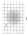
- FIG 2 illustrated is a typical first pass on a 6 millimeter treatment zone using a 2 millimeter spot on the eye formed by the first diaphragm opening 1002.
- This is illustrative only, and preferably would be a pattern such as that illustrated in Fig. 2A.
- International Publication No. WO 96/11655 International Application No. PCT/EP95/04028, particularly Figs. 19-28 and the related discussion.
- a basic ablation profile is achieved.
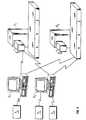
- the dual spot size system according to the invention is used in conjunction with a topography system.
- a topography system T1 is used in conjunction with other visual acuity techniques to determine the degree and type of correction a patient needs, such as for myopia, hyperopia, or astigmatism.
- a basic treatment pattern is developed by a computer C1 based on the topographic data provided by the topography system T1 and implemented on an excimer laser eye surgery system E1.
- Second and third topography systems T2 and T3, respectively, are coupled to a computer system C2, which is coupled to an excimer laser eye surgery system E2 and also to eye surgery system E1.
- Computer C1 is also coupled to eye surgery system E2, and all of these components together provide a distributed topography, treatment creation and excimer laser system. See International Publication No. WO 97/46183 (International Application No. PCT/EP97/02721) for more information on distributed excimer laser surgery systems.
- the basic treatment pattern may need refinement because of irregularities in the profile of the patient's eye. Therefore, the doctor could compare the calculated results of the basic treatment pattern using the large spot size with the desired topography. Then, simulating the use of the smaller spot size, the doctor could use free hand techniques to provide appropriate shots within the treatment pattern to correct for the remaining irregularity, resulting, for example, in the treatment of Figure 3. This detailed correction could either be provided with computer assistance suggesting a sequence of smaller shots to fill in the irregular area, or perhaps using a cursor, mouse, or other pointing device to allow the doctor to "paint" in the area to be treated. The computer system would then calculate the theoretical result of ablating an eye with the topography determined by the topography system T1, and hopefully this would be within an acceptable error limit. If not, the doctor could provide further refinements using the smaller spot size.
- a large, fixed spot size is used to provide for basic correction of hyperopia, myopia, or astigmatism. Then, any remaining irregularities are removed using the smaller fixed spot size. Further, the large spot size pattern can be automatically calculated, with the small spot size being manually “painted in” by the physician, or could be automatically calculated under the physician's supervision.
- the large fixed spot size uses a large, fixed spot size scanning technique, and the small fixed spot size is provided with small overlapping shots.
Abstract
Description
- The invention relates to an apparatus and technique for surgically modifying the curvature of the eye cornea and a method of controlling the apparatus, and more particularly to an apparatus for immediately correcting a variety of corneal defects using dual, fixed spot sizes.
- Excimer laser eye surgery systems are often used for correcting vision. From eye glasses to radial keratotomy, ophthalmic surgery has now progressed to a point where the surface of the eye is actually reshaped using cold light laser ablation provided by excimer lasers, typically argon fluoride lasers operating at around 193 nanometers. These lasers are even used to reshape the stromal tissue underneath the surface of the eye in a laser in situ keratomileusis technique patented by Gholam Peyman in U.S. Patent No. 4,840,175.
- These techniques start with the uncorrected profile of the eye, and then ablate the eye using various small or large beam techniques, or aperture techniques, to reprofile the surface into a desired, corrected profile. The amount of correction is determined by a variety of methods, but for myopia, for example, given the starting curvature of the eye and the amount of dioptric correction needed, equations are well known which specify the amount of tissue that must be removed from each point on the surface of the eye. These equations are found, for example, in PCT Patent Application Serial No. PCT/EP93/02667. Similar equations are known for the amount of tissue necessary for removal to correct for hyperopia and astigmatism.
- Before relying on these equations, however, the actual curvature of the eye must be determined. This is done using a number of techniques. The patient's visual acuity can be determined through eye exams. The actual shape of the surface of the eye can be determined, for example, using a topography system. These topography systems can be either manual or computerized, and the latter can provide a point-by-point representation of the curvature of the eye, for example, in the form of an axial curvature, the instantaneous or true local curvature, or the absolute height.
- Typically, based on these curvatures and a patient's visual acuity, a doctor programs into an excimer laser surgery system an amount of positive or negative dioptric correction (depending on whether the correction is for hyperopia or myopia) and an angle of the cylinder of astigmatism, if any, along with the amount of dioptric correction necessary for the astigmatism. Software within the excimer system itself then calculates a shot pattern suitable for achieving the objective, and that pattern is executed on the surface of the patient's eye.
- International Publication No. WO 97/46183 (International Application No. PCT/EP97/02721) discloses a distributed system for controlling excimer laser eye surgery. A topography system, a computer system, and an excimer laser eye surgery system are provided, with the topography system providing profile data to the computer system, and the computer system calculating and providing an ablation shot pattern to the excimer laser eye surgery system. The computer system and the excimer laser eye surgery system can be located remotely. The excimer laser eye surgery system can receive data from more than one computer system and from more than one topography system for better utilization of resources.
- A number of systems have been developed to reshape the cornea, using a variety of techniques such as variable sized circular apertures to correct for myopia, variable sized ring shaped apertures to correct for hyperopia, and variable sized slit shaped apertures to correct for astigmatism. These techniques collectively came to be known as photorefractive keratectomy. It has been recognized that using such apertures to correct for myopia, for example, a series of excimer laser shots using progressively smaller spot sizes could ablate away a portion of the cornea to effectively build a "corrective lens" into the cornea.
- These techniques are discussed, for example, in U.S. Patent No. 4,973,330, entitled "Surgical Apparatus for Modifying the Curvature of the Eye Cornea," issued November 27, 1990, and in U.S. Patent No. 4,729,372, entitled "Apparatus for Performing Ophthalmic Laser Surgery," issued March 8, 1988. Those skilled in the art of laser ophthalmological surgery have extensively developed the required exposure patterns using these variable size apertures to provide an appropriate amount of correction to various degrees of myopia, hyperopia, and astigmatism, and a combination of these conditions. These multiple aperture systems tend to be complicated and inflexible. A number of aperture wheels or masks are required, and only standard forms of correction for myopia and hyperopia with circular symmetry and astigmatism with cylindrical symmetry are provided.
- An apparatus for ablating tissue from the eye is shown in U.S. Patent No. 4,973,330, referenced above. This apparatus includes an excimer laser, the laser beam of which impinges on the cornea, with the axis of the laser beam coinciding with the optical axis of the eye. Furthermore, a field stop limits the area of the laser spot on the cornea illuminated by the laser beam, and the size of this field stop is set in a temporarily variable manner according to the profile of the area to be removed so that the thickness of the area to be removed is a function of the distance from the optical axis of the eye.
- The system described in U.S. Patent No. 4,973,330 permits in this way setting the "laser energy deposited" on the cornea as the function of the distance from the optical axis of the eye, but only under the condition that the distribution of energy (i.e., the power of the laser beam spot) is homogeneous, or at least axially symmetrical. This, however, is a condition that excimer lasers in particular do not always fulfill. Inhomogeneous power distribution results in non-axially symmetrical removal. Moreover, the system described in U.S. Patent No. 4,973,330 only permits the correction of spherical aberrations, not astigmatism.
- An apparatus based on the same fundamental idea is known from U. S. Patent No. 4,994,058, entitled "Surface Shaping Using Lasers", issued February 19, 1991. That apparatus employs a "destructible field stop mask" instead of a field stop having a temporarily variable aperture.
- Another class of apparatus for shaping the cornea by means of removing tissue is known from the various L'Esperance patents. These include U.S. Patent Nos. 4,665,913; 4,669,466; 4,718,418; 4,721,379; 4,729,372; 4,732,148; 4,770,172; 4,773,414; and 4,798,204. In that apparatus, a laser beam with a small focus spot is moved by a two-dimensional scanning system over the area to be removed. This apparatus, which operates as a "scanner," has the advantage that it can generate any two-dimensional profile of deposited energy "over the area to be removed."
- International Publication No. WO 96/11655 (International Application No. PCT/EP95/04028) discloses an apparatus and method for controlling an apparatus for removing tissue from the eye, performing various types of corrections using a relatively large beam, but oscillating or dithering to prevent reinforcing ridges from being formed during the tissue removal process. Various types of correction, such as hyperopia and astigmatism correction, are performed using a large beam that is scanned over the area to be ablated using overlapping shots.
- Using an infrared fluorescent dye to dye the epithelium, the epithelium in the area to be treated is removed while observing the fluorescent patterns from the epithelium. Once a certain area is no longer fluorescent after laser shots, smaller shots are then applied, selectively removing the epithelium from the remaining regions. Using two astigmatism correcting ablation patterns intersecting at an angle, a lens is created capable of correcting for myopia, hyperopia, and astigmatism. Overlapping shots, using a relatively large fixed spot size, provide for reduced thermal heating, ridgeless treatment patterns, reduced shot count and simplified equipment. Thus, this reference illustrates a single fixed spot size system using a large fixed spot in an overlapping pattern to correct vision.
- With the various advances, excimer laser eye surgery systems implement a variety of techniques to re-profile the surface of the eye. The use of large spot sizes reduces treatment time and increases the amount of tissue removed per shot, but small spot sizes provide for finer resolution of correction. A technique and apparatus with the advantages of both would be greatly desirable.
- An apparatus according to the first part of
claim 1 is known from WO-A-94/07447. - According to the invention, a dual mode excimer laser eye surgery system is provided. In this system, the eye is first treated for primary corneal defects, such as myopia, hyperopia, and astigmatism, using a large, fixed spot size. Then, a small fixed spot size is used to remove remaining irregularities. The large size allows for faster treatment. The small size provides for more precision in the treatment of irregular topographies.
- Further, such a system is preferably implemented in a distributed topography environment. For example, a treatment pattern using the large, fixed spot size is provided to doctors based on visual acuity data, such as the degree of dioptric correction needed. Then, the effect of this treatment is overlaid on a computer against the patient's actual eye topography. The doctor then uses the small fixed spot size to remove any remaining irregularities yielding a preferred treatment pattern. This combined treatment pattern is then distributed to an excimer laser eye surgery system that performs the large spot size ablation and then the small spot size ablation.
- Fig. 1 is a simplified diagram illustrating a typical excimer laser eye surgery system.
- Fig. 1A illustrates a dual fixed diaphragm that would replace the variable diaphragm in the excimer laser eye surgery system of Fig. 1, wherein a large spot size diaphragm opening is positioned in the path of a laser beam, according to the present invention.
- Fig. 1B illustrates the dual fixed diaphragm of Fig. 1A, wherein a small spot size diaphragm opening is positioned in the path of the laser beam, according to the present invention.
- Fig. 2 is an illustration of portion of a first pass for correcting vision using the large fixed spot size.
- Fig. 2A is an illustration of a typical shot pattern.
- Fig. 3 is an illustration of the second pass for correcting vision using a smaller fixed spot size.
- Fig. 4 is a block diagram illustrating the interrelationship of multiple components in an excimer laser eye surgery system.
-
- Fig. 1 shows a typical
eye surgery system 10. Anexcimer laser 20 provides apulsed beam 22 to abeam homogenizer 24 after reflection fromoptics 26. Ashutter 28 is also provided to block transmission of thepulsed beam 22 to thebeam homogenizer 24. Theexcimer laser 20 is a typical excimer laser as is well known in the art. It preferably provides a 193 nm wavelength beam with a maximum pulse energy of 400 mJ/pulse. Theexcimer laser 20 preferably provides maximum power at the treatment site of 1 W, with a pulse frequency of 10 Hz and a pulse length of 18 ns. By way of example, the wavelength of the light from the laser is preferably less than 400 nm, as that provides the desired ablating action with reduced thermal heating. Further, other pulse energies can be provided, such as all the way down to 200 mJ/pulse, with typical repetition rates of 60 to 100 pulses per second with a typical pulse length of 10 to 30 ns. - The
beam homogenizer 24 preferably includes standard homogenization and focusing hardware, which can be based both on optical mixing of the beam and on rotation of the beam. From thebeam homogenizer 24, thepulsed beam 22 is then reflected off ofoptics 30, which also passes a red pilot laser beam from apilot laser 32. Thispilot laser 32 is preferably a 633 nm helium neon laser of less than 1 mW of power. The red pilot beam from thepilot laser 32 can also be blocked by ashutter 34. Thepilot laser 32 is aligned so that its optical pathway coincides with thepulsed beam 22. Thepilot laser 32 provides the functions of centering thebeam 22 on the axis of treatment of theeye 44 and also provides for focusing on theeye 44. Further, it can provide an optical fixation point for the patient, although a different laser or light source could also be provided for that purpose. - From the
optics 30, the pulsed beam 20 (now also co-aligned with the beam from the pilot laser 32) then passes through anadjustable diaphragm 36, which allows the beam size to be adjusted before it enters the final optics. After thediaphragm 36, aspot mode lens 38, when in place, provides further concentration of thebeam 22, allowing spot ablation of certain defects in the eye by a physician performing therapeutic rather than refractive surgery. Thespot mode lens 38 is thus moved into and out of place depending on whether therapeutic or refractive treatment is desired. - Following the
spot mode lens 38, a focusinglens 40 directs thebeam 22 onto thescanning mirror 42, which then reflects thebeam 22 onto a patient'seye 44. Note that the portion of thebeam 22 from thepilot laser 32 is used for both adjusting the distance of theeye 44 from the entireeye surgery system 10 and for providing centering, as will be discussed below. The focusinglens 40 focuses light such that when theeye 44 is at the optimal distance, thebeam 22 is properly focused onto theeye 44. - These various lenses and mirrors thus combine to form an optical system providing an excimer beam to the cornea. The optical system creates a laser spot on the cornea, and the spot size is adjustable, along with its location. It will be readily appreciated that a wide variety of different systems could be used to optically provide such a beam. For example, a lens could be used to adjust the spot size rather than an aperture, and instead of a scanning mirror, the patient or the patient's
eye 44 could be physically moved to provide for shots at different locations on theeye 44. - Also provided in the system is a focusing
laser 46, whose beam can also be blocked by ashutter 48. The focusinglaser 46 is preferably a green helium neon laser providing a beam of a wavelength of 535 nm and less than 1 mW of power. The beam from the focusinglaser 46 travels throughoptics 50 and impinges on theeye 44 at an angle. The distance of theeye 44 from theeye surgery system 10 is adjusted such that both the beam from thepilot laser 32 and the beam from the focusinglaser 46 impinge on the surface of theeye 44 at the same point. - Further provided is an
optional fixation mask 52, which is well known in the art and is used to stabilize theeye 44 during surgery. It can include debris removal components, and is typically attached to theeye 44 through either a vacuum suction ring or through hooks. A cleangas purge unit 54 ensures that the optics and the beams in the system are free from any floating debris. - A
microscope 56 is provided for the physician to observe progress during ablation of the surface of theeye 44. Themicroscope 56 is preferably a ZEISS OPMI "PLUS" part No. 3033119910, with magnifications of 3.4, 5.6 and 9.0 times. Field illumination is provided by a cold light source not shown, which is preferably the Schott KL 1500 Electronic, ZEISS part number 417075. Thismicroscope 56 focuses through thescanning mirror 42 and also focuses through asplitting mirror 58. The splitting mirror further provides a view of theeye 44 to aninfrared video unit 60, which is used for the epithelial ablation discussed below. Theinfrared video unit 60 preferably provides an image output to a capturingvideo screen 62 and to acontrol unit 64. Theinfrared video unit 60 is preferably sensitive to both infrared light and visible light. - The
control unit 64, which is typically a high performance computer compatible with an IBM PC by International Business Machines Corp., further preferably controls all components of theeye surgery system 10, including theshutters diaphragm 36, thespot mode lens 38, and thescanning mirror 42. - With reference to Figs. 1A and 1B, a typical dual diaphragm is illustrated that would be used according to the invention to implement dual fixed spot size excimer laser surgery. According to the invention, for example, one would replace the variable diaphragm 36 (Fig. 1) with the dual fixed diaphragm illustrated in Figs. 1A and 1B. Specifically, a
dual diaphragm plate 1000 is slidable to the left or to the right. It is placed in a path of laser beam 22 (Fig. 1) and shifted between its two positions to provide two different spot sizes of the beam. In Fig. 1A, thediaphragm plate 1000 is in a first position in which a large spotsized diaphragm opening 1002 is positioned in the path of thelaser beam 22. As is seen, thislarge diaphragm opening 1002 passes acircular beam 1004 of a first size. Aremainder 1006 of thebeam 22 is reflected into alaser dump 1008 where it is absorbed. - When it is desired to employ the second, smaller spot size, as illustrated in Fig. 1B, the
diaphragm plate 1000 is shifted into a second position. In this position, asmaller diaphragm opening 1010 passes asmaller laser spot 1012. Again, aremainder 1014 of thebeam 22 is reflected into thelaser dump 1008. - It will be appreciated that the actual size of the spots of the
diaphragm openings eye 44. However, it will be appreciated that these two spot sizes will provide for two different sizes of beam impingement on theeye 44. Preferably, thediaphragm opening 1002 is of a size to form an approximately two millimeter diameter spot size on the eye, whereas theopening 1010 is of a size appropriate to form a one millimeter diameter spot size. Other sizes can be used, preferably with the first size large enough to fairly quickly perform a basic ablation pattern, with the second size being relatively small, small enough to provide precise correction of any remaining defects. - Turning to Figure 2, illustrated is a typical first pass on a 6 millimeter treatment zone using a 2 millimeter spot on the eye formed by the
first diaphragm opening 1002. This is illustrative only, and preferably would be a pattern such as that illustrated in Fig. 2A. For additional patterns and methods of operation, see International Publication No. WO 96/11655 (International Application No. PCT/EP95/04028), particularly Figs. 19-28 and the related discussion. Using a large, 2 millimeter spot, a basic ablation profile is achieved. - Then turning to Figure 3, assume that after the basic ablation performed in Figure 2, a remaining area 1020 is irregular compared to a desired eye profile. Then, the smaller spot formed by the
opening 1010 is used to create a plurality ofshots 1022 that "smooth" the remaining irregularity. - Preferably, the dual spot size system according to the invention is used in conjunction with a topography system. With reference to Fig. 4, for example, a topography system T1 is used in conjunction with other visual acuity techniques to determine the degree and type of correction a patient needs, such as for myopia, hyperopia, or astigmatism. A basic treatment pattern is developed by a computer C1 based on the topographic data provided by the topography system T1 and implemented on an excimer laser eye surgery system E1. Second and third topography systems T2 and T3, respectively, are coupled to a computer system C2, which is coupled to an excimer laser eye surgery system E2 and also to eye surgery system E1. Computer C1 is also coupled to eye surgery system E2, and all of these components together provide a distributed topography, treatment creation and excimer laser system. See International Publication No. WO 97/46183 (International Application No. PCT/EP97/02721) for more information on distributed excimer laser surgery systems.
- The basic treatment pattern, however, may need refinement because of irregularities in the profile of the patient's eye. Therefore, the doctor could compare the calculated results of the basic treatment pattern using the large spot size with the desired topography. Then, simulating the use of the smaller spot size, the doctor could use free hand techniques to provide appropriate shots within the treatment pattern to correct for the remaining irregularity, resulting, for example, in the treatment of Figure 3. This detailed correction could either be provided with computer assistance suggesting a sequence of smaller shots to fill in the irregular area, or perhaps using a cursor, mouse, or other pointing device to allow the doctor to "paint" in the area to be treated. The computer system would then calculate the theoretical result of ablating an eye with the topography determined by the topography system T1, and hopefully this would be within an acceptable error limit. If not, the doctor could provide further refinements using the smaller spot size.
- Therefore, using the techniques according to the invention, a large, fixed spot size is used to provide for basic correction of hyperopia, myopia, or astigmatism. Then, any remaining irregularities are removed using the smaller fixed spot size. Further, the large spot size pattern can be automatically calculated, with the small spot size being manually "painted in" by the physician, or could be automatically calculated under the physician's supervision.
- It will be appreciated that a variety of techniques can be used to provide the two spot sizes. For example, instead of using the sliding dual diaphragm, a variable diaphragm as in the
diaphragm 36 of Figure 1 could be used, but simply programmed to only assume two different sizes. One skilled in the art will appreciate the variety of techniques to form two discrete sizes. - Preferably, the large fixed spot size uses a large, fixed spot size scanning technique, and the small fixed spot size is provided with small overlapping shots.
- The foregoing disclosure and description of the invention are illustrative and explanatory thereof, and various changes in the size, shape, materials, components, circuit elements, and optical components, as well as in the details of the illustrated system and construction and method of operation may be made without departing from the spirit of the invention.
Claims (13)
- An apparatus (10) for shaping the cornea by removing tissue from a region of the cornea that has an area to be subject to ablation to a desired treatment pattern, comprising: a laser (20) that emits a laser beam (22) having a suitable wavelength, an optical system (40, 42) coupled to said laser that receives the laser beam and delivers the laser beam onto the region of the cornea, said optical system controllably deflecting the laser beam to different points on the region of the cornea,
characterized by
dual spot optics (36, 38) coupled to the optical system and restricting the optical system to provide the laser beam only at a larger, single fixed spot size on the region of the cornea and a smaller, single fixed spot size on the region of the cornea, wherein the larger fixed spot size on the region of the cornea is a relatively large fraction of the area of the region of the cornea to be subject to ablation, and the smaller fixed spot size on the region of the cornea is relatively small compared to the larger fixed spot size; and
a controller (64) for directing the optical system and for directing said laser to fire the laser beam and the optical system to image the laser beam in a series of shots at a plurality of different points on the region of the cornea only at the larger fixed spot size and the smaller fixed spot size, which together cummulatively create the desired treatment pattern. - The apparatus of claim 1, wherein the dual spot optics includes a dual fixed diaphragm (36, 1000).
- The apparatus of claim 2, wherein the dual fixed diaphragm is placed in the path (22) of the laser beam.
- The apparatus of claim 2, wherein the dual fixed diaphragm slides between a first position and a second position.
- The apparatus of claim 2, wherein the dual fixed diaphragm has a first opening (1002) and second opening (1010) that is smaller than the first opening.
- The apparatus of claim 1, wherein the dual spot optics includes a dual fixed diaphragm placed in the path of the laser beam, the dual fixed diaphragm sliding between a first position and a second position and having a first opening and a second opening smaller than the first opening, the laser beam passing through the first opening when the dual fixed diaphragm is in the first position and through the second opening when the dual fixed diaphragm is in the second position.
- The apparatus of claim 1, wherein the dual spot optics - is a variable diaphragm (36) that is programmably controlled to only assume two different sizes.
- The apparatus according to any of claims 1 to 7, further characterized by
a topography system (T1, T2, T3) that provides profile data corresponding to the profile of the cornea of a patient;
a computer system (C1, C2) with a program for developing an initial ablation shot pattern and a refined shot pattern which together form an overall desired shot pattern from the profile data;
a first data link between said topography system and said computer system for transmission of the profile data from said topography system to said computer system;
and
a second data link between said computer system and said laser eye surgery apparatus for transmission of the initial ablation shot pattern and the refined shot pattern from said computer system to said laser eye surgery apparatus, wherein said laser eye surgery apparatus is located in a physically different vicinity than said computer system. - The apparatus of any of claims 1 to 8, wherein the laser is an excimer laser.
- The apparatus of any of claims 1 to 9, wherein the larger fixed spot size laser beam has a diameter of at least 2.0mm.
- The apparatus of any of claims 1 to 10, wherein the smaller fixed spot size laser beam has a diameter of not more than 1.0 mm.
- The apparatus of any of claims 1 to 11, wherein the dual spot optics is a lens.
- The apparatus of any of claims 1 to 12, wherein the smaller fixed spot size series of shots are overlapping shots.
Applications Claiming Priority (3)
| Application Number | Priority Date | Filing Date | Title |
|---|---|---|---|
| US4490897P | 1997-04-25 | 1997-04-25 | |
| US44908P | 1997-04-25 | ||
| PCT/EP1998/002428 WO1998048746A1 (en) | 1997-04-25 | 1998-04-24 | Dual mode ophthalmic laser ablation |
Publications (2)
| Publication Number | Publication Date |
|---|---|
| EP1011563A1 EP1011563A1 (en) | 2000-06-28 |
| EP1011563B1 true EP1011563B1 (en) | 2005-11-09 |
Family
ID=21934981
Family Applications (1)
| Application Number | Title | Priority Date | Filing Date |
|---|---|---|---|
| EP98922772A Expired - Lifetime EP1011563B1 (en) | 1997-04-25 | 1998-04-24 | Dual mode ophthalmic laser ablation |
Country Status (10)
| Country | Link |
|---|---|
| EP (1) | EP1011563B1 (en) |
| JP (1) | JP2001522279A (en) |
| CN (1) | CN1211055C (en) |
| AU (1) | AU735854B2 (en) |
| BR (1) | BR9808977A (en) |
| CA (1) | CA2287284C (en) |
| DE (1) | DE69832289T2 (en) |
| ES (1) | ES2251082T3 (en) |
| HK (1) | HK1026359A1 (en) |
| WO (1) | WO1998048746A1 (en) |
Families Citing this family (19)
| Publication number | Priority date | Publication date | Assignee | Title |
|---|---|---|---|---|
| US6129722A (en) | 1999-03-10 | 2000-10-10 | Ruiz; Luis Antonio | Interactive corrective eye surgery system with topography and laser system interface |
| US6373571B1 (en) * | 1999-03-11 | 2002-04-16 | Intralase Corp. | Disposable contact lens for use with an ophthalmic laser system |
| DE60025387T2 (en) | 1999-10-21 | 2006-07-06 | Technolas Gmbh Ophthalmologische Systeme | METHOD AND DEVICE FOR OPHTHALMIC, REFRACTIVE CORRECTION |
| CA2388014C (en) * | 1999-10-21 | 2013-04-16 | Technolas Gmbh Ophthalmologische Systeme | Multi-step laser correction of ophthalmic refractive errors |
| CN100563607C (en) * | 2003-04-11 | 2009-12-02 | 泰克诺拉斯眼科系统有限公司 | Method and system about the vision correction processing plan |
| JP4724663B2 (en) * | 2003-09-30 | 2011-07-13 | パナソニック株式会社 | Mold for optical parts |
| DE102005046130A1 (en) | 2005-09-27 | 2007-03-29 | Bausch & Lomb Inc. | Excimer laser-eye surgical system, has eye tracing device sending instruction signal to laser device via bidirectional bus to fire shot, when preset position data is same as initial position data of scanning device for shot |
| EP1862154B1 (en) * | 2006-05-31 | 2011-03-23 | Ziemer Holding AG | Ophthalmologic Device |
| DE102006036085A1 (en) | 2006-08-02 | 2008-02-07 | Bausch & Lomb Incorporated | Method and apparatus for calculating a laser shot file for use in an excimer laser |
| AT505357B1 (en) * | 2007-06-13 | 2009-04-15 | Lechthaler Andreas | DEVICE FOR IRRADIATING AN OBJECT, IN PARTICULAR THE HUMAN SKIN, WITH UV LIGHT |
| DE102008028509A1 (en) | 2008-06-16 | 2009-12-24 | Technolas Gmbh Ophthalmologische Systeme | Treatment pattern monitoring device |
| KR101312706B1 (en) | 2008-06-30 | 2013-10-01 | 웨이브라이트 게엠베하 | Device for ophthalmologic, particularly refractive, laser surgery |
| DE102008035995A1 (en) | 2008-08-01 | 2010-02-04 | Technolas Perfect Vision Gmbh | Combination of excimer laser ablation and femtosecond laser technique |
| DE102008053827A1 (en) | 2008-10-30 | 2010-05-12 | Technolas Perfect Vision Gmbh | Apparatus and method for providing a laser shot file |
| MX2011012594A (en) * | 2009-05-26 | 2012-04-02 | Wavelight Gmbh | System for laser surgical ophthalmology. |
| JP6236882B2 (en) * | 2013-06-03 | 2017-11-29 | 株式会社ニデック | Laser therapy device |
| EP3019108A1 (en) * | 2013-07-11 | 2016-05-18 | Koninklijke Philips N.V. | Device and method for non-invasive treatment of skin using laser light |
| DE102014105943A1 (en) * | 2014-04-28 | 2015-10-29 | Vossamed Gmbh & Co. Kg | Device for creating cuts or perforations on the eye |
| JP6657591B2 (en) * | 2015-05-01 | 2020-03-04 | 株式会社ニデック | Ophthalmic laser delivery and ophthalmic laser treatment device |
Citations (2)
| Publication number | Priority date | Publication date | Assignee | Title |
|---|---|---|---|---|
| DE4232915A1 (en) * | 1992-10-01 | 1994-04-07 | Hohla Kristian | Device for shaping the cornea by removing tissue |
| WO1996011655A1 (en) * | 1994-10-14 | 1996-04-25 | Chiron/Technolas Gmbh Ophthalmologische Systeme | Excimer laser system for correction of vision |
Family Cites Families (15)
| Publication number | Priority date | Publication date | Assignee | Title |
|---|---|---|---|---|
| US4718418A (en) | 1983-11-17 | 1988-01-12 | Lri L.P. | Apparatus for ophthalmological surgery |
| US4770172A (en) | 1983-11-17 | 1988-09-13 | Lri L.P. | Method of laser-sculpture of the optically used portion of the cornea |
| US4732148A (en) | 1983-11-17 | 1988-03-22 | Lri L.P. | Method for performing ophthalmic laser surgery |
| US4665913A (en) | 1983-11-17 | 1987-05-19 | Lri L.P. | Method for ophthalmological surgery |
| US4729372A (en) | 1983-11-17 | 1988-03-08 | Lri L.P. | Apparatus for performing ophthalmic laser surgery |
| US4773414A (en) | 1983-11-17 | 1988-09-27 | Lri L.P. | Method of laser-sculpture of the optically used portion of the cornea |
| US4669466A (en) | 1985-01-16 | 1987-06-02 | Lri L.P. | Method and apparatus for analysis and correction of abnormal refractive errors of the eye |
| FR2576780B1 (en) | 1985-02-04 | 1991-06-14 | Azema Alain | APPARATUS FOR CHANGING THE CURVATURE OF THE EYE CORNEA OVER THE WHOLE PUPILLARY SURFACE BY PHOTOCHEMICAL ABLATION OF THE SAME |
| GB8606821D0 (en) | 1986-03-19 | 1986-04-23 | Pa Consulting Services | Corneal reprofiling |
| US4840175A (en) | 1986-12-24 | 1989-06-20 | Peyman Gholam A | Method for modifying corneal curvature |
| CA2021696A1 (en) * | 1989-08-11 | 1991-02-12 | David F. Muller | Laser reprofiling system employing a light restricting mask |
| DE4103493C1 (en) * | 1991-02-06 | 1992-07-09 | Aesculap Ag, 7200 Tuttlingen, De | |
| US5217453A (en) * | 1991-03-18 | 1993-06-08 | Wilk Peter J | Automated surgical system and apparatus |
| WO1996021407A1 (en) * | 1995-01-11 | 1996-07-18 | Summit Technology, Inc. | Integrated laser reprofiling systems |
| US5891132A (en) | 1996-05-30 | 1999-04-06 | Chiron Technolas Gmbh Opthalmologische Systeme | Distributed excimer laser surgery system |
-
1998
- 1998-04-24 WO PCT/EP1998/002428 patent/WO1998048746A1/en active IP Right Grant
- 1998-04-24 CA CA2287284A patent/CA2287284C/en not_active Expired - Lifetime
- 1998-04-24 DE DE69832289T patent/DE69832289T2/en not_active Expired - Lifetime
- 1998-04-24 CN CNB988045001A patent/CN1211055C/en not_active Expired - Lifetime
- 1998-04-24 BR BR9808977-3A patent/BR9808977A/en not_active IP Right Cessation
- 1998-04-24 JP JP54658598A patent/JP2001522279A/en active Pending
- 1998-04-24 ES ES98922772T patent/ES2251082T3/en not_active Expired - Lifetime
- 1998-04-24 AU AU75288/98A patent/AU735854B2/en not_active Expired
- 1998-04-24 EP EP98922772A patent/EP1011563B1/en not_active Expired - Lifetime
-
2000
- 2000-09-12 HK HK00105735A patent/HK1026359A1/en not_active IP Right Cessation
Patent Citations (3)
| Publication number | Priority date | Publication date | Assignee | Title |
|---|---|---|---|---|
| DE4232915A1 (en) * | 1992-10-01 | 1994-04-07 | Hohla Kristian | Device for shaping the cornea by removing tissue |
| WO1994007447A2 (en) * | 1992-10-01 | 1994-04-14 | Kristian Hohla | Apparatus for modifying the surface of the eye through large beam laser polishing and method of controlling the apparatus |
| WO1996011655A1 (en) * | 1994-10-14 | 1996-04-25 | Chiron/Technolas Gmbh Ophthalmologische Systeme | Excimer laser system for correction of vision |
Also Published As
| Publication number | Publication date |
|---|---|
| CA2287284A1 (en) | 1998-11-05 |
| HK1026359A1 (en) | 2000-12-15 |
| JP2001522279A (en) | 2001-11-13 |
| DE69832289T2 (en) | 2006-08-10 |
| CN1211055C (en) | 2005-07-20 |
| BR9808977A (en) | 2000-08-01 |
| EP1011563A1 (en) | 2000-06-28 |
| WO1998048746A1 (en) | 1998-11-05 |
| AU735854B2 (en) | 2001-07-19 |
| AU7528898A (en) | 1998-11-24 |
| ES2251082T3 (en) | 2006-04-16 |
| CA2287284C (en) | 2010-06-15 |
| DE69832289D1 (en) | 2005-12-15 |
| CN1253487A (en) | 2000-05-17 |
Similar Documents
| Publication | Publication Date | Title |
|---|---|---|
| EP1011563B1 (en) | Dual mode ophthalmic laser ablation | |
| EP0662810B1 (en) | Apparatus for shaping the cornea by large beam laser polishing | |
| CA2073802C (en) | Method and apparatus for combined cylindrical and spherical eye corrections | |
| JP3615487B2 (en) | Offset ablation profile for treatment of irregular astigmatism | |
| JP4516756B2 (en) | Blend region and transition region for cornea removal | |
| EP0402250B1 (en) | Noncontact laser microsurgical apparatus | |
| AU2005277499B8 (en) | Apparatus and method for correction of aberrations in laser system optics | |
| JP2000513611A (en) | Correction of astigmatic myopia or hyperopia by laser ablation | |
| US5906608A (en) | Ablation apparatus | |
| JP2000279440A (en) | Cornea operating device | |
| WO1995027452A1 (en) | Correction of vision through overlapping cylindrical lenses | |
| AU671668C (en) | Apparatus for modifying the surface of the eye through large beam laser polishing and method of controlling the apparatus |
Legal Events
| Date | Code | Title | Description |
|---|---|---|---|
| PUAI | Public reference made under article 153(3) epc to a published international application that has entered the european phase |
Free format text: ORIGINAL CODE: 0009012 |
|
| 17P | Request for examination filed |
Effective date: 19991119 |
|
| AK | Designated contracting states |
Kind code of ref document: A1 Designated state(s): DE ES FR GB IT |
|
| 17Q | First examination report despatched |
Effective date: 20031126 |
|
| RAP1 | Party data changed (applicant data changed or rights of an application transferred) |
Owner name: TECHNOLAS GMBH OPHTHALMOLOGISCHE SYSTEME |
|
| GRAP | Despatch of communication of intention to grant a patent |
Free format text: ORIGINAL CODE: EPIDOSNIGR1 |
|
| GRAS | Grant fee paid |
Free format text: ORIGINAL CODE: EPIDOSNIGR3 |
|
| GRAA | (expected) grant |
Free format text: ORIGINAL CODE: 0009210 |
|
| AK | Designated contracting states |
Kind code of ref document: B1 Designated state(s): DE ES FR GB IT |
|
| REG | Reference to a national code |
Ref country code: GB Ref legal event code: FG4D |
|
| REF | Corresponds to: |
Ref document number: 69832289 Country of ref document: DE Date of ref document: 20051215 Kind code of ref document: P |
|
| REG | Reference to a national code |
Ref country code: ES Ref legal event code: FG2A Ref document number: 2251082 Country of ref document: ES Kind code of ref document: T3 |
|
| ET | Fr: translation filed | ||
| PLBE | No opposition filed within time limit |
Free format text: ORIGINAL CODE: 0009261 |
|
| STAA | Information on the status of an ep patent application or granted ep patent |
Free format text: STATUS: NO OPPOSITION FILED WITHIN TIME LIMIT |
|
| 26N | No opposition filed |
Effective date: 20060810 |
|
| REG | Reference to a national code |
Ref country code: DE Ref legal event code: R081 Ref document number: 69832289 Country of ref document: DE Owner name: TECHNOLAS PERFECT VISION GMBH, DE Free format text: FORMER OWNER: TECHNOLAS GMBH OPHTHALMOLOGISCHE SYSTEME, 85622 FELDKIRCHEN, DE Effective date: 20110415 |
|
| REG | Reference to a national code |
Ref country code: FR Ref legal event code: PLFP Year of fee payment: 19 |
|
| REG | Reference to a national code |
Ref country code: FR Ref legal event code: PLFP Year of fee payment: 20 |
|
| PGFP | Annual fee paid to national office [announced via postgrant information from national office to epo] |
Ref country code: FR Payment date: 20170322 Year of fee payment: 20 |
|
| PGFP | Annual fee paid to national office [announced via postgrant information from national office to epo] |
Ref country code: GB Payment date: 20170328 Year of fee payment: 20 |
|
| PGFP | Annual fee paid to national office [announced via postgrant information from national office to epo] |
Ref country code: DE Payment date: 20170428 Year of fee payment: 20 |
|
| PGFP | Annual fee paid to national office [announced via postgrant information from national office to epo] |
Ref country code: ES Payment date: 20170330 Year of fee payment: 20 Ref country code: IT Payment date: 20170414 Year of fee payment: 20 |
|
| REG | Reference to a national code |
Ref country code: DE Ref legal event code: R071 Ref document number: 69832289 Country of ref document: DE |
|
| REG | Reference to a national code |
Ref country code: GB Ref legal event code: PE20 Expiry date: 20180423 |
|
| PG25 | Lapsed in a contracting state [announced via postgrant information from national office to epo] |
Ref country code: GB Free format text: LAPSE BECAUSE OF EXPIRATION OF PROTECTION Effective date: 20180423 |
|
| REG | Reference to a national code |
Ref country code: ES Ref legal event code: FD2A Effective date: 20201106 |
|
| PG25 | Lapsed in a contracting state [announced via postgrant information from national office to epo] |
Ref country code: ES Free format text: LAPSE BECAUSE OF EXPIRATION OF PROTECTION Effective date: 20180425 |