EP1011263A2 - A method of color correction using multi-level halftoning - Google Patents
A method of color correction using multi-level halftoning Download PDFInfo
- Publication number
- EP1011263A2 EP1011263A2 EP99124398A EP99124398A EP1011263A2 EP 1011263 A2 EP1011263 A2 EP 1011263A2 EP 99124398 A EP99124398 A EP 99124398A EP 99124398 A EP99124398 A EP 99124398A EP 1011263 A2 EP1011263 A2 EP 1011263A2
- Authority
- EP
- European Patent Office
- Prior art keywords
- color
- input color
- nodes
- output
- input
- Prior art date
- Legal status (The legal status is an assumption and is not a legal conclusion. Google has not performed a legal analysis and makes no representation as to the accuracy of the status listed.)
- Granted
Links
Images


Classifications
-
- H—ELECTRICITY
- H04—ELECTRIC COMMUNICATION TECHNIQUE
- H04N—PICTORIAL COMMUNICATION, e.g. TELEVISION
- H04N1/00—Scanning, transmission or reproduction of documents or the like, e.g. facsimile transmission; Details thereof
- H04N1/40—Picture signal circuits
-
- H—ELECTRICITY
- H04—ELECTRIC COMMUNICATION TECHNIQUE
- H04N—PICTORIAL COMMUNICATION, e.g. TELEVISION
- H04N1/00—Scanning, transmission or reproduction of documents or the like, e.g. facsimile transmission; Details thereof
- H04N1/46—Colour picture communication systems
- H04N1/56—Processing of colour picture signals
- H04N1/60—Colour correction or control
- H04N1/6016—Conversion to subtractive colour signals
- H04N1/6019—Conversion to subtractive colour signals using look-up tables
Definitions
- Computers and other electronic equipment typically depict color in 3-D coordinates such as RGB.
- Many printers print in either three-dimensional colorant space, cyan, magenta, yellow (CMY) or four-dimensional colorant space, cyan, magenta, yellow, and black (CMYK) which correspond to the input values, e.g. RGB.
- CMY colorant space
- CMYK colorant space
- a device independent color space is used as an intermediate representation of the image.
- a common choice for such a device independent space is a luminance-chrominance space, denoted generically as LC 1 C 2 .
- the L component represents luminance or lightness
- C 1 and C 2 are the two chrominance coordinates representing red-green and yellow-blue variations, respectively.
- An example of such a space is CIELAB. Translations are then derived from input RGB to LC 1 C 2 , and from LC 1 C 2 to printer colorant space.
- a printer which has an ideal colorant behavior has a one-to-one correspondence of cyan-to-red, magenta-to-green, and yellow-to-blue. This means that when printed, the cyan colorant will only absorb red light, the magenta colorant will only absorb green light, and the yellow colorant will only absorb blue light.
- typical printer colorants deviate from this ideal behavior, and in fact absorb light in bands of the electromagnetic spectrum other than the intended absorption band. These so called unwanted absorptions lead to interactions between the colorants that result in a complex nonlinear relationship between digital values that drive the printer, and the resulting colorimetric response.
- a response, or other value, labeled as "colorimetric” refers to a measurement of the printed color, as seen by an average human observer, and represented in a device independent color coordinate system such as CIELAB. Modeling the colorimetric response across the entire range of CMYK values therefore cannot usually be achieved by a simple function, and in fact requires many parameters and measurements. The number of measurements required to characterize the printer adequately, can easily number 1,000 or more. Usually, in order to represent such a complex function at reasonable computational cost, a color correction LUT is built which approximates the mapping between colorimetric space and CMYK values. More specifically, the color correction LUT corrects for non-linearities and unwanted absorptions of colorants.
- the LUT retrieves the corresponding CMYK which, when printed and measured, will yield the requested LC 1 C 2 color, provided that this color is within the reproducible gamut of the device.
- a predefined set of CMYK digital values are sent to the printer.
- the printer prints a corresponding set of color patches.
- the calibration color patches are measured and a colorimetric LC 1 C 2 coordinate is determined for each patch, i.e. for each of the predefined CMYK values.
- Each of the measured LC 1 C 2 coordinates then, identifies a three-dimensional vector location within the three-dimensional space.
- Each LC 1 C 2 coordinate is typically represented by 8-bit values for each of the L, C 1 , and C 2 components.
- the look-up table is typically partitioned into a smaller size, such as 16x16x16 (4096) table locations, each node of which stores a CMYK value.
- CMYK values at intermediate LC 1 C 2 points are determined by some form of interpolation among the LUT nodes.
- the size of the look-up table is a compromise between the desired accuracy of the look-up table (i.e. the fidelity of the output) and the expense of storing a large number of values.
- each measured LC 1 C 2 coordinate has a corresponding known CMYK value.
- the LC 1 C 2 coordinates do not, in general, perfectly coincide with the node locations (i.e. the three dimensional intersection points) of the look-up table.
- the CMYK values placed at the nodes are estimated by some multidimensional data fitting technique such as Shepard's algorithm.
- FIGURE 1 An illustration of the operation of a look-up table is instructive.
- an input LC 1 C 2 value 10 is sent into the table 12 for conversion into a printer specific CMYK value.
- the conversion is accomplished by interpolating the known CMYK values corresponding to the nodes 14 nearest the input LC 1 C 2 coordinate location 10 . Because the color is defined in three dimensions, the interpolation is similarly done in three dimensions.
- 3-D interpolation techniques include trilinear, tetrahedral, and prism interpolation. Of these, tetrahedral interpolation is the fastest method, requiring interpolation only among 4 nodes.
- the present invention provides a new and improved method of color correction which overcomes the above-referenced problems and others.
- an improved method for lookup table based color transformations that combines multilevel halftoning with interpolation. Specifically, if the input color space to the lookup table is in luminance-chrominance coordinates, multilevel halftoning is applied to each of the chrominance coordinates to achieve coincidence with the nodes of the lookup table along these two coordinates.
- the multilevel halftoning step introduces errors at high spatial frequencies in the chrominance channels. However, these errors are not easily perceptible by the human visual system.
- 1-dimensional interpolation is performed on the luminance component to obtain the output color values.
- a method of color transforming an input color value to an output color value includes a multi-dimensional color transformation table having an arrangement of nodes. Each node defines an output color value.
- the method includes receiving the input color value and applying multilevel halftoning to a predetermined subset of the input color components to select a plurality of nodes constrained to a selected number of dimensions. Remaining others of the input color components are then used to interpolate among the selected plurality of nodes to obtain the output color value.
- an electronic imaging system including a receiver and a conversion processor are provided.
- the conversion processor includes a multi-dimensional table having a plurality of nodes each containing predefined output color data.
- a first quantizer receives a predetermined subset of the input color components and identifies nodes constrained to a selected number of dimensions.
- An interpolator calculates an output color from the predefined color data contained at the nodes identified based on remaining ones of the input color components.
- One advantage of the present invention is that the expensive 3-D interpolation is reduced to a much simpler process of halftoning and 1-D interpolation, which brings substantially savings in computation, with minimal loss in visual quality.
- Another advantage of the present invention is that the halftoning and 1-D interpolation steps require less storage and memory for precomputed quantities in the lookup table. This allows alternative grid structures to be employed for the lookup table.
- a method for reducing the cost of interpolation operations required in 3-D lookup table (LUT) based color correction is provided.
- the input color value will be described in luminance-chrominance (LC 1 C 2 ) coordinates, however, the present invention is equally applicable to other input formats with no loss of functionality.
- Multilevel halftoning is used to restrict C 1 and C 2 to a limited set of levels; namely those levels that coincide with the LUT node locations along C 1 and C 2 .
- the LUT calculation then reduces from 3-D interpolation in LC 1 C 2 to 1-D interpolation only along L. Testing shows that acceptable images can be obtained, with significant gains in computational cost as compared to the prior art 3D interpolation.
- the present invention recognizes that reducing color correction from a 3-D interpolation problem to a one-dimensional problem will significantly reduce the cost and speed of color correction.
- device independent image values are stored as luminance-chrominance coordinates, for example the CIELAB color space.
- luminance-chrominance coordinates for example the CIELAB color space.
- the human visual system is less sensitive to chrominance errors than it is to distortions in luminance at high spatial frequencies. In other words, an observer is more likely to detect small errors in luminance than in chrominance at high spatial frequencies. It is this recognition that is the basis of the present invention.
- Input color 22 comprises input color components L in , C 1in , and C 2in .
- the C 1 component is limited to a finite set of dimensions or levels 24, 25, 26, 27, 28 each coinciding with a plurality of nodes (i.e. along the C 2 and L axes).
- the C 2 component is constrained to match levels 31, 32, 33, 34, 35 .
- an input color value is forced to always coincide with a level or a predefined dimension in the LUT, then there is no need to perform interpolation along that dimension.
- a method of minimizing such artifacts in the quantized image is through dithering, or more generally, multilevel halftoning.
- halftoning is applied to the chrominance channels C 1 and C 2 at high spatial frequencies thus, exploiting the greatly reduced sensitivity of the human visual system to high frequency chrominance errors.
- screening and error diffusion There are two known methods of multilevel halftoning: screening and error diffusion.
- the present invention preferably employs a blue noise stochastic screen, as it enjoys the computational ease of any screening technique, and borrows some of the more desirable qualitative behavior from error diffusion.
- An equally viable alternative is to use a dispersed dot screen.
- the halftoning operation can be envisioned as an input color 22 entering the LUT.
- the input color 22 lies between the predefined levels 24 - 28 and 31 - 35 on both the C 1 and C 2 axes.
- C 1 a determination is made whether to place the input color 22 on either a slightly lower level 25 or a slightly higher level 26 . No interpolation is performed, the input color is "forced" onto one of the levels, thus inducing an error.
- C 2 forcing the input color 22 onto either the lower level 33 or the higher level 34 . Assume for illustration purposes, the thresholding placed the input color on node 40 .
- a conversion processor 50 receives the input color 22 comprising three components i.e. L 22 L , C 1 22 A and C 2 22 B .
- C 1 22 A and C 2 22 B are quantized independent of each other.
- the first step in multilevel halftoning is to normalize the coordinate C 1 (x, y) 22 A at pixel (x, y) within the interval formed by the two neighboring nodes (e.g. levels 22 and 23 from FIGURE 2) in the LUT along the C 1 .
- the normalized coordinate C 1 ' is obtained by where C 1 (x, y) is the original input coordinate; C 1L (x, y) is the nearest LUT node less than C 1 (x, y); and C 1G (x, y) is the nearest LUT node greater than C 1 (x, y).
- the normalized coordinate C 1 '(x, y) therefore always lies between 0 and 1. Note that the normalization operation can alternately be carried out ahead of time and stored in a 1-D lookup table array.
- the normalized value C 1 '(x, y) is then compared with the halftone screen threshold value, otherwise termed the dither signal D(x, y) 52 , which is also normalized between 0 and 1.
- C 1 '(x, y) is less than or equal to D(x, y)
- C 1L (x, y) is picked as the output halftoned level, otherwise C 1G (x, y) is chosen. This output level is denoted C 1q .
- An identical operation is performed for C 2 (x, y) 22 B .
- the quantized values or dimensions 25 and 33 enter a 2-D lookup table 54 to determine a luminance line 60 defined by the intersection of the quantized C 1 chrominance level or plane, e.g. 25 and the C 2 chrominance level or plane 33 .
- the result passes to the 1-D lookup and interpolation device 56 so that the L component of the input color 22 L can be interpolated (in 1-D) based on the remaining dimension (i.e. L) between the two nodes 64, 66 surrounding the input color value 22 , thus determining the output color.
- an alternative embodiment employs a sequential grid 70 to be used as an alternative to that shown in FIGURE 2 for the 2-D chrominance plane in the 3-D LUT.
- the sequential grid 70 allows for a more flexible placement of nodes in the C 1 -C 2 plane, than the strictly rectangular grid placement as seen in FIGURE 2. It allows nodes to be placed where the LUT transformation has greatest variation or visual importance, and in general, will result in a better trade-off between LUT accuracy and LUT size.
- multilevel halftoning is applied to the first chrominance coordinate of the input color 72 . This maps the C 1 value or component to one of the levels 74 or 75 .
- the halftoning process constrains the possible nodes to the two-dimensional space defined by level 74 .
- multilevel halftoning is applied in the C 2 dimension along the level 74 between nodes 76 and 77 . In the given example, this results in the input color being mapped to node 77 .
- a 2-D lookup, followed by 1-D interpolation along the L axis is applied to obtain the output color.
- FIGURE 6 A diagram of a conversion processor 80 according to this alternate embodiment process is given in FIGURE 6.
- the flow processor 80 is identical in all essential respects to that of the original embodiment processor 50 (illustrated in FIGURE 3) except that the halftoned output C 1q along the first dimension is used to determine the set of LUT nodes along the second axis C 2 , which may be different for different node values along C 1 .
- the halftoning is carried out sequentially, rather than independently along the two chrominance axes.
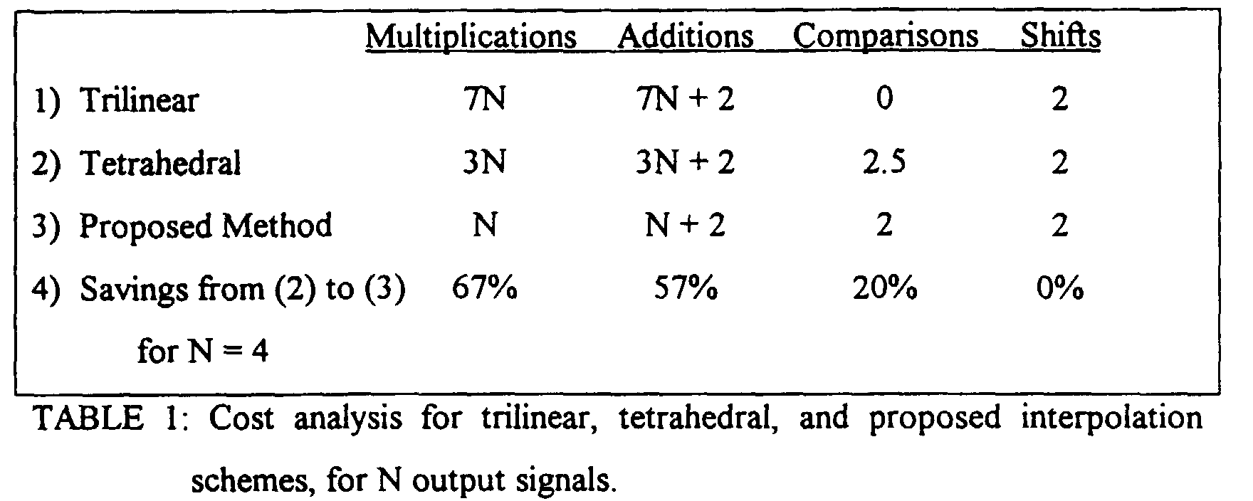
- Table 1 three methods, trilinear interpolation, tetrahedral interpolation, and the original embodiment of the present invention, are compared in terms of the computations required to perform the color correction operation at each pixel, for N output colors.
- This operation includes 1) retrieving the nodes of the sub-cell enclosing the input color; and 2) performing the actual interpolation.
- the comparison step in the multilevel halftoning operation has been included in the cost analysis.
- any quantities that do not depend on the input color are assumed to be precomputed and stored. These quantities include differences between output values at adjacent nodes, and the normalization of input values given by Equation (1).
- the last row of Table 1 shows the savings achieved by applying the present invention over tetrahedral interpolation. The savings would be even larger in comparison to trilinear interpolation.
Landscapes
- Engineering & Computer Science (AREA)
- Multimedia (AREA)
- Signal Processing (AREA)
- Facsimile Image Signal Circuits (AREA)
- Color Image Communication Systems (AREA)
- Image Processing (AREA)
Abstract
Description

Claims (2)
- A method of color transforming an input color value to an output color value in a digital imaging system which includes a multi-dimensional color transformation table, the color transformation table including an arrangement of nodes, each node defining an output color value, the method comprising the steps ofreceiving the input color value comprising a set of input color components;applying multilevel halftoning to a predetermined subset of the input color components to select a plurality of nodes constrained to a selected number of dimensions; andusing remaining others of the input color components to interpolate among the selected plurality of nodes to obtain the output color value.
- In an electronic imaging system which includes a receiver for receiving a set of input color components defining an input color, a conversion processor converting the input color to an output color, and image output apparatus for producing the output color on an output medium, the conversion processor comprising:a multi dimensional table having a plurality of nodes containing predefined output color data;a first quantizer receiving a predetermined subset of the input color components and identifying nodes constrained to a selected number of dimensions; andan interpolator for calculating an output color from the predefined color data contained at the nodes identified based on remaining ones of the input color components.
Applications Claiming Priority (2)
| Application Number | Priority Date | Filing Date | Title |
|---|---|---|---|
| US210006 | 1998-12-11 | ||
| US09/210,006 US6295137B1 (en) | 1998-12-11 | 1998-12-11 | Method of color correction using multi-level halftoning |
Publications (3)
| Publication Number | Publication Date |
|---|---|
| EP1011263A2 true EP1011263A2 (en) | 2000-06-21 |
| EP1011263A3 EP1011263A3 (en) | 2002-05-15 |
| EP1011263B1 EP1011263B1 (en) | 2006-05-03 |
Family
ID=22781243
Family Applications (1)
| Application Number | Title | Priority Date | Filing Date |
|---|---|---|---|
| EP99124398A Expired - Lifetime EP1011263B1 (en) | 1998-12-11 | 1999-12-07 | A method of color correction using multi-level halftoning |
Country Status (4)
| Country | Link |
|---|---|
| US (1) | US6295137B1 (en) |
| EP (1) | EP1011263B1 (en) |
| JP (1) | JP4429439B2 (en) |
| DE (1) | DE69931128T2 (en) |
Cited By (2)
| Publication number | Priority date | Publication date | Assignee | Title |
|---|---|---|---|---|
| EP1903775A1 (en) * | 2006-09-21 | 2008-03-26 | Thomson Licensing | Method for conversion of a colour space using separate chromatic and luminance look-up tables |
| WO2016119858A1 (en) * | 2015-01-29 | 2016-08-04 | Hewlett-Packard Development Company, L.P. | Color printing look-up-table |
Families Citing this family (7)
| Publication number | Priority date | Publication date | Assignee | Title |
|---|---|---|---|---|
| DE50107778D1 (en) * | 2001-03-01 | 2005-11-24 | Ball Packaging Europe Gmbh | LID COVER WITH DOUBLE LID MIRROR AND ITS MANUFACTURE |
| US6697582B1 (en) | 2003-01-15 | 2004-02-24 | Xerox Corporation | Dynamic control patches for better TRC control |
| US20060041609A1 (en) * | 2004-08-20 | 2006-02-23 | Pellar Ronald J | System and method for multi-dimensional lookup table interpolation |
| US20100027074A1 (en) * | 2008-07-31 | 2010-02-04 | Sharp Laboratories Of America, Inc. | Partition halftone for multi-tone level output device |
| US10127887B2 (en) * | 2015-01-14 | 2018-11-13 | Intel Corporation | Acceleration of color conversion |
| US9654667B1 (en) | 2016-05-06 | 2017-05-16 | Xerox Corporation | System and method for stochastic vector halftoning of contone data in a printer having variable printing parameters |
| US9641726B1 (en) | 2016-05-06 | 2017-05-02 | Xerox Corporation | Multi-ink vector halftoning using multi-bit vector halftoning methods |
Family Cites Families (10)
| Publication number | Priority date | Publication date | Assignee | Title |
|---|---|---|---|---|
| JP3371964B2 (en) * | 1992-09-08 | 2003-01-27 | アグファ ゲヴェルト ナームロゼ ベンノートチャップ | Method and apparatus for displaying characteristics of a color output device |
| US5377041A (en) | 1993-10-27 | 1994-12-27 | Eastman Kodak Company | Method and apparatus employing mean preserving spatial modulation for transforming a digital color image signal |
| JPH0877341A (en) | 1994-08-29 | 1996-03-22 | Xerox Corp | Equipment and method for color image processing |
| AU3590195A (en) * | 1994-09-16 | 1996-03-29 | Apple Computer, Inc. | A color correction system and method utilizing dithering |
| US5689350A (en) * | 1994-12-12 | 1997-11-18 | Xerox Corporation | Color printer calibration method for accurately rendering selected colors |
| US6421140B1 (en) * | 1995-12-08 | 2002-07-16 | Canon Kabushiki Kaisha | Color space conversion with simplified interpolation |
| US5650942A (en) * | 1996-02-02 | 1997-07-22 | Light Source Computer Images, Inc. | Appearance-based technique for rendering colors on an output device |
| JP3823424B2 (en) * | 1996-02-29 | 2006-09-20 | セイコーエプソン株式会社 | Image processing apparatus and image processing method |
| US5812744A (en) | 1996-04-30 | 1998-09-22 | Hewlett Packard Company | Joint design of dither matrices for a set of colorants |
| US5987169A (en) * | 1997-08-27 | 1999-11-16 | Sharp Laboratories Of America, Inc. | Method for improving chromatic text resolution in images with reduced chromatic bandwidth |
-
1998
- 1998-12-11 US US09/210,006 patent/US6295137B1/en not_active Expired - Lifetime
-
1999
- 1999-12-07 EP EP99124398A patent/EP1011263B1/en not_active Expired - Lifetime
- 1999-12-07 DE DE69931128T patent/DE69931128T2/en not_active Expired - Lifetime
- 1999-12-13 JP JP35274899A patent/JP4429439B2/en not_active Expired - Fee Related
Cited By (4)
| Publication number | Priority date | Publication date | Assignee | Title |
|---|---|---|---|---|
| EP1903775A1 (en) * | 2006-09-21 | 2008-03-26 | Thomson Licensing | Method for conversion of a colour space using separate chromatic and luminance look-up tables |
| US7847989B2 (en) | 2006-09-21 | 2010-12-07 | Thomson Licensing | Method for conversion of a colour space using separate chromatic and luminance look-up tables |
| WO2016119858A1 (en) * | 2015-01-29 | 2016-08-04 | Hewlett-Packard Development Company, L.P. | Color printing look-up-table |
| US10542185B2 (en) | 2015-01-29 | 2020-01-21 | Hewlett-Packard Development Company, L.P. | Color printing look-up-table |
Also Published As
| Publication number | Publication date |
|---|---|
| JP2000201279A (en) | 2000-07-18 |
| DE69931128D1 (en) | 2006-06-08 |
| EP1011263B1 (en) | 2006-05-03 |
| EP1011263A3 (en) | 2002-05-15 |
| JP4429439B2 (en) | 2010-03-10 |
| US6295137B1 (en) | 2001-09-25 |
| DE69931128T2 (en) | 2006-09-28 |
Similar Documents
| Publication | Publication Date | Title |
|---|---|---|
| US5553199A (en) | Method and apparatus for calibrating a four color printer | |
| US6421142B1 (en) | Out-of-gamut color mapping strategy | |
| JP3737149B2 (en) | Color image generation system and method | |
| US5809213A (en) | Automatic color calibration of a color reproduction system | |
| US5581376A (en) | System for correcting color images using tetrahedral interpolation over a hexagonal lattice | |
| EP0747853B1 (en) | Method and apparatus of refining a color imaging system of a printer | |
| EP0495914B2 (en) | Color digital halftoning with vector error diffusion | |
| US5854882A (en) | Halftone correction systems | |
| EP0487304B1 (en) | Color image processing | |
| US7382379B1 (en) | Arrangement for mapping colors between imaging systems and method thereof | |
| US6335800B1 (en) | Method of multidimensional interpolation for color transformations | |
| US5710827A (en) | Halftone dither cell with integrated preferred color matching | |
| US6882445B1 (en) | Color gamut compression apparatus and method | |
| US8593708B2 (en) | Methods, systems and apparatus for jointly optimizing node locations and corresponding output values of a color look-up-table (LUT) | |
| US6185004B1 (en) | Self-calibration for color image reproduction system | |
| US7355752B2 (en) | Two-dimensional calibration architectures for color devices | |
| US6707938B2 (en) | Principal axis look-up for color correction | |
| AU3916293A (en) | Color correction with a four-dimensional look-up table | |
| US7215440B2 (en) | Fast interpolation of large color lookup tables | |
| US6331899B1 (en) | Method and apparatus for automatically generating single-channel critical color transformations | |
| US6295137B1 (en) | Method of color correction using multi-level halftoning | |
| JPH11317882A (en) | Color image reproduction system, color conversion method, apparatus, and medium | |
| JPH05183742A (en) | Device for deciding color compensation parameter | |
| US5732151A (en) | Computerized memory mapping method for transforming color data | |
| US6574004B1 (en) | System and method for converting color data to gray data |
Legal Events
| Date | Code | Title | Description |
|---|---|---|---|
| PUAI | Public reference made under article 153(3) epc to a published international application that has entered the european phase |
Free format text: ORIGINAL CODE: 0009012 |
|
| AK | Designated contracting states |
Kind code of ref document: A2 Designated state(s): AT BE CH CY DE DK ES FI FR GB GR IE IT LI LU MC NL PT SE |
|
| AX | Request for extension of the european patent |
Free format text: AL;LT;LV;MK;RO;SI |
|
| PUAL | Search report despatched |
Free format text: ORIGINAL CODE: 0009013 |
|
| AK | Designated contracting states |
Kind code of ref document: A3 Designated state(s): AT BE CH CY DE DK ES FI FR GB GR IE IT LI LU MC NL PT SE |
|
| AX | Request for extension of the european patent |
Free format text: AL;LT;LV;MK;RO;SI |
|
| RIC1 | Information provided on ipc code assigned before grant |
Free format text: 7H 04N 1/56 A, 7H 04N 1/60 B |
|
| 17P | Request for examination filed |
Effective date: 20021115 |
|
| AKX | Designation fees paid |
Designated state(s): DE FR GB |
|
| 17Q | First examination report despatched |
Effective date: 20040218 |
|
| GRAP | Despatch of communication of intention to grant a patent |
Free format text: ORIGINAL CODE: EPIDOSNIGR1 |
|
| GRAS | Grant fee paid |
Free format text: ORIGINAL CODE: EPIDOSNIGR3 |
|
| GRAA | (expected) grant |
Free format text: ORIGINAL CODE: 0009210 |
|
| AK | Designated contracting states |
Kind code of ref document: B1 Designated state(s): DE FR GB |
|
| REG | Reference to a national code |
Ref country code: GB Ref legal event code: FG4D |
|
| REF | Corresponds to: |
Ref document number: 69931128 Country of ref document: DE Date of ref document: 20060608 Kind code of ref document: P |
|
| ET | Fr: translation filed | ||
| PLBE | No opposition filed within time limit |
Free format text: ORIGINAL CODE: 0009261 |
|
| STAA | Information on the status of an ep patent application or granted ep patent |
Free format text: STATUS: NO OPPOSITION FILED WITHIN TIME LIMIT |
|
| 26N | No opposition filed |
Effective date: 20070206 |
|
| PGFP | Annual fee paid to national office [announced via postgrant information from national office to epo] |
Ref country code: GB Payment date: 20131125 Year of fee payment: 15 Ref country code: DE Payment date: 20131121 Year of fee payment: 15 |
|
| PGFP | Annual fee paid to national office [announced via postgrant information from national office to epo] |
Ref country code: FR Payment date: 20131219 Year of fee payment: 15 |
|
| REG | Reference to a national code |
Ref country code: DE Ref legal event code: R119 Ref document number: 69931128 Country of ref document: DE |
|
| GBPC | Gb: european patent ceased through non-payment of renewal fee |
Effective date: 20141207 |
|
| REG | Reference to a national code |
Ref country code: FR Ref legal event code: ST Effective date: 20150831 |
|
| PG25 | Lapsed in a contracting state [announced via postgrant information from national office to epo] |
Ref country code: DE Free format text: LAPSE BECAUSE OF NON-PAYMENT OF DUE FEES Effective date: 20150701 Ref country code: GB Free format text: LAPSE BECAUSE OF NON-PAYMENT OF DUE FEES Effective date: 20141207 |
|
| PG25 | Lapsed in a contracting state [announced via postgrant information from national office to epo] |
Ref country code: FR Free format text: LAPSE BECAUSE OF NON-PAYMENT OF DUE FEES Effective date: 20141231 |