EP1011203A1 - Receiver and method of reception - Google Patents
Receiver and method of reception Download PDFInfo
- Publication number
- EP1011203A1 EP1011203A1 EP99922577A EP99922577A EP1011203A1 EP 1011203 A1 EP1011203 A1 EP 1011203A1 EP 99922577 A EP99922577 A EP 99922577A EP 99922577 A EP99922577 A EP 99922577A EP 1011203 A1 EP1011203 A1 EP 1011203A1
- Authority
- EP
- European Patent Office
- Prior art keywords
- signals
- digital
- circuit
- processing circuit
- digital broadcast
- Prior art date
- Legal status (The legal status is an assumption and is not a legal conclusion. Google has not performed a legal analysis and makes no representation as to the accuracy of the status listed.)
- Granted
Links
Images


Classifications
-
- H—ELECTRICITY
- H04—ELECTRIC COMMUNICATION TECHNIQUE
- H04H—BROADCAST COMMUNICATION
- H04H40/00—Arrangements specially adapted for receiving broadcast information
- H04H40/18—Arrangements characterised by circuits or components specially adapted for receiving
-
- H—ELECTRICITY
- H04—ELECTRIC COMMUNICATION TECHNIQUE
- H04B—TRANSMISSION
- H04B1/00—Details of transmission systems, not covered by a single one of groups H04B3/00 - H04B13/00; Details of transmission systems not characterised by the medium used for transmission
- H04B1/06—Receivers
- H04B1/16—Circuits
-
- H—ELECTRICITY
- H04—ELECTRIC COMMUNICATION TECHNIQUE
- H04B—TRANSMISSION
- H04B1/00—Details of transmission systems, not covered by a single one of groups H04B3/00 - H04B13/00; Details of transmission systems not characterised by the medium used for transmission
- H04B1/005—Details of transmission systems, not covered by a single one of groups H04B3/00 - H04B13/00; Details of transmission systems not characterised by the medium used for transmission adapting radio receivers, transmitters andtransceivers for operation on two or more bands, i.e. frequency ranges
-
- H—ELECTRICITY
- H04—ELECTRIC COMMUNICATION TECHNIQUE
- H04B—TRANSMISSION
- H04B1/00—Details of transmission systems, not covered by a single one of groups H04B3/00 - H04B13/00; Details of transmission systems not characterised by the medium used for transmission
- H04B1/06—Receivers
- H04B1/16—Circuits
- H04B1/1607—Supply circuits
- H04B1/1615—Switching on; Switching off, e.g. remotely
-
- H—ELECTRICITY
- H04—ELECTRIC COMMUNICATION TECHNIQUE
- H04B—TRANSMISSION
- H04B1/00—Details of transmission systems, not covered by a single one of groups H04B3/00 - H04B13/00; Details of transmission systems not characterised by the medium used for transmission
- H04B1/38—Transceivers, i.e. devices in which transmitter and receiver form a structural unit and in which at least one part is used for functions of transmitting and receiving
- H04B1/40—Circuits
- H04B1/403—Circuits using the same oscillator for generating both the transmitter frequency and the receiver local oscillator frequency
- H04B1/406—Circuits using the same oscillator for generating both the transmitter frequency and the receiver local oscillator frequency with more than one transmission mode, e.g. analog and digital modes
-
- H—ELECTRICITY
- H04—ELECTRIC COMMUNICATION TECHNIQUE
- H04H—BROADCAST COMMUNICATION
- H04H20/00—Arrangements for broadcast or for distribution combined with broadcast
- H04H20/28—Arrangements for simultaneous broadcast of plural pieces of information
- H04H20/33—Arrangements for simultaneous broadcast of plural pieces of information by plural channels
-
- H—ELECTRICITY
- H04—ELECTRIC COMMUNICATION TECHNIQUE
- H04L—TRANSMISSION OF DIGITAL INFORMATION, e.g. TELEGRAPHIC COMMUNICATION
- H04L27/00—Modulated-carrier systems
- H04L27/0008—Modulated-carrier systems arrangements for allowing a transmitter or receiver to use more than one type of modulation
-
- H—ELECTRICITY
- H04—ELECTRIC COMMUNICATION TECHNIQUE
- H04W—WIRELESS COMMUNICATION NETWORKS
- H04W52/00—Power management, e.g. TPC [Transmission Power Control], power saving or power classes
- H04W52/02—Power saving arrangements
- H04W52/0209—Power saving arrangements in terminal devices
- H04W52/0225—Power saving arrangements in terminal devices using monitoring of external events, e.g. the presence of a signal
- H04W52/0229—Power saving arrangements in terminal devices using monitoring of external events, e.g. the presence of a signal where the received signal is a wanted signal
-
- Y—GENERAL TAGGING OF NEW TECHNOLOGICAL DEVELOPMENTS; GENERAL TAGGING OF CROSS-SECTIONAL TECHNOLOGIES SPANNING OVER SEVERAL SECTIONS OF THE IPC; TECHNICAL SUBJECTS COVERED BY FORMER USPC CROSS-REFERENCE ART COLLECTIONS [XRACs] AND DIGESTS
- Y02—TECHNOLOGIES OR APPLICATIONS FOR MITIGATION OR ADAPTATION AGAINST CLIMATE CHANGE
- Y02D—CLIMATE CHANGE MITIGATION TECHNOLOGIES IN INFORMATION AND COMMUNICATION TECHNOLOGIES [ICT], I.E. INFORMATION AND COMMUNICATION TECHNOLOGIES AIMING AT THE REDUCTION OF THEIR OWN ENERGY USE
- Y02D30/00—Reducing energy consumption in communication networks
- Y02D30/70—Reducing energy consumption in communication networks in wireless communication networks
Definitions
- AM Amplitude Modulation
- FM Frequency modulation
- broadcast-wave signals are digital signals, it will become possible not only to broadcast high-quality audio data, but also to broadcast the audio data added with other data. It will also be possible to enhance the use efficiency of frequencies and accomplish broadcasting through more channels.
- a digital broadcasting receiver To receive digital signals, i.e., the broadcast waves of digital broadcasting, a digital broadcasting receiver must be used in place of an analog broadcasting receiver. In order to achieve smooth shift from the analog broadcasting to the digital broadcasting, it is desired that both the analog broadcasting and the digital broadcasting remain in service for a period of time.
- BOC In Band On Channel
- SA is the analog FM broadcast-wave signal (FM signal), and fRx is the carrier frequency of this signal.
- FM signal FM signal
- fRx the carrier frequency of this signal.
- two digital broadcast-wave signals SD are arranged on the sides of the broadcast-wave signal SA, close thereto, respectively. Only one broadcast-wave signal SD may be transmitted along with the analog broadcast-wave signal SA.
- the broadcast-wave signal SD represents the program that is identical to the program the broadcast-wave signal represents.
- the analog broadcast-wave signal SA will not be transmitted, and only the digital broadcast-wave signals SD will accomplish broadcasting.
- the frequency domain the broadcast-wave signal SA uses will be utilized for the digital broadcasting. It is estimated that 10 to 15 years will pass until the broadcasting shifts from the analog broadcasting to the digital broadcasting.
- receivers that can serve not only during the shift of broadcasting but also after the shift i.e., receivers that can receive analog broadcast signals and digital broadcast signals, must be provided, if the listeners want to enjoy both the analog broadcasting and the digital broadcasting.
- the power that an analog receiver consumes is about 30 mW, whereas the power a digital receiver consumes is 1 W, more or less. That is, the digital receiver consumes about 30 times as much power as the analog receiver.
- a receiver that can receive analog broadcast signals and digital broadcast signals will inevitably consume much power even while receiving analog broadcast signals.
- An object of the present invention is to provide a novel receiver and novel method, which can receive analog, broadcast signals and digital broadcast signals.
- Another object of the invention is to provide a receiver and method in which the power supply voltage applied to the digital processing circuit only when digital broadcast signals can be received, thereby to reduce power consumption.
- Still another object of the invention is to provide a receiver and method which can receive analog broadcast signals and digital broadcast signals and in which it can be accurately determined whether or not digital broadcasting is provided, thereby to reliably select a digital broadcast station.
- Another object of this invention is to provide a receiver and method for receiving analog broadcast signals and digital broadcast signals, which can reliably select an analog broadcast station.
- the present invention provides a receiver for use in a broadcasting system in which analog broadcast signals and digital broadcast signals are transmitted in adjacent frequency bands.
- the receiver has an analog processing circuit for receiving and processing analog broadcast-wave signals to extract audio signals; a digital signal processing circuit for receiving and processing digital broadcast-wave signals to extract audio signals; a changeover circuit for selecting either the audio signals supplied from the analog processing circuit or the audio signals supplied from the digital signal processing circuit; a control circuit for controlling the application of an operating power-supply voltage to the digital processing circuit; and a detecting circuit for detecting that a digital broadcast station has been selected.
- the control circuit applies the operating power-supply voltage to the digital processing circuit only when the detecting circuit detects that a digital broadcast station has been selected.
- This invention also provides a receiver for use in a broadcasting system in which analog broadcast signals and digital broadcast signals are transmitted in adjacent frequency bands.
- the receiver has a circuit for selecting a station in accordance with an analog broadcast-wave signal, an analog processing circuit for receiving and processing analog broadcast-wave signals to extract audio signals; a digital signal processing circuit for receiving and processing digital broadcast-wave signals to extract audio signals; a changeover circuit for selecting either the audio signals supplied from the analog processing circuit or the audio signals supplied from the digital signal processing circuit; a control circuit for controlling the application of an operating power-supply voltage to the digital processing circuit; and a detecting circuit for detecting that a digital broadcast station has been selected.
- the control circuit applies the operating power-supply voltage to the digital processing circuit only when the detecting circuit detects that a digital broadcast station has been selected. When the detecting circuit does not detect that a digital broadcast station has been selected, the control circuit stops applying the operating power-supply voltage to the digital processing circuit.
- the present invention provides a receiver for use in a broadcasting system in which analog broadcast signals and digital broadcast signals are transmitted in adjacent frequency bands.
- the receiver has a circuit for selecting a station in accordance with an analog broadcast-wave signal, an analog processing circuit for receiving and processing analog broadcast-wave signals to extract audio signals; a digital signal processing circuit for receiving and processing digital broadcast-wave signals to extract audio signals; a changeover circuit for selecting either the audio signals supplied from the analog processing circuit or the audio signals supplied from the digital signal processing circuit; a control circuit for controlling the application of an operating power-supply voltage to the digital processing circuit; and a detecting circuit for detecting that a digital broadcast station has been selected.
- the control circuit applies the operating power-supply voltage to the digital processing circuit only when the circuit for selecting a station cannot receive analog broadcast waves at the time of selecting a station and when the detecting circuit detects that a digital broadcast station has been selected. When the detecting circuit does not detect that digital broadcast signals are received, the control circuit stops applying the operating power-supply voltage to the digital processing circuit.
- the invention provides a receiver for use in a broadcasting system in which analog broadcast signals and digital broadcast signals are transmitted in adjacent frequency bands.
- the receiver has a circuit for selecting a station in accordance with a digital broadcast-wave signal, an analog processing circuit for receiving and processing analog broadcast-wave signals to extract audio signals; a digital signal processing circuit for receiving and processing digital broadcast-wave signals to extract audio signals; a changeover circuit for selecting either the audio signals supplied from the analog processing circuit or the audio signals supplied from the digital signal processing circuit; a control circuit for controlling the application of an operating power-supply voltage to the digital processing circuit; and a detecting circuit for detecting that a digital broadcast station has been selected.
- the control circuit applies the operating power-supply voltage to the digital processing circuit only when the circuit for selecting a station receives digital broadcast waves and detects that a digital broadcast station has been selected, at the time of selecting a station.
- the control circuit stops applying the operating power-supply voltage to the digital processing circuit.
- this invention provides a receiving method for use in a broadcasting system in which analog broadcast signals and digital broadcast signals are transmitted in adjacent frequency bands.
- analog broadcast-wave signals are received at the time of selecting a station, to determine whether or not a digital broadcast station has been selected. Only when it is determined that a digital broadcast station has been selected, an operating power-supply voltage is applied to a digital processing circuit that processes the digital broadcast-wave signals which have been received and extracts audio signals. When it is not determined that a digital broadcast station has been selected, the application of the operating power-supply voltage to the digital processing circuit is stopped.
- the present invention provides a receiving method for use in a broadcasting system in which analog broadcast signals and digital broadcast signals are transmitted in adjacent frequency bands.
- digital broadcast-wave signals are received at the time of selecting a station. Only when it is determined that a digital broadcast station has been selected, an operating power-supply voltage is applied to a digital processing circuit that processes the digital broadcast-wave signals which have been received and extracts audio signals. When it is not determined that a digital broadcast station has been selected, the application of the operating power-supply voltage to the digital processing circuit is stopped.
- the receiver according to the invention is designed for use in a broadcasting system in which analog broadcast signals and digital broadcast signals are transmitted in adjacent frequency bands.
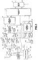
- the receiver comprises a microcomputer 40 for controlling the system.
- Various operation keys (switches) 41 are connected to the microcomputer 40.
- the receiver receives waves in the following manner while it keeps receiving analog broadcast waves or digital broadcast waves.
- the broadcast wave that an antenna 11 has received is supplied to an antenna tuning circuit 12 of electronic tuning type, thereby extracting a received signal SRX of the target frequency fRX.
- the signal SRX is supplied via a high-frequency amplifier 13 to the first mixer circuit 14I and second mixer circuit 14Q.
- a local oscillation circuit 15, which comprises a PLL, selects a station as the operation keys 41 are operated. Then, the microcomputer 40 controls the oscillation frequency of the local oscillation circuit 15.
- Local oscillation signals SLI and SLQ which have the frequency equal to the reception frequency fRX and differ from each other in phase by 90°, are thereby generated. These signals SLI and SLQ are supplied to mixer circuits 14I and 14Q, respectively.
- a control voltage is applied to the VCO (not shown) of the PLL constituting the local oscillation circuit 15.
- a pan of this control voltage is applied, as station-selecting voltage, to the antenna tuning circuit 12.
- the signal SRX received is converted in frequency in the mixer circuits 14I and 14Q, to intermediate-frequency signals SLI and SLQ.
- the signals SLI and SLQ are output from the mixer circuits 141 and 14Q.
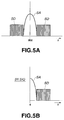
- the frequency fRX of the local oscillation signals SLI and SLQ is equal to the reception frequency fRX. Therefore, the intermediate-frequency signals SII and SIQ have an intermediate frequency of 0 as is illustrated in, for example, FIG. 5B while the receiver is receiving such broadcast waves as is shown in FIG. 5A.
- signals SAI and SAQ frequency-converted from an analog broadcast-wave signal SA are present on the low-frequency side, whereas signals SDI and SDQ frequency-converted from a digital broadcast-wave signal SD are present on the high-frequency side.
- the signals SAI and SAQ frequency-converted from an analog broadcast-wave signal SA have phases which are equal to those of the local oscillation signals SLI and SLQ, respectively, and which therefore differ from each other by 90°.
- the intermediate-frequency signals SII and SIQ are supplied to low-pass filters 21I and 21Q, which extract signals SAI and SAQ.
- the signals SAI and SAQ have been frequency-converted from the analog broadcast-wave signal SA, from the intermediate-frequency signals SII and SIQ, respectively.
- These signals SAI and SAQ are supplied to an analog processing circuit 24 first through switch circuits 22I and 22Q, which will be described later, and then through amplifiers 23I and 23Q.
- the processing circuit 24 performs phase processing and operations on the signals SAI and SAQ and also stereophonic demodulation on them, thus extracting from the signals SAI and SAQ audio signals L and R for analog broadcasting.
- the audio signals L and R are supplied to a changeover circuit 16.
- the intermediate-frequency signals SII and SIQ output from the mixer circuits 14I and 14Q are supplied to band-pass filters 31I and 31Q.
- the filters 31I and 31Q extract signals SDI and SDQ, which have been frequency-converted from the digital broadcast-wave signal SD, from the intermediate-frequency signals SII and SIQ.
- the signals SDI and SDQ are supplied to the switch circuits 22I and 22Q. They are also supplied to a digital processing circuit 34 via amplifiers 33I and 33Q.
- This processing circuit 34 is compatible with the digital broadcasting and demodulates the audio signals L and R from the intermediate-frequency signals SDI and SDQ.
- the audio signals L and R are supplied to the changeover circuit 16.
- the amplifiers 33I and 33Q and processing circuit 34 are integrated in, for example, a one-chip IC 30.
- the microcomputer 40 supplies a control signal S40 to the changeover circuit 16.
- the changeover circuit 16 selects either the audio signals L and R supplied from the processing circuit 24 or the audio signals supplied from the processing circuit 34.
- the audio signals L and R selected are output via a muting circuit 17, as a received analog output or a received digital output.
- the muting circuit 17 receives a muting control signal S17 from the microcomputer 40.
- the receiver according to the present invention further comprises the following components.
- the intermediate-frequency signals SAI and SAQ output from the low-pass filters 21I and 21Q are supplied to the amplifiers 23I and 23Q through the switch circuits 22I and 22Q, provided that the switch circuits 22I and 22Q are connected in the sate illustrated in FIG. 1. If the switch circuits 22I and 22Q are connected in the state reverse to the state shown in FIG. 1, the intermediate-frequency signals SDI and SDQ output from the band-pass filters 31I and 31Q are supplied to the amplifiers 23I and 23Q through the switch circuits 22I and 22Q.
- the intermediate-frequency signals (signals SAI and SAQ or signals SDI and SDQ) are supplied from the amplifiers 23I and 23Q to a level-detecting circuit 51.
- the circuit 51 detects whether the broadcast-wave signal (analog broadcast-wave signal SA or digital broadcast-wave signal SD) can be received at a level higher than a predetermined level, and generates a detection signal S51.
- the detection signal S51 is supplied to the microcomputer 40.
- the level-detecting circuit 51 is generally known also as RSSI (Received Signal Strength Indicator) circuit.
- a signal (synchronizing flag) S34 is fetched from the processing circuit 34, The signal S34 indicates whether the digital processing in the processing circuit 34 is synchronized or not.
- the signal S34 is supplied to the microcomputer 40.
- a switch circuit 52 is connected to the power-supply line extending from the amplifier 33I to the processing circuit 34, i.e., the power-supply line of the IC 30.
- the switch circuit 52 is used as a circuit for controlling the supply of power through the power-supply line.
- the microcomputer 40 supplies a control signal 52 to the switch circuit 52.
- the microcomputer 40 also supplies a control signal S40 to the switch circuits 22I and 22Q.
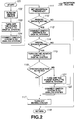
- the microcomputer 40 is provided with, for example, the reception routine 100 illustrated in FIG. 2.
- the routine 100 is a part of the program that the CPU (not shown) incorporated in the microcomputer 40 executes.
- a station may be selected. If so, the CPU in the microcomputer 40 starts operating in Step 101 of the routine 100, as is illustrated in FIG. 2.
- the muting control signal S17 controls the muting circuit 17, whereby muting is effected.
- the control signal S52 turns off the switch circuit 52, turning off the power supply of the IC 30.
- Step S104 the switch circuits 22I and 22Q are connected to the low-pass filters 21I and 21Q as shown in FIG. 1, by virtue of the control signal S40.
- the changeover circuit 16 is connected to the analog processing circuit 24, also virtue of the control signal S40. From this time on, the receipt level of an analog broadcast signal can be detected in the detecting circuit 51.
- Step 111 data representing a predetermined frequency is supplied to the local oscillation circuit 15, setting the reception frequency at the target value fRX.
- Step 112 the detection signal S51 from the detecting circuit 51 is checked, thus determining whether or not it is possible to receive broadcast signals. More precisely, it is determined whether analog broadcast signals can be received since this step is carried out after Step 104 has been performed.
- Step 113 the switch circuits 22I and 22Q are connected to the band-pass filters 31I and 31Q in the state reverse to the state shown in FIG. 1 by virtue of the control signal S40.
- the changeover circuit 16 is connected to the processing circuit 34 by virtue of the control signal S40, too. From this time on, the receipt level of a digital broadcast signal can be detected in the detecting circuit 51.
- Step 114 the detection signal S51 from the detection circuit 51 is checked. It is thereby determined whether or not it is possible to receive broadcast signals. More specifically, it is determined whether digital broadcast signals can be received, because Step 114 is performed after Step 113 has been carried out. If it is determined that digital broadcast signals can be received, the processing goes from Step 114 to Step 115.
- Step 115 the control signal S52 turns on the switch circuit 52, whereby the power-supply voltage is applied to the IC 30. Hence, the IC 30 starts demodulating the audio signals L and R supplied from the intermediate-frequency signals SDI and SDQ for digital broadcasting.
- Step 116 the signal S34 is checked. Thus, in the digital processing circuit 116 it is determined whether the digital processing in the processing circuit 34 is synchronized or not. If the digital processing is synchronized, the processing goes from Step 116 to Step 117. In Step 117, the muting circuit 17 is turned off, terminating the muting. From this time on, the audio signals L and R extracted from the digital broadcast signal are output via the muting circuit 17, because the changeover circuit 16 has been connected to the digital processing circuit 34 in Step 113. In Step 118 that follows Step 117, the processing of the routine 100 ends.
- the digital broadcasting is selected and the audio signals L and R transmitted by digital broadcasting are output, as long as the receiver is able to receive the digital broadcast signals.
- Step 116 If the digital processing is not synchronized in Step 116, the processing goes from Step 116 to Step 121.
- Step 121 the control signal S52 turns off the switch circuit 52, whereby the IC 30 is turned off.
- Step 122 the switch circuits 22I and 22Q are connected to the low-pass filters 21I and 21Q as shown in FIG. 1, and the changeover circuit 16 is connected to the analog processing circuit 24, by virtue of the control signal S40. Thereafter, the processing goes from Step 116 to Step 117.
- Step 117 the muting in the muting circuit 17 is turned off. From this time on, the audio signals L and R transmitted by analog broadcasting are output. That is, the audio signals L and R transmitted by analog broadcasting are output in the case where the digital processing is not synchronized even though the receiver has received the digital broadcast signals.
- Step 114 If it is determined in Step 114 that digital broadcast signals cannot be received, the processing goes from Step 114 to Step 122.
- the analog broadcasting is selected, whereby the audio signals L and R transmitted by the analog broadcasting are output.
- Step 112 If it is determined in Step 112 that analog broadcast signals cannot be received, the processing goes from Step 112 to Step 118. In this case, no broadcast waves are selected.
- the reception routine 100 is executed again at the next reception frequency. At this time, the IC 30, which has been turned off in Step 103, remains off.
- the receiver according to the present invention can executed such reception routine 200 as shown in FIG. 3.
- Steps 201 to 211 and Steps 213 to 217 are identical to Steps 101 to 111 and Steps 113 to 117 of the reception routine 100 that is illustrated in FIG. 2. Therefore, Steps 201 to 211 and Steps 213 to 217 will not be described.
- Step 212 it may be determined that analog broadcast signals cannot be received. If so, the processing advances to Step 231.
- the switch circuits 22I and 22Q are connected to the band-pass filters 31I and 31Q in the state reverse to the state of FIG. 1, and the changeover circuit 16 is connected to the digital processing circuit 34, by virtue of the control signal S40. This enables the detecting circuit 51 to detect the receipt level of a digital broadcast signal.
- Step 232 the detection signal S51 from the detecting circuit 51 is checked. It is thereby determined whether broadcast signals can be received or not. Since Step 232 is effected after Step 231, it is determined whether digital broadcast signals can be received or not. If digital broadcast signals can be received, the processing goes from Step 232 to Step 233. In Step 233, the control signal S52 turns on the switch circuit 52. The power-supply voltage is thereby applied to the IC 30. Hence, the IC 30 performs the processing for demodulating the audio signals L and R extracted from the intermediate-frequency signals SDI and SDQ for digital broadcasting.
- Step 234 the signal S34 is checked, thereby determining whether the processing in the processing circuit 34 has been synchronized or not. If the process has been synchronized, the processing goes from Step 234 to Step 217.
- Step 217 the muting circuit 17 stops the muting. From this time on, the audio signals L and R transmitted by digital broadcasting are output through the muting circuit 17. This is because the changeover circuit 16 has been connected to the digital processing circuit 34 in Step 231.
- the reception routine 200 ends in the following Step 218.
- the digital broadcasting is selected, and the audio signals L and R transmitted by digital broadcasting are output in the case where the receiver can receive digital broadcast signals although it cannot receive analog broadcast signals.
- Step 241 the control signal S52 turns off the switch circuit 52, thus turning off the IC 30. The processing is thereby terminated in Step 218.
- Step 232 the processing goes from Step 232 to Step 218. In this case, the selection of broadcasting is not effected.
- the reception routine 200 is executed again at the next reception frequency. At this time, the IC 30, which has been turned off in Step 203, remains off.
- the receiver and receiving method it is first determined whether or not analog broadcast signals can be received. Then, it is determined whether digital broadcast signals of a frequency band adjacent to the frequency band of the analog broadcast signals can be received or not. Only if the digital broadcast signals can be received, the operating voltage is applied to the digital processing circuit 34. The cost of power consumption can be therefore reduced.
- the digital processing circuit 34 At the time of selecting a station, the digital processing circuit 34 has already stopped operating. Hence, the noise signals generated in the digital processing circuit 34 would not inhibit the selection of a station or the detection of receipt level. In addition, it is possible to determine accurately whether or not digital broadcasting is provided.
- the reception routine 100 or 200 is executed at the time of selecting a station. Nonetheless, the routine can be executed when the power-supply switch is turned on. If this is the case, the last channel, i.e., the frequency at which signals were received when the power-supply switch was turned off, may be set in Step 111 or 211.
- reception routine 100 or 200 it is first determined whether analog broadcast signals can be received or not and it is then determined whether digital broadcast signals can be received or not. Instead, it can be first determined, of course, whether digital broadcast signals can be received or not. A reception routine that enables this will be described, with reference to FIG. 4.
- Steps 301 to 303 are identical to Steps 101 to 103of the reception routine 100 that is shown in FIG. 2. Therefore, Steps 301 to 303 will not be explained.
- the switch circuits 22I and 22Q are connected to the band-pass filters 31I and 31Q in the state reverse to the state shown in FIG. 1, by virtue of the control signal S40. Further, the changeover circuit 16 is connected to the digital processing circuit 34 by virtue of the control signal S40. From this time on, the detecting circuit 51 can detect the receipt level of a digital broadcast signal.
- Step 311 data representing a predetermined frequency is supplied to the local oscillation circuit 15.
- the reception frequency is thereby set at the target value fRX.
- Step 312 the detection signal S51 output from the detecting circuit 51 is checked. It is thereby determined whether broadcast signals can be received or not. More precisely, it is determined, in this case, whether digital broadcast signals can be received, because this step is carried out after Step 304 has been performed.
- Step 321 the control signal S52 turns on the switch circuit 52, whereby the power-supply voltage is applied to the IC 30. Thereafter, the IC 30 performs the processing for demodulating the audio signals L and R extracted from the intermediate-frequency signals SDI and SDQ for digital broadcasting.
- Step 322 the signal S34 is checked. It is thereby determined whether the processing has been synchronized or not in the digital processing circuit 34. If the processing has been synchronized, the processing goes from Step 322 to Step 315. In Step 315, the muting circuit 17 is turned off, stopping the muting. At this time, the changeover circuit 16 has been connected to the digital processing circuit 34 in Step 304. From this time on, the audio signals L and R transmitted by digital broadcasting are output through the muting circuit 17. The execution of the reception routine 300 is terminated in the next Step 316.
- Step 322 If it is determined in Step 322 that the processing has not been synchronized, the processing goes from Step 322 to Step 331.
- Step 331 the control signal S52 turns off the switch circuit 52. The supply of the power to the IC 30 is thereby stopped. The processing ends in Step 316.
- Step 312 If it is determined in Step 312 that digital broadcast signals cannot be received, the processing advances to Step 313.
- the switch circuits 22I and 22Q are connected to the low-pass filters 21I and 21Q by virtue of the control signal S40, in such a state as is illustrated in the figure.
- the changeover circuit 16 is connected to the analog processing circuit 24 by virtue of the control signal S40, too. This enables the detecting circuit 51 to detect the receipt level of an analog broadcast signal.
- Step 314 the detection signal S51 generated by the detecting circuit 51 is checked, determining whether broadcast signals can be received or not. In this case, it is determined whether or not analog broadcast signals can be received since this step is carried out after Step 313 has been performed.
- Step 315 the muting circuit 17 is turned off, thus stopping the muting.
- the changeover circuit 16 which was connected to the analog processing circuit 24 in Step 313, remains connected to the analog processing circuit 24. From this tune on, the audio signals L and R transmitted by analog broadcasting are therefore output via the muting circuit 17.
- Step 316 the reception routine 300 is completed.
- the analog broadcasting is selected and the audio signals L and R transmitted by the analog broadcasting are output, if analog broadcast signals can be received, though digital broadcast signals cannot be received.
- Step 314 If it is determined in Step 314 that analog broadcast signals cannot be received, the processing goes from Step 314 to Step 316.
- Step 316 the reception routine 300 is completed. In this case, the selection of broadcasting is not carried out. Hence, to select a station by means of, for example, scanning, the reception routine 300 is executed again at the next reception frequency.
- Analog broadcast signals may be received in Step 112 of the reception routine 100 shown in FIG. 2 or in Step 212 of the reception routine 200 shown in FIG. 3.
- the audio signals L and R transmitted by analog broadcasting may be output from the muting circuit 17. If digital broadcast signals are received thereafter, the audio signals L and R transmitted by digital broadcasting may be output instead. Whether or not digital broadcast signals can be received may be determined at prescribed intervals.
- the broadcasting may be switched, from analog broadcasting to digital broadcasting or vice versa. That is, the listener can select whichever broadcasting he or she likes, either analog broadcasting or digital broadcasting, as long as both types of broadcasting are provided.
- the switch circuit 52 may be any circuit that minimizes the power consumption in the digital processing circuit 34 while the receiver is receiving no digital broadcast signals.
- Step 116 shown in FIG. 2, Steps 216 and 234 shown in FIG. 3, and Step 322 shown in FIG. 4 may not be performed. This is because they are steps for enhancing the reliability of determining whether the processing has not been synchronized.
- the supply of power to the digital processing circuit is stopped when digital broadcast signals cannot be received, thereby terminating the reception routines 100, 200 and 300 shown in FIG. 2, FIG. 3 and FIG. 4, respectively.
- a step of detecting whether digital broadcast signals can be received may be repeated at prescribed intervals.
- the operating power-supply voltage may be applied to the digital processing circuit if the digital broadcast signals received are detected.
- the audio signals L and R transmitted by digital broadcasting may then be output through the muting circuit 17.
- an analog processing circuit for receiving and processing analog broadcast-wave signals to extract audio signals; a digital signal processing circuit for receiving and processing digital broadcast-wave signals to extract audio signals; a changeover circuit for selecting either the audio signals supplied from the analog processing circuit or the audio signals supplied from the digital signal processing circuit; a control circuit for controlling the application of an operating power-supply voltage to the digital processing circuit; and a detecting circuit for detecting that a digital broadcast station has been selected.
- the control circuit applies the operating power-supply voltage to the digital processing circuit only when the detecting circuit detects that a digital broadcast station has been selected.
Abstract
Description
- The present invention relates to a receiver for receiving broadcast waves and a method of receiving broadcast waves, and more particularly to a receiver and a method for receiving waves, both for use in a broadcasting system in which analog broadcast waves and digital broadcast waves are transmitted in adjacent frequency bands.
- In the AM (Amplitude Modulation) broadcasting and the FM (Frequency modulation) broadcasting, an analog system is employed wherein the broadcast- wave signals are analog signals though the source audio data to be broadcast is convened to digital data.
- If the broadcast-wave signals are digital signals, it will become possible not only to broadcast high-quality audio data, but also to broadcast the audio data added with other data. It will also be possible to enhance the use efficiency of frequencies and accomplish broadcasting through more channels.
- To receive digital signals, i.e., the broadcast waves of digital broadcasting, a digital broadcasting receiver must be used in place of an analog broadcasting receiver. In order to achieve smooth shift from the analog broadcasting to the digital broadcasting, it is desired that both the analog broadcasting and the digital broadcasting remain in service for a period of time.
- A broadcasting system called BOC (In Band On Channel) system has been proposed as a broadcasting system that performs both analog broadcasting and digital broadcasting. The IBOC system effects both types of broadcasting by allocating frequencies to the analog broadcasting and digital broadcasting as is illustrated in FIG. 5A.
- In FIG. 5A, SA is the analog FM broadcast-wave signal (FM signal), and fRx is the carrier frequency of this signal. To transmit digital broadcast-wave signals SD together with the analog broadcast-wave signal SA, two digital broadcast-wave signals SD are arranged on the sides of the broadcast-wave signal SA, close thereto, respectively. Only one broadcast-wave signal SD may be transmitted along with the analog broadcast-wave signal SA. Generally, the broadcast-wave signal SD represents the program that is identical to the program the broadcast-wave signal represents. In the future, the analog broadcast-wave signal SA will not be transmitted, and only the digital broadcast-wave signals SD will accomplish broadcasting. Alternatively, the frequency domain the broadcast-wave signal SA uses will be utilized for the digital broadcasting. It is estimated that 10 to 15 years will pass until the broadcasting shifts from the analog broadcasting to the digital broadcasting.
- Hence, receivers that can serve not only during the shift of broadcasting but also after the shift, i.e., receivers that can receive analog broadcast signals and digital broadcast signals, must be provided, if the listeners want to enjoy both the analog broadcasting and the digital broadcasting.
- The power that an analog receiver consumes is about 30 mW, whereas the power a digital receiver consumes is 1 W, more or less. That is, the digital receiver consumes about 30 times as much power as the analog receiver. Thus, a receiver that can receive analog broadcast signals and digital broadcast signals will inevitably consume much power even while receiving analog broadcast signals.
- An object of the present invention is to provide a novel receiver and novel method, which can receive analog, broadcast signals and digital broadcast signals.
- Another object of the invention is to provide a receiver and method in which the power supply voltage applied to the digital processing circuit only when digital broadcast signals can be received, thereby to reduce power consumption.
- Still another object of the invention is to provide a receiver and method which can receive analog broadcast signals and digital broadcast signals and in which it can be accurately determined whether or not digital broadcasting is provided, thereby to reliably select a digital broadcast station.
- Another object of this invention is to provide a receiver and method for receiving analog broadcast signals and digital broadcast signals, which can reliably select an analog broadcast station.
- To attain these objects, the present invention provides a receiver for use in a broadcasting system in which analog broadcast signals and digital broadcast signals are transmitted in adjacent frequency bands. The receiver has an analog processing circuit for receiving and processing analog broadcast-wave signals to extract audio signals; a digital signal processing circuit for receiving and processing digital broadcast-wave signals to extract audio signals; a changeover circuit for selecting either the audio signals supplied from the analog processing circuit or the audio signals supplied from the digital signal processing circuit; a control circuit for controlling the application of an operating power-supply voltage to the digital processing circuit; and a detecting circuit for detecting that a digital broadcast station has been selected. The control circuit applies the operating power-supply voltage to the digital processing circuit only when the detecting circuit detects that a digital broadcast station has been selected.
- This invention also provides a receiver for use in a broadcasting system in which analog broadcast signals and digital broadcast signals are transmitted in adjacent frequency bands. The receiver has a circuit for selecting a station in accordance with an analog broadcast-wave signal, an analog processing circuit for receiving and processing analog broadcast-wave signals to extract audio signals; a digital signal processing circuit for receiving and processing digital broadcast-wave signals to extract audio signals; a changeover circuit for selecting either the audio signals supplied from the analog processing circuit or the audio signals supplied from the digital signal processing circuit; a control circuit for controlling the application of an operating power-supply voltage to the digital processing circuit; and a detecting circuit for detecting that a digital broadcast station has been selected. The control circuit applies the operating power-supply voltage to the digital processing circuit only when the detecting circuit detects that a digital broadcast station has been selected. When the detecting circuit does not detect that a digital broadcast station has been selected, the control circuit stops applying the operating power-supply voltage to the digital processing circuit.
- Further, the present invention provides a receiver for use in a broadcasting system in which analog broadcast signals and digital broadcast signals are transmitted in adjacent frequency bands. The receiver has a circuit for selecting a station in accordance with an analog broadcast-wave signal, an analog processing circuit for receiving and processing analog broadcast-wave signals to extract audio signals; a digital signal processing circuit for receiving and processing digital broadcast-wave signals to extract audio signals; a changeover circuit for selecting either the audio signals supplied from the analog processing circuit or the audio signals supplied from the digital signal processing circuit; a control circuit for controlling the application of an operating power-supply voltage to the digital processing circuit; and a detecting circuit for detecting that a digital broadcast station has been selected. The control circuit applies the operating power-supply voltage to the digital processing circuit only when the circuit for selecting a station cannot receive analog broadcast waves at the time of selecting a station and when the detecting circuit detects that a digital broadcast station has been selected. When the detecting circuit does not detect that digital broadcast signals are received, the control circuit stops applying the operating power-supply voltage to the digital processing circuit.
- Moreover, the invention provides a receiver for use in a broadcasting system in which analog broadcast signals and digital broadcast signals are transmitted in adjacent frequency bands. The receiver has a circuit for selecting a station in accordance with a digital broadcast-wave signal, an analog processing circuit for receiving and processing analog broadcast-wave signals to extract audio signals; a digital signal processing circuit for receiving and processing digital broadcast-wave signals to extract audio signals; a changeover circuit for selecting either the audio signals supplied from the analog processing circuit or the audio signals supplied from the digital signal processing circuit; a control circuit for controlling the application of an operating power-supply voltage to the digital processing circuit; and a detecting circuit for detecting that a digital broadcast station has been selected. The control circuit applies the operating power-supply voltage to the digital processing circuit only when the circuit for selecting a station receives digital broadcast waves and detects that a digital broadcast station has been selected, at the time of selecting a station. When the detecting circuit receiving digital broadcast waves does not detect that digital broadcast signals are received, the control circuit stops applying the operating power-supply voltage to the digital processing circuit.
- Still further, this invention provides a receiving method for use in a broadcasting system in which analog broadcast signals and digital broadcast signals are transmitted in adjacent frequency bands. In the method, analog broadcast-wave signals are received at the time of selecting a station, to determine whether or not a digital broadcast station has been selected. Only when it is determined that a digital broadcast station has been selected, an operating power-supply voltage is applied to a digital processing circuit that processes the digital broadcast-wave signals which have been received and extracts audio signals. When it is not determined that a digital broadcast station has been selected, the application of the operating power-supply voltage to the digital processing circuit is stopped.
- Furthermore, the present invention provides a receiving method for use in a broadcasting system in which analog broadcast signals and digital broadcast signals are transmitted in adjacent frequency bands. In this method, digital broadcast-wave signals are received at the time of selecting a station. Only when it is determined that a digital broadcast station has been selected, an operating power-supply voltage is applied to a digital processing circuit that processes the digital broadcast-wave signals which have been received and extracts audio signals. When it is not determined that a digital broadcast station has been selected, the application of the operating power-supply voltage to the digital processing circuit is stopped.
- The other objects of the invention and the specific advantages resulting from the invention will be more clearly understood from the following description of the embodiments.
-
- FIG. 1 is a block diagram showing a receiver according to the present invention;
- FIG. 2 is a flow chart for explaining the first example of the procedure in which the receiver of the invention receives broadcast waves;
- FIG. 3 is a flow chart for explaining the second example of the procedure in which the receiver of the invention receives broadcast waves;
- FIG. 4 is a flow chart for explaining the third example of the procedure in which the receiver of the invention receive broadcast waves; and
- FIG. 5A and 5B are diagrams illustrating the frequency scheme applied to the case where a digital broadcast wave and an analog broadcast wave are transmitted together.
-
- An embodiment of this invention, which is applied to a receiver of direct-conversion type, will be described below.
- The receiver according to the invention is designed for use in a broadcasting system in which analog broadcast signals and digital broadcast signals are transmitted in adjacent frequency bands. As shown in FIG. 1, the receiver comprises a
microcomputer 40 for controlling the system. Various operation keys (switches) 41 are connected to themicrocomputer 40. - The receiver receives waves in the following manner while it keeps receiving analog broadcast waves or digital broadcast waves.
- The broadcast wave that an
antenna 11 has received is supplied to anantenna tuning circuit 12 of electronic tuning type, thereby extracting a received signal SRX of the target frequency fRX. The signal SRX is supplied via a high-frequency amplifier 13 to the first mixer circuit 14I andsecond mixer circuit 14Q. Alocal oscillation circuit 15, which comprises a PLL, selects a station as theoperation keys 41 are operated. Then, themicrocomputer 40 controls the oscillation frequency of thelocal oscillation circuit 15. Local oscillation signals SLI and SLQ, which have the frequency equal to the reception frequency fRX and differ from each other in phase by 90°, are thereby generated. These signals SLI and SLQ are supplied tomixer circuits 14I and 14Q, respectively. A control voltage is applied to the VCO (not shown) of the PLL constituting thelocal oscillation circuit 15. A pan of this control voltage is applied, as station-selecting voltage, to theantenna tuning circuit 12. The signal SRX received is converted in frequency in themixer circuits 14I and 14Q, to intermediate-frequency signals SLI and SLQ. The signals SLI and SLQ are output from themixer circuits - In this case, the frequency fRX of the local oscillation signals SLI and SLQ is equal to the reception frequency fRX. Therefore, the intermediate-frequency signals SII and SIQ have an intermediate frequency of 0 as is illustrated in, for example, FIG. 5B while the receiver is receiving such broadcast waves as is shown in FIG. 5A. Thus, signals SAI and SAQ frequency-converted from an analog broadcast-wave signal SA are present on the low-frequency side, whereas signals SDI and SDQ frequency-converted from a digital broadcast-wave signal SD are present on the high-frequency side. In this instance, the signals SAI and SAQ frequency-converted from an analog broadcast-wave signal SA have phases which are equal to those of the local oscillation signals SLI and SLQ, respectively, and which therefore differ from each other by 90°.
- The intermediate-frequency signals SII and SIQ are supplied to low-
pass filters 21I and 21Q, which extract signals SAI and SAQ. The signals SAI and SAQ have been frequency-converted from the analog broadcast-wave signal SA, from the intermediate-frequency signals SII and SIQ, respectively. These signals SAI and SAQ are supplied to ananalog processing circuit 24 first throughswitch circuits 22I and 22Q, which will be described later, and then throughamplifiers 23I and 23Q. Theprocessing circuit 24 performs phase processing and operations on the signals SAI and SAQ and also stereophonic demodulation on them, thus extracting from the signals SAI and SAQ audio signals L and R for analog broadcasting. The audio signals L and R are supplied to achangeover circuit 16. - Further, the intermediate-frequency signals SII and SIQ output from the
mixer circuits 14I and 14Q are supplied to band-pass filters 31I and 31Q. Thefilters 31I and 31Q extract signals SDI and SDQ, which have been frequency-converted from the digital broadcast-wave signal SD, from the intermediate-frequency signals SII and SIQ. The signals SDI and SDQ are supplied to theswitch circuits 22I and 22Q. They are also supplied to adigital processing circuit 34 viaamplifiers 33I and 33Q. Thisprocessing circuit 34 is compatible with the digital broadcasting and demodulates the audio signals L and R from the intermediate-frequency signals SDI and SDQ. The audio signals L and R are supplied to thechangeover circuit 16. Theamplifiers 33I and 33Q andprocessing circuit 34 are integrated in, for example, a one-chip IC 30. - The
microcomputer 40 supplies a control signal S40 to thechangeover circuit 16. Thechangeover circuit 16 selects either the audio signals L and R supplied from theprocessing circuit 24 or the audio signals supplied from theprocessing circuit 34. The audio signals L and R selected are output via a mutingcircuit 17, as a received analog output or a received digital output. At this time, the mutingcircuit 17 receives a muting control signal S17 from themicrocomputer 40. - The receiver according to the present invention further comprises the following components.
- In the receiver of the invention, the intermediate-frequency signals SAI and SAQ output from the low-
pass filters 21I and 21Q are supplied to theamplifiers 23I and 23Q through theswitch circuits 22I and 22Q, provided that theswitch circuits 22I and 22Q are connected in the sate illustrated in FIG. 1. If theswitch circuits 22I and 22Q are connected in the state reverse to the state shown in FIG. 1, the intermediate-frequency signals SDI and SDQ output from the band-pass filters 31I and 31Q are supplied to theamplifiers 23I and 23Q through theswitch circuits 22I and 22Q. - The intermediate-frequency signals (signals SAI and SAQ or signals SDI and SDQ) are supplied from the
amplifiers 23I and 23Q to a level-detectingcircuit 51. Thecircuit 51 detects whether the broadcast-wave signal (analog broadcast-wave signal SA or digital broadcast-wave signal SD) can be received at a level higher than a predetermined level, and generates a detection signal S51. The detection signal S51 is supplied to themicrocomputer 40. The level-detectingcircuit 51 is generally known also as RSSI (Received Signal Strength Indicator) circuit. - A signal (synchronizing flag) S34 is fetched from the
processing circuit 34, The signal S34 indicates whether the digital processing in theprocessing circuit 34 is synchronized or not. The signal S34 is supplied to themicrocomputer 40. - Moreover, a
switch circuit 52 is connected to the power-supply line extending from the amplifier 33I to theprocessing circuit 34, i.e., the power-supply line of theIC 30. Theswitch circuit 52 is used as a circuit for controlling the supply of power through the power-supply line. Themicrocomputer 40 supplies acontrol signal 52 to theswitch circuit 52. Themicrocomputer 40 also supplies a control signal S40 to theswitch circuits 22I and 22Q. Further, themicrocomputer 40 is provided with, for example, thereception routine 100 illustrated in FIG. 2. The routine 100 is a part of the program that the CPU (not shown) incorporated in themicrocomputer 40 executes. - In the receiver thus structured, a station may be selected. If so, the CPU in the
microcomputer 40 starts operating inStep 101 of the routine 100, as is illustrated in FIG. 2. InStep 102, the muting control signal S17 controls the mutingcircuit 17, whereby muting is effected. Then, inStep 103, the control signal S52 turns off theswitch circuit 52, turning off the power supply of theIC 30. - In Step S104, the
switch circuits 22I and 22Q are connected to the low-pass filters 21I and 21Q as shown in FIG. 1, by virtue of the control signal S40. At the same time, thechangeover circuit 16 is connected to theanalog processing circuit 24, also virtue of the control signal S40. From this time on, the receipt level of an analog broadcast signal can be detected in the detectingcircuit 51. - Next, in
Step 111, data representing a predetermined frequency is supplied to thelocal oscillation circuit 15, setting the reception frequency at the target value fRX. InStep 112, the detection signal S51 from the detectingcircuit 51 is checked, thus determining whether or not it is possible to receive broadcast signals. More precisely, it is determined whether analog broadcast signals can be received since this step is carried out afterStep 104 has been performed. - If it is determined that analog broadcast signals can be received, the processing goes from
Step 112 to Step 113. InStep 113, theswitch circuits 22I and 22Q are connected to the band-pass filters 31I and 31Q in the state reverse to the state shown in FIG. 1 by virtue of the control signal S40. At the same time, thechangeover circuit 16 is connected to theprocessing circuit 34 by virtue of the control signal S40, too. From this time on, the receipt level of a digital broadcast signal can be detected in the detectingcircuit 51. - In
Step 114, the detection signal S51 from thedetection circuit 51 is checked. It is thereby determined whether or not it is possible to receive broadcast signals. More specifically, it is determined whether digital broadcast signals can be received, becauseStep 114 is performed afterStep 113 has been carried out. If it is determined that digital broadcast signals can be received, the processing goes fromStep 114 to Step 115. InStep 115, the control signal S52 turns on theswitch circuit 52, whereby the power-supply voltage is applied to theIC 30. Hence, theIC 30 starts demodulating the audio signals L and R supplied from the intermediate-frequency signals SDI and SDQ for digital broadcasting. - Next, the processing advances to Step 116. In
Step 116, the signal S34 is checked. Thus, in thedigital processing circuit 116 it is determined whether the digital processing in theprocessing circuit 34 is synchronized or not. If the digital processing is synchronized, the processing goes fromStep 116 to Step 117. InStep 117, the mutingcircuit 17 is turned off, terminating the muting. From this time on, the audio signals L and R extracted from the digital broadcast signal are output via the mutingcircuit 17, because thechangeover circuit 16 has been connected to thedigital processing circuit 34 inStep 113. InStep 118 that followsStep 117, the processing of the routine 100 ends. - Thus, the digital broadcasting is selected and the audio signals L and R transmitted by digital broadcasting are output, as long as the receiver is able to receive the digital broadcast signals.
- If the digital processing is not synchronized in
Step 116, the processing goes fromStep 116 to Step 121. InStep 121, the control signal S52 turns off theswitch circuit 52, whereby theIC 30 is turned off. - The processing advances to Step 122. In
Step 122, theswitch circuits 22I and 22Q are connected to the low-pass filters 21I and 21Q as shown in FIG. 1, and thechangeover circuit 16 is connected to theanalog processing circuit 24, by virtue of the control signal S40. Thereafter, the processing goes fromStep 116 to Step 117. InStep 117, the muting in the mutingcircuit 17 is turned off. From this time on, the audio signals L and R transmitted by analog broadcasting are output. That is, the audio signals L and R transmitted by analog broadcasting are output in the case where the digital processing is not synchronized even though the receiver has received the digital broadcast signals. - If it is determined in
Step 114 that digital broadcast signals cannot be received, the processing goes fromStep 114 to Step 122. In this case, the analog broadcasting is selected, whereby the audio signals L and R transmitted by the analog broadcasting are output. At this time, theIC 30, which has been turned off inStep 103, remains off. - If it is determined in
Step 112 that analog broadcast signals cannot be received, the processing goes fromStep 112 to Step 118. In this case, no broadcast waves are selected. To select a station by means of, for example, scanning, thereception routine 100 is executed again at the next reception frequency. At this time, theIC 30, which has been turned off inStep 103, remains off. - The receiver according to the present invention can executed such reception routine 200 as shown in FIG. 3.
- In the reception routine 200 shown in FIG. 3,
Steps 201 to 211 andSteps 213 to 217 are identical toSteps 101 to 111 andSteps 113 to 117 of thereception routine 100 that is illustrated in FIG. 2. Therefore, Steps 201 to 211 andSteps 213 to 217 will not be described. - In
Step 212 it may be determined that analog broadcast signals cannot be received. If so, the processing advances to Step 231. InStep 231, theswitch circuits 22I and 22Q are connected to the band-pass filters 31I and 31Q in the state reverse to the state of FIG. 1, and thechangeover circuit 16 is connected to thedigital processing circuit 34, by virtue of the control signal S40. This enables the detectingcircuit 51 to detect the receipt level of a digital broadcast signal. - Then, in
Step 232, the detection signal S51 from the detectingcircuit 51 is checked. It is thereby determined whether broadcast signals can be received or not. SinceStep 232 is effected afterStep 231, it is determined whether digital broadcast signals can be received or not. If digital broadcast signals can be received, the processing goes fromStep 232 to Step 233. InStep 233, the control signal S52 turns on theswitch circuit 52. The power-supply voltage is thereby applied to theIC 30. Hence, theIC 30 performs the processing for demodulating the audio signals L and R extracted from the intermediate-frequency signals SDI and SDQ for digital broadcasting. - Next, the processing advances to Step 234. In
Step 234, the signal S34 is checked, thereby determining whether the processing in theprocessing circuit 34 has been synchronized or not. If the process has been synchronized, the processing goes fromStep 234 to Step 217. InStep 217, the mutingcircuit 17 stops the muting. From this time on, the audio signals L and R transmitted by digital broadcasting are output through the mutingcircuit 17. This is because thechangeover circuit 16 has been connected to thedigital processing circuit 34 inStep 231. The reception routine 200 ends in thefollowing Step 218. - Thus, the digital broadcasting is selected, and the audio signals L and R transmitted by digital broadcasting are output in the case where the receiver can receive digital broadcast signals although it cannot receive analog broadcast signals.
- If the processing is not synchronized in
Step 234, the processing goes fromStep 234 to Step 241. InStep 241, the control signal S52 turns off theswitch circuit 52, thus turning off theIC 30. The processing is thereby terminated inStep 218. - Further, if no digital broadcast signals can be received in
Step 232, the processing goes fromStep 232 to Step 218. In this case, the selection of broadcasting is not effected. In order to select a station by means of, for example, scanning, the reception routine 200 is executed again at the next reception frequency. At this time, theIC 30, which has been turned off inStep 203, remains off. - As mentioned above, in the receiver and receiving method according to this invention, it is first determined whether or not analog broadcast signals can be received. Then, it is determined whether digital broadcast signals of a frequency band adjacent to the frequency band of the analog broadcast signals can be received or not. Only if the digital broadcast signals can be received, the operating voltage is applied to the
digital processing circuit 34. The cost of power consumption can be therefore reduced. - At the time of selecting a station, the
digital processing circuit 34 has already stopped operating. Hence, the noise signals generated in thedigital processing circuit 34 would not inhibit the selection of a station or the detection of receipt level. In addition, it is possible to determine accurately whether or not digital broadcasting is provided. - In the embodiment described above, the
reception routine 100 or 200 is executed at the time of selecting a station. Nonetheless, the routine can be executed when the power-supply switch is turned on. If this is the case, the last channel, i.e., the frequency at which signals were received when the power-supply switch was turned off, may be set inStep - In the
reception routine 100 or 200, it is first determined whether analog broadcast signals can be received or not and it is then determined whether digital broadcast signals can be received or not. Instead, it can be first determined, of course, whether digital broadcast signals can be received or not. A reception routine that enables this will be described, with reference to FIG. 4. - In the
reception routine 300,Steps 301 to 303 are identical toSteps 101 to 103of thereception routine 100 that is shown in FIG. 2. Therefore, Steps 301 to 303 will not be explained. - In the
next Step 304, theswitch circuits 22I and 22Q are connected to the band-pass filters 31I and 31Q in the state reverse to the state shown in FIG. 1, by virtue of the control signal S40. Further, thechangeover circuit 16 is connected to thedigital processing circuit 34 by virtue of the control signal S40. From this time on, the detectingcircuit 51 can detect the receipt level of a digital broadcast signal. - Then, in
Step 311, data representing a predetermined frequency is supplied to thelocal oscillation circuit 15. The reception frequency is thereby set at the target value fRX. In thenext Step 312, the detection signal S51 output from the detectingcircuit 51 is checked. It is thereby determined whether broadcast signals can be received or not. More precisely, it is determined, in this case, whether digital broadcast signals can be received, because this step is carried out afterStep 304 has been performed. - If digital broadcast signals can be received, the processing goes from
Step 312 to Step 321. InStep 321, the control signal S52 turns on theswitch circuit 52, whereby the power-supply voltage is applied to theIC 30. Thereafter, theIC 30 performs the processing for demodulating the audio signals L and R extracted from the intermediate-frequency signals SDI and SDQ for digital broadcasting. - Next, the processing advances to Step 322. In
Step 322, the signal S34 is checked. It is thereby determined whether the processing has been synchronized or not in thedigital processing circuit 34. If the processing has been synchronized, the processing goes fromStep 322 to Step 315. InStep 315, the mutingcircuit 17 is turned off, stopping the muting. At this time, thechangeover circuit 16 has been connected to thedigital processing circuit 34 inStep 304. From this time on, the audio signals L and R transmitted by digital broadcasting are output through the mutingcircuit 17. The execution of thereception routine 300 is terminated in thenext Step 316. - If it is determined in
Step 322 that the processing has not been synchronized, the processing goes fromStep 322 to Step 331. InStep 331, the control signal S52 turns off theswitch circuit 52. The supply of the power to theIC 30 is thereby stopped. The processing ends inStep 316. - If it is determined in
Step 312 that digital broadcast signals cannot be received, the processing advances to Step 313. InStep 313, theswitch circuits 22I and 22Q are connected to the low-pass filters 21I and 21Q by virtue of the control signal S40, in such a state as is illustrated in the figure. Further, thechangeover circuit 16 is connected to theanalog processing circuit 24 by virtue of the control signal S40, too. This enables the detectingcircuit 51 to detect the receipt level of an analog broadcast signal. - In the
next Step 314, the detection signal S51 generated by the detectingcircuit 51 is checked, determining whether broadcast signals can be received or not. In this case, it is determined whether or not analog broadcast signals can be received since this step is carried out afterStep 313 has been performed. - If analog broadcast signals can be received, the processing goes from
Step 314 to Step 315. InStep 315, the mutingcircuit 17 is turned off, thus stopping the muting. At this time, thechangeover circuit 16, which was connected to theanalog processing circuit 24 inStep 313, remains connected to theanalog processing circuit 24. From this tune on, the audio signals L and R transmitted by analog broadcasting are therefore output via the mutingcircuit 17. In thenext Step 316, thereception routine 300 is completed. - Thus, the analog broadcasting is selected and the audio signals L and R transmitted by the analog broadcasting are output, if analog broadcast signals can be received, though digital broadcast signals cannot be received.
- If it is determined in
Step 314 that analog broadcast signals cannot be received, the processing goes fromStep 314 to Step 316. InStep 316, thereception routine 300 is completed. In this case, the selection of broadcasting is not carried out. Hence, to select a station by means of, for example, scanning, thereception routine 300 is executed again at the next reception frequency. - Analog broadcast signals may be received in
Step 112 of thereception routine 100 shown in FIG. 2 or inStep 212 of the reception routine 200 shown in FIG. 3. In this case, the audio signals L and R transmitted by analog broadcasting may be output from the mutingcircuit 17. If digital broadcast signals are received thereafter, the audio signals L and R transmitted by digital broadcasting may be output instead. Whether or not digital broadcast signals can be received may be determined at prescribed intervals. In addition, the broadcasting may be switched, from analog broadcasting to digital broadcasting or vice versa. That is, the listener can select whichever broadcasting he or she likes, either analog broadcasting or digital broadcasting, as long as both types of broadcasting are provided. - Moreover, the
switch circuit 52 may be any circuit that minimizes the power consumption in thedigital processing circuit 34 while the receiver is receiving no digital broadcast signals. Further,Step 116 shown in FIG. 2,Steps - As indicated above, the supply of power to the digital processing circuit is stopped when digital broadcast signals cannot be received, thereby terminating the
reception routines circuit 17. - In the present invention there are provided an analog processing circuit for receiving and processing analog broadcast-wave signals to extract audio signals; a digital signal processing circuit for receiving and processing digital broadcast-wave signals to extract audio signals; a changeover circuit for selecting either the audio signals supplied from the analog processing circuit or the audio signals supplied from the digital signal processing circuit; a control circuit for controlling the application of an operating power-supply voltage to the digital processing circuit; and a detecting circuit for detecting that a digital broadcast station has been selected. The control circuit applies the operating power-supply voltage to the digital processing circuit only when the detecting circuit detects that a digital broadcast station has been selected. Hence, it is possible to reduce the power consumption, to prevent the noise signals generated in the digital processing circuit from inhibiting the selection of a station or the detection of receipt level, and to determine accurately whether or not digital broadcasting is provided.
Claims (23)
- A receiver for use in a broadcasting system in which analog broadcast signals and digital broadcast signals are transmitted in adjacent frequency bands, said receiver having:an analog processing circuit for receiving and processing analog broadcast-wave signals to extract audio signals;a digital signal processing circuit for receiving and processing digital broadcast-wave signals to extract audio signals;a changeover circuit for selecting either the audio signals supplied from the analog processing circuit or the audio signals supplied from the digital signal processing circuit;a control circuit for controlling the application of an operating power-supply voltage to the digital processing circuit; anddetecting means for detecting that a digital broadcast station has been selected,
wherein the control circuit applies the operating power-supply voltage to the digital processing circuit only when the detecting means detects that a digital broadcast station has been selected. - A receiver according to claim 1, characterized in that the detecting means comprises a detecting circuit for detecting whether the receiver is receiving signals at intensity levels equal to or higher than a predetermined level.
- A receiver according to claim 2, characterized in that the detecting means detects intensities of signals at levels equal to or higher than the predetermined level at prescribed time intervals and then discriminates the signals.
- A receiver according to claim 1, characterized in that a muting circuit is provided on a signal line for the audio signals, the detecting means detects whether digital broadcast signals are present after a station has been selected, and the muting circuit remains on until analog broadcasting or digital broadcasting is selected.
- A receiver according to claim 1, characterized in that it is determined whether synchronization is achieved in the digital processing circuit when the detecting means detects that digital broadcast signals are received and the control circuit applies the operating power-supply voltage to the digital processing circuit, and the application of the operating power-supply voltage to the digital processing circuit is stopped when no synchronization is achieved.
- A receiver for use in a broadcasting system in which analog broadcast signals and digital broadcast signals are transmitted in adjacent frequency bands said receiver having:a circuit for selecting a station in accordance with an analog broadcast-wave signal;an analog processing circuit for receiving and processing analog broadcast-wave signals to extract audio signals;a digital signal processing circuit for receiving and processing digital broadcast-wave signals to extract audio signals;a changeover circuit for selecting either the audio signals supplied from the analog processing circuit or the audio signals supplied from the digital signal processing circuit;a control circuit for controlling the application of an operating power-supply voltage to the digital processing circuit; anda detecting circuit for detecting that a digital broadcast station has been selected,
wherein the control circuit applies the operating power-supply voltage to the digital processing circuit only when the detecting circuit detects that a digital broadcast station has been selected, and the control circuit stops applying the operating power-supply voltage to the digital processing circuit when the detecting circuit does not detect that a digital broadcast station has been selected. - A receiver according to claim 6, characterized in that the detecting means comprises a detecting circuit for detecting whether the receiver is receiving signals at intensity levels equal to or higher than a predetermined level.
- A receiver according to claim 7, characterized in that the detecting means detects intensities of signals at levels equal to or higher than the predetermined level at prescribed time intervals and then discriminates the signals.
- A receiver according to claim 6, characterized in that a muting circuit is provided on a signal line for the audio signals, the detecting means detects whether digital broadcast signals are present after a station has been selected, and the muting circuit remains on until analog broadcasting or digital broadcasting is selected.
- A receiver according to claim 6, characterized in that it is determined whether synchronization is achieved in the digital processing circuit when the detecting means detects that digital broadcast signals are received and the control circuit applies the operating power-supply voltage to the digital processing circuit, and the application of the operating power-supply voltage to the digital processing circuit is stopped when no synchronization is achieved.
- A broadcasting system in which analog broadcast signals and digital broadcast signals are transmitted in adjacent frequency bands, said receiver having:a circuit for selecting a station in accordance with an analog broadcast-wave signal;an analog processing circuit for receiving and processing analog broadcast-wave signals to extract audio signals;a digital signal processing circuit for receiving and processing digital broadcast-wave signals to extract audio signals;a changeover circuit for selecting either the audio signals supplied from the analog processing circuit or the audio signals supplied from the digital signal processing circuit;a control circuit for controlling the application of an operating power-supply voltage to the digital processing circuit; anda detecting circuit for detecting that a digital broadcast station has been selected,
wherein the control circuit applies the operating power-supply voltage to the digital processing circuit only when the circuit for selecting a station cannot receive analog broadcast waves at the time of selecting a station and when the detecting circuit detects that a digital broadcast station has been selected, and the control circuit stops applying the operating power-supply voltage to the digital processing circuit when the detecting circuit does not detect that digital broadcast signals are received. - A receiver according to claim 11, characterized in that the detecting means comprises a detecting circuit for detecting whether the receiver is receiving signals at intensity levels equal to or higher than a predetermined level.
- A receiver according to claim 12, characterized in that the detecting means detects intensities of signals at levels equal to or higher than the predetermined level at prescribed time intervals and then discriminates the signals.
- A receiver according to claim 11, characterized in that a muting circuit is provided on a signal line for the audio signals, the detecting means detects whether digital broadcast signals are present after a station has been selected, and the muting circuit remains on until analog broadcasting or digital broadcasting is selected.
- A receiver according to claim 11, characterized in that it is determined whether synchronization is achieved in the digital processing circuit when the detecting means detects that digital broadcast signals are received and the control circuit applies the operating power-supply voltage to the digital processing circuit, and the application of the operating power-supply voltage to the digital processing circuit is stopped when no synchronization is achieved.
- A receiver for use in a broadcasting system in which analog broadcast signals and digital broadcast signals are transmitted in adjacent frequency bands, said receiver having:a circuit for selecting a station in accordance with a digital broadcast-wave signal;an analog processing circuit for receiving and processing analog broadcast-wave signals to extract audio signals;a digital signal processing circuit for receiving and processing digital broadcast-wave signals to extract audio signals;a changeover circuit for selecting either the audio signals supplied from the analog processing circuit or the audio signals supplied from the digital signal processing circuit;a control circuit for controlling the application of an operating power-supply voltage to the digital processing circuit; anda detecting circuit for detecting that a digital broadcast station has been selected,
wherein the control circuit applies the operating power-supply voltage to the digital processing circuit only when the circuit for selecting a station receives digital broadcast waves and detects that a digital broadcast station has been selected, at the time of selecting a station, and the control circuit stops applying the operating power-supply voltage to the digital processing circuit when the detecting circuit receiving digital broadcast waves does not detect that digital broadcast signals are received. - A receiver according to claim 16, characterized in that the detecting means comprises a detecting circuit for detecting whether the receiver is receiving signals at intensity levels equal to or higher than a predetermined level.
- A receiver according to claim 17, characterized in that the detecting means detects intensities of signals at levels equal to or higher than the predetermined level at prescribed time intervals and then discriminates the signals.
- A receiver according to claim 16, characterized in that a muting circuit is provided on a signal line for the audio signals, the detecting means detects whether digital broadcast signals are present after a station has been selected, and the muting circuit remains on until analog broadcasting or digital broadcasting is selected.
- A receiver according to claim 16, characterized in that it is determined whether synchronization is achieved in the digital processing circuit when the detecting means detects that digital broadcast signals are received and the control circuit applies the operating power-supply voltage to the digital processing circuit, and the application of the operating power-supply voltage to the digital processing circuit is stopped when no synchronization is achieved.
- A receiving method for use in a broadcasting system in which analog broadcast signals and digital broadcast signals are transmitted in adjacent frequency bands, said method characterized in that:it is determined, at the time of selecting a station, whether or not a digital broadcast station has been selected; andan operating power-supply voltage is applied to a digital processing circuit that processes digital broadcast-wave signals which have been received and extracts audio signals, only when it is determined that a digital broadcast station has been selected.
- A receiving method for use in a broadcasting system in which analog broadcast signals and digital broadcast signals are transmitted in adjacent frequency bands, said method is characterized in that;analog broadcast-wave signals are received at the time of selecting a station;it is determined whether a digital broadcast station has been selected;an operating power-supply voltage is applied to a digital processing circuit that processes the digital broadcast-wave signals which have been received and extracts audio signals, only when it is determined that a digital broadcast station has been selected; andapplication of the operating power-supply voltage to the digital processing circuit is stopped when it is not determined that a digital broadcast station has been selected.
- A receiving method for use in a broadcasting system in which analog broadcast signals and digital broadcast signals are transmitted in adjacent frequency bands, said method is characterized in that;digital broadcast-wave signals are received at the time of selecting a station;an operating power-supply voltage is applied to a digital processing circuit that processes the digital broadcast-wave signals which have been received and extracts audio signals, only when it is determined that a digital broadcast station has been selected; andapplication of the operating power-supply voltage to the digital processing circuit is stopped when it is not determined that a digital broadcast station has been selected.
Applications Claiming Priority (3)
| Application Number | Priority Date | Filing Date | Title |
|---|---|---|---|
| JP16097898 | 1998-06-09 | ||
| JP16097898 | 1998-06-09 | ||
| PCT/JP1999/002865 WO1999065149A1 (en) | 1998-06-09 | 1999-05-28 | Receiver and method of reception |
Publications (3)
| Publication Number | Publication Date |
|---|---|
| EP1011203A1 true EP1011203A1 (en) | 2000-06-21 |
| EP1011203A4 EP1011203A4 (en) | 2005-01-05 |
| EP1011203B1 EP1011203B1 (en) | 2009-08-12 |
Family
ID=15726255
Family Applications (1)
| Application Number | Title | Priority Date | Filing Date |
|---|---|---|---|
| EP99922577A Expired - Lifetime EP1011203B1 (en) | 1998-06-09 | 1999-05-28 | Receiver and method of reception |
Country Status (7)
| Country | Link |
|---|---|
| US (1) | US6466776B1 (en) |
| EP (1) | EP1011203B1 (en) |
| JP (1) | JP4147744B2 (en) |
| KR (1) | KR100621656B1 (en) |
| CN (1) | CN1137543C (en) |
| DE (1) | DE69941246D1 (en) |
| WO (1) | WO1999065149A1 (en) |
Cited By (5)
| Publication number | Priority date | Publication date | Assignee | Title |
|---|---|---|---|---|
| EP1592140A2 (en) | 2004-04-27 | 2005-11-02 | Robert Bosch Gmbh | Device for the reception of broadcast signals |
| WO2009039435A1 (en) * | 2007-09-21 | 2009-03-26 | Kyocera Corporation | Detecting the presence of multiple communication access technologies |
| EP2131618A2 (en) | 2008-06-03 | 2009-12-09 | Samsung Electronics Co., Ltd. | Transmission apparatus, reception apparatus, transmission system which combines these, and transmission and reception method thereof |
| EP1742392A3 (en) * | 2005-07-06 | 2012-04-25 | Samsung Electronics Co., Ltd. | Apparatus and method for receiving digital broadcasting |
| CN103546177A (en) * | 2013-10-24 | 2014-01-29 | 北京锐安科技有限公司 | Radio frequency receiving device and vehicle-mounted hollow monitoring equipment |
Families Citing this family (10)
| Publication number | Priority date | Publication date | Assignee | Title |
|---|---|---|---|---|
| US6792051B1 (en) | 2000-07-25 | 2004-09-14 | Thomson Licensing S.A. | In-band-on-channel broadcast system for digital data |
| JP4310600B2 (en) * | 2000-08-04 | 2009-08-12 | ソニー株式会社 | Reception circuit and integrated circuit for reception |
| KR20030025603A (en) * | 2001-09-21 | 2003-03-29 | (주)프리샛 코리아 | Analog and Digital Audio brocasting Composition Receiver and the receiving method |
| JP4130367B2 (en) * | 2003-01-10 | 2008-08-06 | 三菱電機株式会社 | Receiver |
| JP4236564B2 (en) * | 2003-11-21 | 2009-03-11 | 富士通テン株式会社 | Audio broadcast receiver |
| JP4582397B2 (en) * | 2004-07-28 | 2010-11-17 | ソニー株式会社 | Receiving apparatus and receiving method |
| US7720454B1 (en) * | 2006-03-07 | 2010-05-18 | Marvell International Ltd. | Extremely low IF architecture for in-band on-channel (IBOC) radio |
| JP2012004750A (en) * | 2010-06-15 | 2012-01-05 | Fujitsu Ten Ltd | Broadcast receiver and broadcast receiving method |
| US8898723B2 (en) * | 2010-08-20 | 2014-11-25 | Sony Corporation | Virtual channel declarative script binding |
| CN104822110B (en) * | 2015-04-20 | 2018-09-04 | 青岛歌尔声学科技有限公司 | A kind of Multi-audio-frequency channel control switching circuit and audio frequency apparatus |
Citations (5)
| Publication number | Priority date | Publication date | Assignee | Title |
|---|---|---|---|---|
| JPS5739629A (en) * | 1980-08-21 | 1982-03-04 | Matsushita Electric Ind Co Ltd | Radio equipment |
| JPS61270925A (en) * | 1985-05-27 | 1986-12-01 | Sony Corp | Receiver |
| JPH06217237A (en) * | 1993-01-20 | 1994-08-05 | Fujitsu General Ltd | Pcm/fm audio automatic switching device |
| US5428664A (en) * | 1992-03-19 | 1995-06-27 | Nec Corporation | Dual mode portable telephone which prevents power being applied to the analog or digital signal processors not selected for communication |
| US5584051A (en) * | 1991-11-01 | 1996-12-10 | Thomson Consumer Electronics Sales Gmbh | Radio broadcast transmission system and receiver for incompatible signal formats, and method therefor |
Family Cites Families (9)
| Publication number | Priority date | Publication date | Assignee | Title |
|---|---|---|---|---|
| US4207529A (en) * | 1976-04-08 | 1980-06-10 | Fujitsu Ten Limited | Radio receiver |
| US4928100A (en) * | 1987-10-20 | 1990-05-22 | Telefind Corporation | Paging receiver for receiving pages from analog or digital paging transmitters |
| US5465396A (en) * | 1993-01-12 | 1995-11-07 | Usa Digital Radio Partners, L.P. | In-band on-channel digital broadcasting |
| US5673292A (en) * | 1994-10-07 | 1997-09-30 | Northrop Grumman Corporation | AM-PSK system for broadcasting a composite analog and digital signal using adaptive M-ary PSK modulation |
| US5633896A (en) * | 1996-02-21 | 1997-05-27 | Usa Digital Radio Partners, L.P. | AM compatible digital waveform demodulation using a dual FFT |
| US5764706A (en) * | 1995-08-31 | 1998-06-09 | Usa Digital Radio Partners, L.P. | AM compatible digital waveform frame timing recovery and frame synchronous power measurement |
| US5949796A (en) * | 1996-06-19 | 1999-09-07 | Kumar; Derek D. | In-band on-channel digital broadcasting method and system |
| JP3017120B2 (en) * | 1997-03-26 | 2000-03-06 | 静岡日本電気株式会社 | Radio selective call receiver |
| US6178317B1 (en) * | 1997-10-09 | 2001-01-23 | Ibiquity Digital Corporation | System and method for mitigating intermittent interruptions in an audio radio broadcast system |
-
1999
- 1999-05-28 EP EP99922577A patent/EP1011203B1/en not_active Expired - Lifetime
- 1999-05-28 WO PCT/JP1999/002865 patent/WO1999065149A1/en active IP Right Grant
- 1999-05-28 KR KR1020007001010A patent/KR100621656B1/en not_active IP Right Cessation
- 1999-05-28 US US09/485,204 patent/US6466776B1/en not_active Expired - Lifetime
- 1999-05-28 DE DE69941246T patent/DE69941246D1/en not_active Expired - Lifetime
- 1999-05-28 JP JP2000554057A patent/JP4147744B2/en not_active Expired - Fee Related
- 1999-05-28 CN CNB998013234A patent/CN1137543C/en not_active Expired - Fee Related
Patent Citations (5)
| Publication number | Priority date | Publication date | Assignee | Title |
|---|---|---|---|---|
| JPS5739629A (en) * | 1980-08-21 | 1982-03-04 | Matsushita Electric Ind Co Ltd | Radio equipment |
| JPS61270925A (en) * | 1985-05-27 | 1986-12-01 | Sony Corp | Receiver |
| US5584051A (en) * | 1991-11-01 | 1996-12-10 | Thomson Consumer Electronics Sales Gmbh | Radio broadcast transmission system and receiver for incompatible signal formats, and method therefor |
| US5428664A (en) * | 1992-03-19 | 1995-06-27 | Nec Corporation | Dual mode portable telephone which prevents power being applied to the analog or digital signal processors not selected for communication |
| JPH06217237A (en) * | 1993-01-20 | 1994-08-05 | Fujitsu General Ltd | Pcm/fm audio automatic switching device |
Non-Patent Citations (4)
| Title |
|---|
| PATENT ABSTRACTS OF JAPAN vol. 0061, no. 11 (E-114), 22 June 1982 (1982-06-22) & JP 57 039629 A (MATSUSHITA ELECTRIC IND CO LTD), 4 March 1982 (1982-03-04) * |
| PATENT ABSTRACTS OF JAPAN vol. 0111, no. 27 (E-501), 21 April 1987 (1987-04-21) & JP 61 270925 A (SONY CORP), 1 December 1986 (1986-12-01) * |
| PATENT ABSTRACTS OF JAPAN vol. 0185, no. 80 (E-1626), 7 November 1994 (1994-11-07) & JP 6 217237 A (FUJITSU GENERAL LTD), 5 August 1994 (1994-08-05) * |
| See also references of WO9965149A1 * |
Cited By (10)
| Publication number | Priority date | Publication date | Assignee | Title |
|---|---|---|---|---|
| EP1592140A2 (en) | 2004-04-27 | 2005-11-02 | Robert Bosch Gmbh | Device for the reception of broadcast signals |
| EP1592140A3 (en) * | 2004-04-27 | 2006-09-06 | Robert Bosch Gmbh | Device for the reception of broadcast signals |
| EP1742392A3 (en) * | 2005-07-06 | 2012-04-25 | Samsung Electronics Co., Ltd. | Apparatus and method for receiving digital broadcasting |
| WO2009039435A1 (en) * | 2007-09-21 | 2009-03-26 | Kyocera Corporation | Detecting the presence of multiple communication access technologies |
| US8073500B2 (en) | 2007-09-21 | 2011-12-06 | Kyocera Corporation | Detecting the presence of multiple communication access technologies |
| KR101145600B1 (en) * | 2007-09-21 | 2012-05-15 | 쿄세라 코포레이션 | Detecting the presence of multiple communication access technologies |
| EP2131618A2 (en) | 2008-06-03 | 2009-12-09 | Samsung Electronics Co., Ltd. | Transmission apparatus, reception apparatus, transmission system which combines these, and transmission and reception method thereof |
| EP2131618A3 (en) * | 2008-06-03 | 2013-10-23 | Samsung Electronics Co., Ltd. | Transmission apparatus, reception apparatus, transmission system which combines these, and transmission and reception method thereof |
| CN103546177A (en) * | 2013-10-24 | 2014-01-29 | 北京锐安科技有限公司 | Radio frequency receiving device and vehicle-mounted hollow monitoring equipment |
| CN103546177B (en) * | 2013-10-24 | 2016-03-23 | 北京锐安科技有限公司 | Radio-frequency (RF) Receiving Device and vehicle-mounted monitoring equipment of eating dishes without rice or wine |
Also Published As
| Publication number | Publication date |
|---|---|
| EP1011203A4 (en) | 2005-01-05 |
| EP1011203B1 (en) | 2009-08-12 |
| JP4147744B2 (en) | 2008-09-10 |
| KR100621656B1 (en) | 2006-09-13 |
| US6466776B1 (en) | 2002-10-15 |
| WO1999065149A1 (en) | 1999-12-16 |
| KR20010022428A (en) | 2001-03-15 |
| CN1275268A (en) | 2000-11-29 |
| CN1137543C (en) | 2004-02-04 |
| DE69941246D1 (en) | 2009-09-24 |
Similar Documents
| Publication | Publication Date | Title |
|---|---|---|
| US6466776B1 (en) | Receiver and method of reception | |
| JP4614906B2 (en) | Receiver | |
| US20050272385A1 (en) | Receiver | |
| KR20020020790A (en) | GPS receiver | |
| US20070249309A1 (en) | Diversity receiver | |
| US20070049223A1 (en) | Radio Receiver and Radio Receiving Method | |
| CA2661711C (en) | Broadcast receiver and broadcast channel seek method | |
| JPH08139632A (en) | Narrow band communication equipment | |
| US7493096B2 (en) | Apparatus and method for processing digital multimedia broadcast (DMB) signals | |
| KR100609504B1 (en) | Receiver | |
| JP2003069907A (en) | Ground digital broadcast receiver | |
| JP4381669B2 (en) | Receiver | |
| JP4076912B2 (en) | IBOC broadcast receiver | |
| EP1335490A2 (en) | Receiving apparatus with an AGC function | |
| JP3661084B2 (en) | Digital broadcast receiver | |
| JP4219498B2 (en) | Multiple broadcast receiver | |
| JP4049444B2 (en) | Multiple broadcast receiver | |
| KR100413410B1 (en) | Method for automatically setting local oscillation frequency of low-noise block of satellite broadcast receiver | |
| JPH09326716A (en) | Fm multiplex radio receiver | |
| JP2008227751A (en) | Receiver for vehicle | |
| JP2001024721A (en) | Sheared reception equipment | |
| JP2002009863A (en) | Reception device | |
| JPH11205170A (en) | Receiving for digital satellite broadcasting | |
| JPH06217237A (en) | Pcm/fm audio automatic switching device | |
| JPH07221660A (en) | Rds receiver |
Legal Events
| Date | Code | Title | Description |
|---|---|---|---|
| PUAI | Public reference made under article 153(3) epc to a published international application that has entered the european phase |
Free format text: ORIGINAL CODE: 0009012 |
|
| 17P | Request for examination filed |
Effective date: 20000306 |
|
| AK | Designated contracting states |
Kind code of ref document: A1 Designated state(s): DE FR GB |
|
| A4 | Supplementary search report drawn up and despatched |
Effective date: 20041123 |
|
| RIC1 | Information provided on ipc code assigned before grant |
Ipc: 7H 04H 1/00 B Ipc: 7H 04B 1/40 B Ipc: 7H 04B 1/16 A |
|
| 17Q | First examination report despatched |
Effective date: 20050126 |
|
| GRAP | Despatch of communication of intention to grant a patent |
Free format text: ORIGINAL CODE: EPIDOSNIGR1 |
|
| RIC1 | Information provided on ipc code assigned before grant |
Ipc: H04H 20/33 20080101ALI20090326BHEP Ipc: H04B 1/40 20060101ALI20090326BHEP Ipc: H04B 1/16 20060101AFI20090326BHEP |
|
| GRAS | Grant fee paid |
Free format text: ORIGINAL CODE: EPIDOSNIGR3 |
|
| GRAA | (expected) grant |
Free format text: ORIGINAL CODE: 0009210 |
|
| AK | Designated contracting states |
Kind code of ref document: B1 Designated state(s): DE FR GB |
|
| REG | Reference to a national code |
Ref country code: GB Ref legal event code: FG4D |
|
| REF | Corresponds to: |
Ref document number: 69941246 Country of ref document: DE Date of ref document: 20090924 Kind code of ref document: P |
|
| PLBE | No opposition filed within time limit |
Free format text: ORIGINAL CODE: 0009261 |
|
| STAA | Information on the status of an ep patent application or granted ep patent |
Free format text: STATUS: NO OPPOSITION FILED WITHIN TIME LIMIT |
|
| 26N | No opposition filed |
Effective date: 20100517 |
|
| REG | Reference to a national code |
Ref country code: GB Ref legal event code: 746 Effective date: 20120702 |
|
| REG | Reference to a national code |
Ref country code: DE Ref legal event code: R084 Ref document number: 69941246 Country of ref document: DE Effective date: 20120614 |
|
| REG | Reference to a national code |
Ref country code: FR Ref legal event code: PLFP Year of fee payment: 18 |
|
| REG | Reference to a national code |
Ref country code: FR Ref legal event code: PLFP Year of fee payment: 19 |
|
| REG | Reference to a national code |
Ref country code: FR Ref legal event code: PLFP Year of fee payment: 20 |
|
| PGFP | Annual fee paid to national office [announced via postgrant information from national office to epo] |
Ref country code: DE Payment date: 20180522 Year of fee payment: 20 |
|
| PGFP | Annual fee paid to national office [announced via postgrant information from national office to epo] |
Ref country code: FR Payment date: 20180522 Year of fee payment: 20 |
|
| PGFP | Annual fee paid to national office [announced via postgrant information from national office to epo] |
Ref country code: GB Payment date: 20180518 Year of fee payment: 20 |
|
| REG | Reference to a national code |
Ref country code: DE Ref legal event code: R071 Ref document number: 69941246 Country of ref document: DE |
|
| REG | Reference to a national code |
Ref country code: GB Ref legal event code: PE20 Expiry date: 20190527 |
|
| PG25 | Lapsed in a contracting state [announced via postgrant information from national office to epo] |
Ref country code: GB Free format text: LAPSE BECAUSE OF EXPIRATION OF PROTECTION Effective date: 20190527 |