EP1010865A1 - System and method for controlling internal combustion engine - Google Patents
System and method for controlling internal combustion engine Download PDFInfo
- Publication number
- EP1010865A1 EP1010865A1 EP99122512A EP99122512A EP1010865A1 EP 1010865 A1 EP1010865 A1 EP 1010865A1 EP 99122512 A EP99122512 A EP 99122512A EP 99122512 A EP99122512 A EP 99122512A EP 1010865 A1 EP1010865 A1 EP 1010865A1
- Authority
- EP
- European Patent Office
- Prior art keywords
- cylinder
- unit
- engine
- cylinders
- variable valve
- Prior art date
- Legal status (The legal status is an assumption and is not a legal conclusion. Google has not performed a legal analysis and makes no representation as to the accuracy of the status listed.)
- Granted
Links
- 238000002485 combustion reaction Methods 0.000 title claims abstract description 15
- 238000000034 method Methods 0.000 title claims description 7
- 230000007246 mechanism Effects 0.000 claims abstract description 42
- 239000000446 fuel Substances 0.000 claims abstract description 25
- 239000000203 mixture Substances 0.000 claims abstract description 14
- 238000001514 detection method Methods 0.000 claims description 4
- 230000007257 malfunction Effects 0.000 description 9
- 238000010304 firing Methods 0.000 description 4
- XEEYBQQBJWHFJM-UHFFFAOYSA-N Iron Chemical compound [Fe] XEEYBQQBJWHFJM-UHFFFAOYSA-N 0.000 description 2
- 230000002159 abnormal effect Effects 0.000 description 2
- 230000000284 resting effect Effects 0.000 description 2
- 230000003197 catalytic effect Effects 0.000 description 1
- 239000002826 coolant Substances 0.000 description 1
- 238000010586 diagram Methods 0.000 description 1
- 229910052742 iron Inorganic materials 0.000 description 1
- 238000004519 manufacturing process Methods 0.000 description 1
- 239000000463 material Substances 0.000 description 1
- 238000012986 modification Methods 0.000 description 1
- 230000004048 modification Effects 0.000 description 1
- 230000007935 neutral effect Effects 0.000 description 1
Images


Classifications
-
- F—MECHANICAL ENGINEERING; LIGHTING; HEATING; WEAPONS; BLASTING
- F02—COMBUSTION ENGINES; HOT-GAS OR COMBUSTION-PRODUCT ENGINE PLANTS
- F02D—CONTROLLING COMBUSTION ENGINES
- F02D41/00—Electrical control of supply of combustible mixture or its constituents
- F02D41/22—Safety or indicating devices for abnormal conditions
- F02D41/221—Safety or indicating devices for abnormal conditions relating to the failure of actuators or electrically driven elements
-
- F—MECHANICAL ENGINEERING; LIGHTING; HEATING; WEAPONS; BLASTING
- F01—MACHINES OR ENGINES IN GENERAL; ENGINE PLANTS IN GENERAL; STEAM ENGINES
- F01L—CYCLICALLY OPERATING VALVES FOR MACHINES OR ENGINES
- F01L9/00—Valve-gear or valve arrangements actuated non-mechanically
- F01L9/20—Valve-gear or valve arrangements actuated non-mechanically by electric means
-
- F—MECHANICAL ENGINEERING; LIGHTING; HEATING; WEAPONS; BLASTING
- F02—COMBUSTION ENGINES; HOT-GAS OR COMBUSTION-PRODUCT ENGINE PLANTS
- F02D—CONTROLLING COMBUSTION ENGINES
- F02D41/00—Electrical control of supply of combustible mixture or its constituents
- F02D41/008—Controlling each cylinder individually
- F02D41/0087—Selective cylinder activation, i.e. partial cylinder operation
Definitions
- the present invention relates in general to control systems for controlling internal combustion engines equipped with a variable valve timing mechanism, and more particularly to the control systems of a type which can appropriately control the engine when the variable valve timing mechanism fails to operate normally.
- variable valve timing mechanisms Hitherto, in the field of internal combustion engines, for actuating intake and exhaust valves, various types of variable valve timing mechanisms have been proposed and put into practical use in place of conventional cam type mechanism.
- Japanese Patent First Provisional Publication (Tokkai) 61-247807 shows a variable type using electromagnetic solenoids
- Japanese Patent First Provisional Publication (Tokkai) 7-317516 shows another variable type using hydraulic actuators.
- the control for timing the valve opening and closing is carried out without providing the engine with a cam shaft.
- Japanese Patent First Provisional Publication (Tokkai) 10-47028 shows a measure for dealing with a malfunction of the variable valve timing mechanism which would occur in the type using the electromagnetic solenoids.
- a system for controlling the engine comprises a first unit which detects a failure of the variable valve timing mechanism; a second unit which discriminates a first cylinder which is associated with the variable valve timing mechanism in failure; a third unit which discriminates a second cylinder whose inoperative condition would cancel a possible unbalanced rotation of the engine which would be caused by an inoperative condition of the first cylinder; a fourth unit which causes the first and second cylinders to take the inoperative conditions; and a fifth unit which increases the amount of air/fuel mixture fed to the remaining cylinders.
- a method for controlling the engine comprises detecting a failure of the variable valve timing mechanism; discriminating a first cylinder which is associated with the variable valve timing mechanism in failure; discriminating a second cylinder whose inoperative condition would cancel a possible unbalanced rotation of the engine which would be caused by an inoperative condition of the first cylinder; causing the first and second cylinders to take the inoperative conditions; and increasing the amount of air/fuel mixture fed to the remaining cylinders.
- an engine controlling system in an internal combustion engine including a plurality of cylinders, a variable valve timing mechanism for each cylinder, a fuel injector for each cylinder and an ignition plug for each cylinder.
- the engine controlling system comprises a first unit which detects a failure of the variable valve timing mechanism; a second unit which, upon detection of the failure by the first unit, selects a first cylinder of the cylinders, which is associated with the variable valve timing mechanism in failure; a third unit which, upon selection of the first cylinder by the second unit, selects a second cylinder of the cylinders, whose operation has a phase substantially symmetrical to that of the first cylinder with respect to the stroke cycle of the engine; a fourth unit which, upon selection of the second cylinder by the third unit, makes the first and second cylinders inoperative; and a fifth unit which, upon making the inoperative condition of the first and second cylinders, increases the amount of air/fuel mixture fed to the remaining cylinders.
- FIG. 1 there is schematically shown a system of the present invention, which is practically applied to an internal combustion engine 1 for a motor vehicle.
- the engine 1 has cylinders 2 each having an upper portion serving as a combustion chamber.
- Each cylinder 2 is equipped with intake and exhaust valves 3 and 4.
- An intake port of each cylinder 2 is connected through an intake manifold to an air intake tube 5, and an exhaust port of each cylinder 2 is connected through an exhaust manifold to an exhaust tube 6.
- a catalytic converter 9 is connected to the exhaust tube 6 for purifying the exhaust gas from the engine 1.
- An ignition plug 7 is exposed to the combustion chamber of each cylinder 2, and a fuel injector 8 is exposed to the intake port of each cylinder 2.
- variable valve timing mechanisms which are electromagnetic actuators 10 and 11 respectively.
- each actuator 10 or 11 comprises a case 10a mounted to a cylinder head of the engine 1, a moving plate 12 axially movably disposed in the case 10a and connected to a stem 3a of the valve 3 or 4, a first spring 13 arranged between an upper wall of the case 10a and the moving plate 12 to bias the moving plate 12 downward, that is, in a direction to induce an open position of the valve 3 or 4, a second spring 14 arranged between a lower wall of the case 10a and the moving plate 12 to bias the moving plate 12 upward, that is, in a direction to induce a close position of the valve 3 or 4, a first electromagnet 15 mounted on the lower wall of the case 10a and a second electromagnet 16 mounted beneath the upper wall of the case 10a.
- the moving plate 12 is made of a material, such as iron or the like, which is attracted by a magnetic force.
- the air intake tube 5 is equipped with an air flow meter 21 to detect a flow rate of air flowing therethrough.
- An air pressure sensor may be used as the flow meter 21.
- Information signal from the air flow meter 21 is led to a control unit 20.
- Information signals from a crank-angle sensor 22, an accelerator angle sensor 23, an engine coolant temperature sensor 24 and an intake air temperature sensor 25 are also led to the control unit 20.
- engine rotation speed can be derived from the crank angle.
- a throttle valve open degree sensor may be used, which detects the open degree of the throttle valve.
- Lift sensors 26a and 26b are mounted on the electromagnetic actuators 10 and 11 to detect the open and close conditions of the intake and exhaust valves 3 and 4 respectively. Information signals from the lift sensors 26a and 26b are led to the control unit 20.
- control unit 20 prepares or produces various instruction signals which are applied to each fuel injector 8, each ignition plug 7 and a drive circuit 17 for the electromagnetic actuators 10 and 11. That is, the fuel injectors 8, the ignition plugs 7 and the electromagnetic actuators 10 and 11 are controlled in accordance with the instruction signals produced by the control unit 20.
- the control unit 20 judges that there has occurred a malfunction in the electromagnetic actuators 10 and 11. Upon this judgment, the electromagnetic actuators 10 and 11 are deenergized and the associated ignition plug 7 and fuel injector 8 are rested for causing the associated cylinder 2 to become inoperative, and at the same time, electromagnetic actuators (10, 11) for another cylinder (2) selected from the remaining cylinders and associated ignition plug (7) and fuel injector (8) are also rested causing the selected cylinder (2) to become inoperative.
- the selected cylinder (2) is a cylinder whose inoperative condition can cancel the unbalanced rotation of the engine 1 which would be caused by the inoperative condition of the cylinder 2. That is, for example, a four cylinder in-line engine, upon detecting a failure of the electromagnetic actuators 10 and 11, a cylinder 2 which is associated therewith and another cylinder (2) which has a symmetrical phase in operation to the cylinder 2 with respect to the stroke cycle are brought to an inoperative state.
- step S-1 judgment is carried out as to whether the electromagnetic actuators 10 and 11 operate abnormally or not.
- information signals from the lift sensors 26a and 26b and the crank-angle sensors 22 are used. That is, if the output from the lift sensor 26a or 26b at the time when the valve 3 or 4 takes an open or close position is different from a normal output provided at a corresponding time under normal operation of the engine 1, it is judged that the actuators 10 and 11 are operating abnormally. If NO at step S-1, that is, when the actuators 10 and 11 are operating normally, the operation flow goes to END. While, if YES, that is, it is judged that the actuators 10 and 11 are operating abnormally, the operation flow goes to step S-2. At this step, discrimination of a cylinder 2 which is associated with the abnormally operating actuators 10 and 11 is carried out. This discrimination is achieved by comparing the firing order of the cylinders with the crank angle indicated when the abnormal operation judgement is made.
- step S-3 discrimination of another cylinder (2) is carried out, whose inoperative condition can cancel or at least minimize the unbalanced rotation of the engine 1 which would be caused by the inoperative condition of the cylinder 2.
- the cylinder (2) is a cylinder which has a symmetrical phase in operation to the cylinder 2 with respect to the stroke cycle or firing order. If, as is seen from the timing chart of Fig. 4, the firing order of the engine is #1-#3-#4-#2 and the actuators 10 and 11 of the second cylinder #2 fail to operate normally, the second cylinder #2 and the third cylinder #3 are brought to inoperative condition. In case of a six cylinder in-line engine, similar control is carried out.
- step S-4 the operation of both the cylinders 2 and (2) is stopped.
- current feeding from the drive circuit 17 to the actuators 10 and 11 for the cylinders 2 and (2) is stopped and at the same time, the fuel injectors 8 and that of the ignition plugs 7 for the cylinders 2 and (2) are also stopped.
- step S-5 the amount of air/fuel mixture fed to each of the remaining cylinders is increased by directing all the air to only the remaining cylinders and increasing the fuel injected from the fuel injectors of the remaining cylinders, and at the same time, the ignition timing is adjusted in accordance with the mixture increase.
- step S-5 power drop of the engine 1 due to resting of the two cylinders 2 and (2) is suppressed or at least minimized.
- the air/fuel mixture fed to each of the remaining cylinders is preferably made twice as much as that provided at the time when the engine operates normally.
- a warning lamp may be provided on a meter panel of the vehicle, which is lighted upon occurrence of the malfunction of the actuators 10 and 11 to let the driver know the malfunction.
- control unit 20 detects the failure based on the information signals from the lift sensors 26a and 26b and the signal from the crank angle sensor 22 as has been described hereinabove.
- the control unit 20 Upon detecting the failure, the control unit 20 stops operation of both a cylinder 2 associated with the actuators 10 and 11 and another cylinder (2) which has a symmetrical phase in operation to the cylinder 2 with respect to the stroke cycle.
- the coils 15a and 16a of the electromagnets 15 and 16 of each cylinder 2 or (2) are deenergized to cause the associated intake and exhaust valves 3 and 4 to assume a slightly open position, and at the same time, the associated fuel injectors 8 and ignition plugs 7 are forced to take their rest state.
- control unit 20 increases the amount of air/fuel mixture fed to each of the remaining cylinders in the above-mentioned manner to suppress or at least minimize the power drop of the engine 1.
- the valve timing mechanism of this hydraulic type comprises generally a cylinder, a piston slidably disposed in the cylinder to define two hydraulic chambers in the cylinder, means for connecting the piston with an intake or exhaust valve, hydraulic circuits leading to the two hydraulic chambers from an oil pump and electromagnetic valves respectively disposed in the hydraulic circuits.
- the electromagnetic valves are turned ON and OFF alternately under operation of the oil pump. Similar to the above-mentioned embodiment, when the electromagnetic valves fail to operate normally, a cylinder associated with the valves and another cylinder which has a symmetrical phase in operation to the cylinder are both stopped.
Landscapes
- Engineering & Computer Science (AREA)
- Mechanical Engineering (AREA)
- General Engineering & Computer Science (AREA)
- Chemical & Material Sciences (AREA)
- Combustion & Propulsion (AREA)
- Output Control And Ontrol Of Special Type Engine (AREA)
- Valve Device For Special Equipments (AREA)
- Electrical Control Of Air Or Fuel Supplied To Internal-Combustion Engine (AREA)
- Combined Controls Of Internal Combustion Engines (AREA)
- Electrical Control Of Ignition Timing (AREA)
Abstract
Description
- The present invention relates in general to control systems for controlling internal combustion engines equipped with a variable valve timing mechanism, and more particularly to the control systems of a type which can appropriately control the engine when the variable valve timing mechanism fails to operate normally.
- Hitherto, in the field of internal combustion engines, for actuating intake and exhaust valves, various types of variable valve timing mechanisms have been proposed and put into practical use in place of conventional cam type mechanism. Japanese Patent First Provisional Publication (Tokkai) 61-247807 shows a variable type using electromagnetic solenoids, and Japanese Patent First Provisional Publication (Tokkai) 7-317516 shows another variable type using hydraulic actuators. In these variable types, the control for timing the valve opening and closing is carried out without providing the engine with a cam shaft. Japanese Patent First Provisional Publication (Tokkai) 10-47028 shows a measure for dealing with a malfunction of the variable valve timing mechanism which would occur in the type using the electromagnetic solenoids. That is, in the measure, upon detecting a malfunction of the valve actuating mechanism for one cylinder, operation of the intake and exhaust valves of the cylinder is stopped and the amount of air/fuel mixture fed to the remaining cylinders is increased. That is, in such case, operation of the engine is continued by the remaining cylinders.
- However, when the engine operates with one cylinder being at rest, smoothed rotation of the engine is not obtained because of lack of balance of the rotation and thus marked vibration of the engine tends to occur. That is, when, upon detecting a malfunction of the variable valve timing mechanism, one cylinder is made inoperative, a torque that is to be produced by the cylinder is not actually produced during operation of the engine. This causes discontinuous production of engine torque and thus brings about the non-smoothed and vibratory operation of the engine.
- It is therefore an object of the present invention to provide a system and a method for controlling an internal combustion engine equipped with a variable valve timing mechanism, which can smoothly operate the engine even when the valve timing mechanism fails to operate normally.
- According to a first aspect of the present invention, there is provided, in an internal combustion engine equipped with a variable valve timing mechanism which variably controls operation timing of intake or exhaust valves of respective cylinders, a system for controlling the engine. The system comprises a first unit which detects a failure of the variable valve timing mechanism; a second unit which discriminates a first cylinder which is associated with the variable valve timing mechanism in failure; a third unit which discriminates a second cylinder whose inoperative condition would cancel a possible unbalanced rotation of the engine which would be caused by an inoperative condition of the first cylinder; a fourth unit which causes the first and second cylinders to take the inoperative conditions; and a fifth unit which increases the amount of air/fuel mixture fed to the remaining cylinders.
- According to a second aspect of the present invention, there is provided, in an internal combustion engine equipped with a variable valve timing mechanism which variably controls operation timing of intake or exhaust valves of respective cylinders, a method for controlling the engine. The method comprises detecting a failure of the variable valve timing mechanism; discriminating a first cylinder which is associated with the variable valve timing mechanism in failure; discriminating a second cylinder whose inoperative condition would cancel a possible unbalanced rotation of the engine which would be caused by an inoperative condition of the first cylinder; causing the first and second cylinders to take the inoperative conditions; and increasing the amount of air/fuel mixture fed to the remaining cylinders.
- According to a third aspect of the present invention, there is provided an engine controlling system in an internal combustion engine including a plurality of cylinders, a variable valve timing mechanism for each cylinder, a fuel injector for each cylinder and an ignition plug for each cylinder. The engine controlling system comprises a first unit which detects a failure of the variable valve timing mechanism; a second unit which, upon detection of the failure by the first unit, selects a first cylinder of the cylinders, which is associated with the variable valve timing mechanism in failure; a third unit which, upon selection of the first cylinder by the second unit, selects a second cylinder of the cylinders, whose operation has a phase substantially symmetrical to that of the first cylinder with respect to the stroke cycle of the engine; a fourth unit which, upon selection of the second cylinder by the third unit, makes the first and second cylinders inoperative; and a fifth unit which, upon making the inoperative condition of the first and second cylinders, increases the amount of air/fuel mixture fed to the remaining cylinders.
-
- Fig. 1 is a schematic diagram of a system according to the present invention, which is applied to an internal combustion engine;
- Fig. 2 is a sectional view of a variable valve timing mechanism employed in the engine to which the system of the invention is applied;
- Fig. 3 is a flowchart showing programmed operation steps executed by a control unit employed in the system of the invention; and
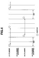
- Fig. 4 is a timing chart showing the ignition timing of selected cylinders upon malfunction of the variable valve timing mechanism.
-
- Referring to Fig. 1, there is schematically shown a system of the present invention, which is practically applied to an
internal combustion engine 1 for a motor vehicle. - The
engine 1 hascylinders 2 each having an upper portion serving as a combustion chamber. Eachcylinder 2 is equipped with intake andexhaust valves cylinder 2 is connected through an intake manifold to anair intake tube 5, and an exhaust port of eachcylinder 2 is connected through an exhaust manifold to anexhaust tube 6. Acatalytic converter 9 is connected to theexhaust tube 6 for purifying the exhaust gas from theengine 1. Anignition plug 7 is exposed to the combustion chamber of eachcylinder 2, and afuel injector 8 is exposed to the intake port of eachcylinder 2. - The intake and
exhaust valves electromagnetic actuators - As is seen from Fig. 2, each
actuator case 10a mounted to a cylinder head of theengine 1, a movingplate 12 axially movably disposed in thecase 10a and connected to astem 3a of thevalve first spring 13 arranged between an upper wall of thecase 10a and the movingplate 12 to bias the movingplate 12 downward, that is, in a direction to induce an open position of thevalve second spring 14 arranged between a lower wall of thecase 10a and the movingplate 12 to bias themoving plate 12 upward, that is, in a direction to induce a close position of thevalve first electromagnet 15 mounted on the lower wall of thecase 10a and asecond electromagnet 16 mounted beneath the upper wall of thecase 10a. It is to be noted that the movingplate 12 is made of a material, such as iron or the like, which is attracted by a magnetic force. - When
respective coils second electromagnets plate 12 is moved up to its uppermost position against the force of thefirst spring 13 allowing thevalve respective coils plate 12 is moved down to its lowermost position against the force of thesecond spring 14 allowing thevalve coils plate 12 is forced to take a neutral position by a balanced force produced by the first andsecond springs valve - Referring back to Fig. 1, the
air intake tube 5 is equipped with anair flow meter 21 to detect a flow rate of air flowing therethrough. An air pressure sensor may be used as theflow meter 21. Information signal from theair flow meter 21 is led to acontrol unit 20. Information signals from a crank-angle sensor 22, anaccelerator angle sensor 23, an enginecoolant temperature sensor 24 and an intakeair temperature sensor 25 are also led to thecontrol unit 20. As is known, engine rotation speed can be derived from the crank angle. In place of theaccelerator angle sensor 23, a throttle valve open degree sensor may be used, which detects the open degree of the throttle valve. -
Lift sensors electromagnetic actuators exhaust valves lift sensors control unit 20. - By processing the information signals led thereto, the
control unit 20 prepares or produces various instruction signals which are applied to eachfuel injector 8, eachignition plug 7 and adrive circuit 17 for theelectromagnetic actuators fuel injectors 8, theignition plugs 7 and theelectromagnetic actuators control unit 20. - As will be described in detail in the following, during operation of the
engine 1, operation of theelectromagnetic actuators control unit 20 judges that there has occurred a malfunction in theelectromagnetic actuators electromagnetic actuators ignition plug 7 andfuel injector 8 are rested for causing the associatedcylinder 2 to become inoperative, and at the same time, electromagnetic actuators (10, 11) for another cylinder (2) selected from the remaining cylinders and associated ignition plug (7) and fuel injector (8) are also rested causing the selected cylinder (2) to become inoperative. - It is to be noted that the selected cylinder (2) is a cylinder whose inoperative condition can cancel the unbalanced rotation of the
engine 1 which would be caused by the inoperative condition of thecylinder 2. That is, for example, a four cylinder in-line engine, upon detecting a failure of theelectromagnetic actuators cylinder 2 which is associated therewith and another cylinder (2) which has a symmetrical phase in operation to thecylinder 2 with respect to the stroke cycle are brought to an inoperative state. - In the following, the control of the
engine 1 at the time when a malfunction of theelectromagnetic actuators - At step S-1, judgment is carried out as to whether the
electromagnetic actuators lift sensors angle sensors 22 are used. That is, if the output from thelift sensor valve engine 1, it is judged that theactuators actuators actuators cylinder 2 which is associated with the abnormally operatingactuators - At step S-3, discrimination of another cylinder (2) is carried out, whose inoperative condition can cancel or at least minimize the unbalanced rotation of the
engine 1 which would be caused by the inoperative condition of thecylinder 2. - That is, in the four cylinder in-line engine, the cylinder (2) is a cylinder which has a symmetrical phase in operation to the
cylinder 2 with respect to the stroke cycle or firing order. If, as is seen from the timing chart of Fig. 4, the firing order of the engine is #1-#3-#4-#2 and theactuators second cylinder # 2 fail to operate normally, thesecond cylinder # 2 and thethird cylinder # 3 are brought to inoperative condition. In case of a six cylinder in-line engine, similar control is carried out. - If, in a V-6 engine, the firing order is for example #1-#2-#3-#4-#5-#6, three pairs "#1-#4", "#2-#5" and "#3-#6" can be selected for the inoperative condition.
- Referring back to the flowchart of Fig. 3, at step S-4, the operation of both the
cylinders 2 and (2) is stopped. For this stopping, current feeding from thedrive circuit 17 to theactuators cylinders 2 and (2) is stopped and at the same time, thefuel injectors 8 and that of the ignition plugs 7 for thecylinders 2 and (2) are also stopped. - Then, at step S-5, the amount of air/fuel mixture fed to each of the remaining cylinders is increased by directing all the air to only the remaining cylinders and increasing the fuel injected from the fuel injectors of the remaining cylinders, and at the same time, the ignition timing is adjusted in accordance with the mixture increase. With this step, power drop of the
engine 1 due to resting of the twocylinders 2 and (2) is suppressed or at least minimized. - As is mentioned hereinabove, in the four cylinder in-line engine, once a malfunction of the
electromagnetic actuators - If desired, a warning lamp may be provided on a meter panel of the vehicle, which is lighted upon occurrence of the malfunction of the
actuators - In the following, entire operation of the
engine 1 will be briefly described. - When
electromagnetic actuators engine 1 operates normally. - While, if, due to failure of the
electromagnetic actuators exhaust valve control unit 20 detects the failure based on the information signals from thelift sensors crank angle sensor 22 as has been described hereinabove. - Upon detecting the failure, the
control unit 20 stops operation of both acylinder 2 associated with theactuators cylinder 2 with respect to the stroke cycle. For stopping the operation of thecylinders 2 and (2), thecoils electromagnets cylinder 2 or (2) are deenergized to cause the associated intake andexhaust valves fuel injectors 8 and ignition plugs 7 are forced to take their rest state. - Then, the
control unit 20 increases the amount of air/fuel mixture fed to each of the remaining cylinders in the above-mentioned manner to suppress or at least minimize the power drop of theengine 1. - As is described hereinabove, upon failure of the variable valve timing mechanism (viz.,
electromagnetic actuators 10 and 11), acylinder 2 associated with the disabled mechanism and another cylinder (2) which has a symmetrical phase in operation to thecylinder 2 are brought to a stop or rest while carrying on operation of the remaining cylinders. Thus, as will be seen from Fig. 4, in the four (and also six and eight) cylinder engine, a so-called powerless ignition stroke (that is, an ignition stroke which fails to produce engine power) takes place at even intervals, which can reduce undesired engine vibration. That is, the powerless ignition stroke takes place at every 360° in crankshaft angle. - Upon resting of the two
cylinders 2 and (2), the amount of air/fuel mixture fed to the remaining cylinders is increased and thus power drop of theengine 1 is suppressed or at least minimized. - Although the above-description is directed to an
engine 1 usingelectromagnetic actuators - The entire contents of Japanese Patent Application P10-329399 (filed November 19, 1998) are incorporated herein by reference.
- Although the invention has been described above with reference to a certain embodiment of the invention, the invention is not limited to the embodiment described above. Various modifications and variations of the embodiment described above will occur to those skilled in the art, in light of the above teachings.
Claims (12)
- In an internal combustion engine equipped with a variable valve timing mechanism which variably controls operation timing of intake or exhaust valves of respective cylinders,A system for controlling the engine, comprising:a first unit which detects a failure of said variable valve timing mechanism;a second unit which discriminates a first cylinder which is associated with the variable valve timing mechanism in failure;a third unit which discriminates a second cylinder whose inoperative condition would cancel a possible unbalanced rotation of the engine which would be caused by an inoperative condition of said first cylinder;a fourth unit which causes said first and second cylinders to take the inoperative conditions; anda fifth unit which increases the amount of air/fuel mixture fed to the remaining cylinders.
- A system as claimed in Claim 1, in which said second cylinder discriminated by said third unit has a substantially symmetrical phase in operation to said first cylinder with respect to the stroke cycle of the engine.
- A system as claimed in Claim 1, in which said first unit detects the failure of the variable valve timing mechanism by analyzing the operation manner of said intake or exhaust valves with respect to a crank angle of the engine.
- A system as claimed in Claim 3, in which said first unit comprises:a lift sensor which produces an information signal representing open and close conditions of said intake or exhaust valves; anda crank angle sensor which produces an information signal representing the crank angle of the engine,
wherein the information signals from said lift sensor and said crank angle sensor are processed for detecting the failure of the variable valve timing mechanism. - A system as claimed in Claim 1, in which said variable valve timing mechanism comprises:a first electromagnet for causing each of the intake or exhaust valves to take an open position when energized;a second electromagnet for causing each of the intake or exhaust valves to a close position when energized;a first spring for biasing each of the intake or exhaust valves in a direction to induce the open position of the same; anda second spring for biasing each of the intake or exhaust valves in a direction to induce the close position of the same.
- A system as claimed in Claim 5, in which said fourth unit makes the variable valve timing mechanisms of said first and second cylinders inoperative so that the intake or exhaust valves of said first and second cylinders are kept in the slight open positions.
- A system as claimed in Claim 6, in which said fourth unit makes fuel injectors and ignition plugs of said first and second cylinders inoperative.
- A system as claimed in Claim 5, further comprising a sixth unit which adjusts ignition timing of the remaining cylinders in accordance with the increased amount of air/fuel mixture.
- In an internal combustion engine equipped with a variable valve timing mechanism which variably controls operation timing of intake or exhaust valves of respective cylinders,a method for controlling the engine, comprising:detecting a failure of said variable valve timing mechanism;discriminating a first cylinder which is associated with the variable valve timing mechanism in failure;discriminating a second cylinder whose inoperative condition would cancel a possible unbalanced rotation of the engine which would be caused by an inoperative condition of said first cylinder;causing said first and second cylinders to take the inoperative conditions; andincreasing the amount of air/fuel mixture fed to the remaining cylinders.
- A method as claimed in Claim 9, in which the detection of the failure of the variable valve timing mechanism is achieved by analyzing an information signal from a lift sensor, which senses open and close positions of one of the intake or exhaust valves, with respect to an information signal from an crank angle sensor which senses the crank angle of the engine.
- A method as claimed in Claim 10, in which the failure detection is made by judging whether or not the information signal issued from the lift sensor at the time when one of the intake or exhaust valves takes one of open and close positions is different from a reference information signal issued from the lift sensor at the corresponding time under normal operation of the engine.
- In an internal combustion engine including a plurality of cylinders, a variable valve timing mechanism for each cylinder, a fuel injector for each cylinder and an ignition plug for each cylinder,a system for controlling the engine, comprising:a first unit which detects a failure of the variable valve timing mechanism;a second unit which, upon detection of the failure by said first unit, selects a first cylinder of the cylinders, which is associated with the variable valve timing mechanism in failure;a third unit which, upon selection of the first cylinder by said second unit, selects a second cylinder of the cylinders, whose operation has a phase substantially symmetrical to that of the first cylinder with respect to the stroke cycle of the engine;a fourth unit which, upon selection of the second cylinder by said third unit, makes said first and second cylinders inoperative; anda fifth unit which, upon making the inoperative condition of said first and second cylinders, increases the amount of air/fuel mixture fed to the remaining cylinders.
Applications Claiming Priority (2)
| Application Number | Priority Date | Filing Date | Title |
|---|---|---|---|
| JP32939998 | 1998-11-19 | ||
| JP10329399A JP2000154740A (en) | 1998-11-19 | 1998-11-19 | Control device for variable valve engine |
Publications (2)
| Publication Number | Publication Date |
|---|---|
| EP1010865A1 true EP1010865A1 (en) | 2000-06-21 |
| EP1010865B1 EP1010865B1 (en) | 2004-07-07 |
Family
ID=18221005
Family Applications (1)
| Application Number | Title | Priority Date | Filing Date |
|---|---|---|---|
| EP99122512A Expired - Lifetime EP1010865B1 (en) | 1998-11-19 | 1999-11-11 | System and method for controlling internal combustion engine |
Country Status (4)
| Country | Link |
|---|---|
| US (1) | US6178934B1 (en) |
| EP (1) | EP1010865B1 (en) |
| JP (1) | JP2000154740A (en) |
| DE (1) | DE69918516T2 (en) |
Cited By (7)
| Publication number | Priority date | Publication date | Assignee | Title |
|---|---|---|---|---|
| EP1178199A3 (en) * | 2000-08-02 | 2002-12-18 | Ford Global Technologies, Inc. | System and method for mixture preparation control of an internal combustion engine |
| EP1394367A1 (en) * | 2002-08-26 | 2004-03-03 | Toyota Jidosha Kabushiki Kaisha | Control system of internal combustion engine |
| EP1361352A4 (en) * | 2001-02-14 | 2005-01-26 | Mikuni Kogyo Kk | DIRECT ACTING VALVE DRIVER FOR INTERNAL COMBUSTION ENGINE |
| US6953021B2 (en) | 2000-10-23 | 2005-10-11 | Honda Giken Kogyo Kabushiki Kaisha | Controller of hybrid vehicle |
| EP1232893A3 (en) * | 2001-02-20 | 2006-01-18 | Honda Giken Kogyo Kabushiki Kaisha | Control apparatus for hybrid vehicle with cylinder deactivation |
| WO2008037871A3 (en) * | 2006-09-25 | 2008-05-22 | Valeo Sys Controle Moteur Sas | Valve control system with malfunction detection |
| EP1611330A4 (en) * | 2003-01-22 | 2010-06-16 | Abraham E Karem | Fail-operational internal combustion engine |
Families Citing this family (40)
| Publication number | Priority date | Publication date | Assignee | Title |
|---|---|---|---|---|
| DE19918094A1 (en) * | 1999-04-21 | 2000-11-02 | Siemens Ag | Control system and method for operating an internal combustion engine |
| US6827051B2 (en) | 1999-12-03 | 2004-12-07 | Nissan Motor Co., Ltd. | Internal EGR quantity estimation, cylinder intake air quantity calculation, valve timing control, and ignition timing control |
| EP1707782A3 (en) | 1999-12-03 | 2011-07-06 | Nissan Motor Co., Ltd. | Control method for engine |
| JP3706335B2 (en) * | 2001-12-12 | 2005-10-12 | 本田技研工業株式会社 | Internal combustion engine failure determination device |
| JP4083647B2 (en) * | 2003-08-21 | 2008-04-30 | トヨタ自動車株式会社 | Intake air amount control device for internal combustion engine |
| US7128687B2 (en) * | 2004-03-19 | 2006-10-31 | Ford Global Technologies, Llc | Electromechanically actuated valve control for an internal combustion engine |
| US7031821B2 (en) * | 2004-03-19 | 2006-04-18 | Ford Global Technologies, Llc | Electromagnetic valve control in an internal combustion engine with an asymmetric exhaust system design |
| US7383820B2 (en) * | 2004-03-19 | 2008-06-10 | Ford Global Technologies, Llc | Electromechanical valve timing during a start |
| US7021289B2 (en) * | 2004-03-19 | 2006-04-04 | Ford Global Technology, Llc | Reducing engine emissions on an engine with electromechanical valves |
| US7559309B2 (en) * | 2004-03-19 | 2009-07-14 | Ford Global Technologies, Llc | Method to start electromechanical valves on an internal combustion engine |
| US7055483B2 (en) * | 2004-03-19 | 2006-06-06 | Ford Global Technologies, Llc | Quick starting engine with electromechanical valves |
| US6938598B1 (en) | 2004-03-19 | 2005-09-06 | Ford Global Technologies, Llc | Starting an engine with electromechanical valves |
| US7066121B2 (en) * | 2004-03-19 | 2006-06-27 | Ford Global Technologies, Llc | Cylinder and valve mode control for an engine with valves that may be deactivated |
| US7028650B2 (en) * | 2004-03-19 | 2006-04-18 | Ford Global Technologies, Llc | Electromechanical valve operating conditions by control method |
| US7079935B2 (en) * | 2004-03-19 | 2006-07-18 | Ford Global Technologies, Llc | Valve control for an engine with electromechanically actuated valves |
| US7140355B2 (en) * | 2004-03-19 | 2006-11-28 | Ford Global Technologies, Llc | Valve control to reduce modal frequencies that may cause vibration |
| US7240663B2 (en) * | 2004-03-19 | 2007-07-10 | Ford Global Technologies, Llc | Internal combustion engine shut-down for engine having adjustable valves |
| US7194993B2 (en) * | 2004-03-19 | 2007-03-27 | Ford Global Technologies, Llc | Starting an engine with valves that may be deactivated |
| US7107946B2 (en) * | 2004-03-19 | 2006-09-19 | Ford Global Technologies, Llc | Electromechanically actuated valve control for an internal combustion engine |
| US7017539B2 (en) * | 2004-03-19 | 2006-03-28 | Ford Global Technologies Llc | Engine breathing in an engine with mechanical and electromechanical valves |
| US7107947B2 (en) * | 2004-03-19 | 2006-09-19 | Ford Global Technologies, Llc | Multi-stroke cylinder operation in an internal combustion engine |
| US7165391B2 (en) | 2004-03-19 | 2007-01-23 | Ford Global Technologies, Llc | Method to reduce engine emissions for an engine capable of multi-stroke operation and having a catalyst |
| US7032545B2 (en) | 2004-03-19 | 2006-04-25 | Ford Global Technologies, Llc | Multi-stroke cylinder operation in an internal combustion engine |
| US7128043B2 (en) | 2004-03-19 | 2006-10-31 | Ford Global Technologies, Llc | Electromechanically actuated valve control based on a vehicle electrical system |
| US7555896B2 (en) * | 2004-03-19 | 2009-07-07 | Ford Global Technologies, Llc | Cylinder deactivation for an internal combustion engine |
| US7063062B2 (en) * | 2004-03-19 | 2006-06-20 | Ford Global Technologies, Llc | Valve selection for an engine operating in a multi-stroke cylinder mode |
| US7072758B2 (en) * | 2004-03-19 | 2006-07-04 | Ford Global Technologies, Llc | Method of torque control for an engine with valves that may be deactivated |
| US7032581B2 (en) * | 2004-03-19 | 2006-04-25 | Ford Global Technologies, Llc | Engine air-fuel control for an engine with valves that may be deactivated |
| US7082934B2 (en) * | 2004-08-24 | 2006-08-01 | Ford Global Technologies, Llc | Controlling spark for an engine with controllable valves |
| DE102004048704B4 (en) * | 2004-10-06 | 2008-05-29 | Siemens Ag | Method and device for controlling an internal combustion engine |
| KR100787542B1 (en) * | 2005-11-07 | 2007-12-21 | 엠에이엔 비앤드떠블유 디젤 에이/에스 | Excessive Torsional Vibration Reduction Method for Shaft Systems of Crosshead Type Two-stroke Internal Combustion Engines |
| US7284514B2 (en) * | 2006-02-13 | 2007-10-23 | Ford Global Technologies, Llc | Engine control system |
| US7578270B2 (en) * | 2007-04-13 | 2009-08-25 | Ford Global Technologies, Llc | Heat activated valve system |
| US8434436B2 (en) * | 2007-04-13 | 2013-05-07 | Ford Global Technologies, Llc | Electronically actuated valve system |
| JP4780351B2 (en) | 2008-04-01 | 2011-09-28 | トヨタ自動車株式会社 | Multi-cylinder engine |
| EP2372132B1 (en) * | 2008-12-26 | 2018-09-12 | Toyota Jidosha Kabushiki Kaisha | Device for controlling internal combustion engine using variable valve mechanism |
| GB2481432B (en) * | 2010-06-24 | 2016-06-29 | Gm Global Tech Operations Llc | Lubricating oil filter assembly |
| US9512749B2 (en) * | 2012-06-05 | 2016-12-06 | GM Global Technology Operations LLC | System and method for calibrating a valve lift sensor and evaluating a valve lift sensor and a hydraulic valve actuator |
| CN107489540B (en) * | 2016-06-09 | 2022-06-03 | 福特环球技术公司 | System and method for mitigating cylinder deactivation degradation |
| CN110541764B (en) * | 2018-05-29 | 2022-03-22 | 上海汽车集团股份有限公司 | Control method and device for improving NVH performance of parking of whole vehicle |
Citations (3)
| Publication number | Priority date | Publication date | Assignee | Title |
|---|---|---|---|---|
| EP0367448A1 (en) * | 1988-10-31 | 1990-05-09 | Isuzu Motors Limited | Valve control system for internal combustion engine |
| EP0777038A2 (en) * | 1995-01-27 | 1997-06-04 | Honda Giken Kogyo Kabushiki Kaisha | Control system for internal combustion engines |
| EP0915236A2 (en) * | 1997-11-10 | 1999-05-12 | Toyota Jidosha Kabushiki Kaisha | A power unit for a vehicle |
Family Cites Families (9)
| Publication number | Priority date | Publication date | Assignee | Title |
|---|---|---|---|---|
| DE3513105A1 (en) | 1985-04-12 | 1986-10-16 | Fleck, Andreas, 2000 Hamburg | ELECTROMAGNETIC ACTUATOR FOR GAS EXCHANGE VALVES |
| JP2770238B2 (en) * | 1989-06-15 | 1998-06-25 | 本田技研工業株式会社 | Failure detection method for valve timing switching control device of internal combustion engine |
| JP3043349B2 (en) * | 1989-12-12 | 2000-05-22 | 株式会社いすゞセラミックス研究所 | Electromagnetic force valve drive control device |
| US5190013A (en) * | 1992-01-10 | 1993-03-02 | Siemens Automotive L.P. | Engine intake valve selective deactivation system and method |
| JP3011016B2 (en) | 1994-05-24 | 2000-02-21 | トヨタ自動車株式会社 | Hydraulic valve device for internal combustion engine |
| US5596956A (en) * | 1994-12-16 | 1997-01-28 | Honda Giken Kogyo Kabushiki Kaisha | Electromagnetically driven valve control system for internal combustion engines |
| JP3309658B2 (en) * | 1995-08-25 | 2002-07-29 | トヨタ自動車株式会社 | Abnormality detection device for valve timing control device of internal combustion engine |
| JPH1047028A (en) | 1996-07-31 | 1998-02-17 | Suzuki Motor Corp | Control device for solenoid valve type engine |
| DE19733142C2 (en) * | 1997-07-31 | 2001-11-29 | Fev Motorentech Gmbh | Method for initiating the movement of a gas exchange valve actuated by an electromagnetic actuator |
-
1998
- 1998-11-19 JP JP10329399A patent/JP2000154740A/en active Pending
-
1999
- 1999-11-04 US US09/433,882 patent/US6178934B1/en not_active Expired - Fee Related
- 1999-11-11 EP EP99122512A patent/EP1010865B1/en not_active Expired - Lifetime
- 1999-11-11 DE DE69918516T patent/DE69918516T2/en not_active Expired - Fee Related
Patent Citations (3)
| Publication number | Priority date | Publication date | Assignee | Title |
|---|---|---|---|---|
| EP0367448A1 (en) * | 1988-10-31 | 1990-05-09 | Isuzu Motors Limited | Valve control system for internal combustion engine |
| EP0777038A2 (en) * | 1995-01-27 | 1997-06-04 | Honda Giken Kogyo Kabushiki Kaisha | Control system for internal combustion engines |
| EP0915236A2 (en) * | 1997-11-10 | 1999-05-12 | Toyota Jidosha Kabushiki Kaisha | A power unit for a vehicle |
Cited By (10)
| Publication number | Priority date | Publication date | Assignee | Title |
|---|---|---|---|---|
| EP1178199A3 (en) * | 2000-08-02 | 2002-12-18 | Ford Global Technologies, Inc. | System and method for mixture preparation control of an internal combustion engine |
| US6953021B2 (en) | 2000-10-23 | 2005-10-11 | Honda Giken Kogyo Kabushiki Kaisha | Controller of hybrid vehicle |
| EP1329620A4 (en) * | 2000-10-23 | 2006-06-14 | Honda Motor Co Ltd | Controller of hybrid vehicle |
| EP1361352A4 (en) * | 2001-02-14 | 2005-01-26 | Mikuni Kogyo Kk | DIRECT ACTING VALVE DRIVER FOR INTERNAL COMBUSTION ENGINE |
| EP1232893A3 (en) * | 2001-02-20 | 2006-01-18 | Honda Giken Kogyo Kabushiki Kaisha | Control apparatus for hybrid vehicle with cylinder deactivation |
| EP1394367A1 (en) * | 2002-08-26 | 2004-03-03 | Toyota Jidosha Kabushiki Kaisha | Control system of internal combustion engine |
| US6779508B2 (en) | 2002-08-26 | 2004-08-24 | Toyota Jidosha Kabushiki Kaisha | Control system of internal combustion engine |
| EP1611330A4 (en) * | 2003-01-22 | 2010-06-16 | Abraham E Karem | Fail-operational internal combustion engine |
| WO2008037871A3 (en) * | 2006-09-25 | 2008-05-22 | Valeo Sys Controle Moteur Sas | Valve control system with malfunction detection |
| US8256391B2 (en) | 2006-09-25 | 2012-09-04 | Valeo Systemes De Controle Moteur | Valve control system with malfunction detection |
Also Published As
| Publication number | Publication date |
|---|---|
| JP2000154740A (en) | 2000-06-06 |
| DE69918516D1 (en) | 2004-08-12 |
| EP1010865B1 (en) | 2004-07-07 |
| US6178934B1 (en) | 2001-01-30 |
| DE69918516T2 (en) | 2004-11-11 |
Similar Documents
| Publication | Publication Date | Title |
|---|---|---|
| EP1010865B1 (en) | System and method for controlling internal combustion engine | |
| US5765528A (en) | Idle speed control system for automotive internal combustion engine | |
| EP1153211B1 (en) | Failsafe control system and method for an electromagnetically driven valve | |
| US6431129B1 (en) | Method and system for transient load response in a camless internal combustion engine | |
| US6523504B2 (en) | Control system for controlling variable valve type internal combustion engine | |
| US8667835B2 (en) | Method and system for diagnosing cylinder valve activation/deactivation | |
| JP3043349B2 (en) | Electromagnetic force valve drive control device | |
| US5007382A (en) | Cycle changeable engine | |
| US6189512B1 (en) | Variable valve timing engine | |
| US6948358B2 (en) | Method for diagnosing incorrect valve lift adjustment in an internal combustion engine | |
| US6516777B2 (en) | Method and system for controlling internal combustion engine | |
| EP1104842B1 (en) | Intake air control system of engine | |
| US7520255B2 (en) | Control for an engine having a variable valve-driving unit | |
| US20060048746A1 (en) | Internal combustion engine capable of selectively resting certain cylinders during low-load operation, and method of using same | |
| US6213067B1 (en) | Control device for internal combustion engine | |
| US7188600B1 (en) | Internal combustion engine capable of selectively resting certain cylinders during low-load operation, and method of using same | |
| US5826551A (en) | Process and device for controlling the lift of an internal combustion engine valve | |
| EP1104850B1 (en) | System and method of controlling ignition timing in an engine with a variably operated intake valve | |
| EP1170489B1 (en) | Valve timing system for a camless engine | |
| JP4164614B2 (en) | Abnormality diagnosis device for electromagnetically driven valve of internal combustion engine | |
| GB2432017A (en) | Method of and control means for controlling switching of valves in a multi cylinder ic engine | |
| JP2001271664A (en) | Knock control device for internal combustion engine | |
| JP4080551B2 (en) | Control device for internal combustion engine | |
| JP2006299929A (en) | Control device for internal combustion engine | |
| JP2001271666A (en) | Internal combustion engine with variable valve mechanism |
Legal Events
| Date | Code | Title | Description |
|---|---|---|---|
| PUAI | Public reference made under article 153(3) epc to a published international application that has entered the european phase |
Free format text: ORIGINAL CODE: 0009012 |
|
| 17P | Request for examination filed |
Effective date: 19991111 |
|
| AK | Designated contracting states |
Kind code of ref document: A1 Designated state(s): DE FR GB |
|
| AX | Request for extension of the european patent |
Free format text: AL;LT;LV;MK;RO;SI |
|
| AKX | Designation fees paid |
Free format text: DE FR GB |
|
| GRAP | Despatch of communication of intention to grant a patent |
Free format text: ORIGINAL CODE: EPIDOSNIGR1 |
|
| GRAS | Grant fee paid |
Free format text: ORIGINAL CODE: EPIDOSNIGR3 |
|
| GRAA | (expected) grant |
Free format text: ORIGINAL CODE: 0009210 |
|
| AK | Designated contracting states |
Kind code of ref document: B1 Designated state(s): DE FR GB |
|
| REG | Reference to a national code |
Ref country code: GB Ref legal event code: FG4D |
|
| REF | Corresponds to: |
Ref document number: 69918516 Country of ref document: DE Date of ref document: 20040812 Kind code of ref document: P |
|
| PGFP | Annual fee paid to national office [announced via postgrant information from national office to epo] |
Ref country code: DE Payment date: 20041104 Year of fee payment: 6 |
|
| PGFP | Annual fee paid to national office [announced via postgrant information from national office to epo] |
Ref country code: FR Payment date: 20041109 Year of fee payment: 6 |
|
| PGFP | Annual fee paid to national office [announced via postgrant information from national office to epo] |
Ref country code: GB Payment date: 20041110 Year of fee payment: 6 |
|
| ET | Fr: translation filed | ||
| PLBE | No opposition filed within time limit |
Free format text: ORIGINAL CODE: 0009261 |
|
| STAA | Information on the status of an ep patent application or granted ep patent |
Free format text: STATUS: NO OPPOSITION FILED WITHIN TIME LIMIT |
|
| 26N | No opposition filed |
Effective date: 20050408 |
|
| PG25 | Lapsed in a contracting state [announced via postgrant information from national office to epo] |
Ref country code: GB Free format text: LAPSE BECAUSE OF NON-PAYMENT OF DUE FEES Effective date: 20051111 |
|
| PG25 | Lapsed in a contracting state [announced via postgrant information from national office to epo] |
Ref country code: DE Free format text: LAPSE BECAUSE OF NON-PAYMENT OF DUE FEES Effective date: 20060601 |
|
| GBPC | Gb: european patent ceased through non-payment of renewal fee |
Effective date: 20051111 |
|
| PG25 | Lapsed in a contracting state [announced via postgrant information from national office to epo] |
Ref country code: FR Free format text: LAPSE BECAUSE OF NON-PAYMENT OF DUE FEES Effective date: 20060731 |
|
| REG | Reference to a national code |
Ref country code: FR Ref legal event code: ST Effective date: 20060731 |