EP1010830A1 - Partitioning - Google Patents
Partitioning Download PDFInfo
- Publication number
- EP1010830A1 EP1010830A1 EP99310227A EP99310227A EP1010830A1 EP 1010830 A1 EP1010830 A1 EP 1010830A1 EP 99310227 A EP99310227 A EP 99310227A EP 99310227 A EP99310227 A EP 99310227A EP 1010830 A1 EP1010830 A1 EP 1010830A1
- Authority
- EP
- European Patent Office
- Prior art keywords
- grid
- wall
- tiles
- partitioning
- packing element
- Prior art date
- Legal status (The legal status is an assumption and is not a legal conclusion. Google has not performed a legal analysis and makes no representation as to the accuracy of the status listed.)
- Withdrawn
Links
- 238000000638 solvent extraction Methods 0.000 title claims description 34
- 238000012856 packing Methods 0.000 claims abstract description 26
- 238000009434 installation Methods 0.000 claims abstract description 20
- 239000000853 adhesive Substances 0.000 claims abstract description 11
- 230000001070 adhesive effect Effects 0.000 claims abstract description 11
- 238000000034 method Methods 0.000 claims description 9
- 230000000717 retained effect Effects 0.000 claims description 4
- 238000005192 partition Methods 0.000 abstract 1
- 238000010276 construction Methods 0.000 description 2
- 229920003023 plastic Polymers 0.000 description 2
- 239000004033 plastic Substances 0.000 description 2
- 239000002390 adhesive tape Substances 0.000 description 1
- 230000005540 biological transmission Effects 0.000 description 1
- 230000000903 blocking effect Effects 0.000 description 1
- 230000014759 maintenance of location Effects 0.000 description 1
- 239000000463 material Substances 0.000 description 1
- 239000002184 metal Substances 0.000 description 1
- 230000002093 peripheral effect Effects 0.000 description 1
- 238000002360 preparation method Methods 0.000 description 1
- 230000001681 protective effect Effects 0.000 description 1
- 230000002441 reversible effect Effects 0.000 description 1
- 238000004904 shortening Methods 0.000 description 1
Images


Classifications
-
- E—FIXED CONSTRUCTIONS
- E04—BUILDING
- E04B—GENERAL BUILDING CONSTRUCTIONS; WALLS, e.g. PARTITIONS; ROOFS; FLOORS; CEILINGS; INSULATION OR OTHER PROTECTION OF BUILDINGS
- E04B9/00—Ceilings; Construction of ceilings, e.g. false ceilings; Ceiling construction with regard to insulation
- E04B9/008—Ceilings; Construction of ceilings, e.g. false ceilings; Ceiling construction with regard to insulation with means for connecting partition walls or panels to the ceilings
Definitions
- This invention relates to partitioning and is particularly concerned with partitioning installations and methods of installing partitioning.
- the invention is also concerned with elements for use in these installations and methods.
- a partitioning installation in which tiles of a suspended-ceiling hang from a supporting grid to define the ceiling surface below the grid, wherein the top of a partitioning wall of the installation extends to the ceiling surface to abut the tiles and is secured to the grid through gaps between the tiles, and each such gap is occupied by a packing element that is sandwiched between the grid and the top of the wall at the ceiling surface.
- the wall may be screwed to the grid through the packing element, and the tiles may be retained peripherally within respective apertures of the grid to hang part way down through it.
- a method of installing partitioning in which tiles of a suspended-ceiling are hung from a supporting grid to define the ceiling surface below the grid, wherein the top of a partitioning wall of the installation is extended to the ceiling surface to abut the tiles and is secured to the grid through gaps between the tiles, and each such gap is occupied by a packing element that is sandwiched between the grid and the top of the wall at the ceiling surface.
- the packing element may be affixed adhesively to the grid prior to extension of the wall to the ceiling surface, and the packing element may have an adhesive backing for this purpose. Furthermore, the wall may be screwed to the grid through the packing element.
- a packing element for use between a supporting grid of a suspended-ceiling and the top of a partitioning wall which abuts tiles hung from the grid, comprises an elongate body having an adhesive backing for affixing the element to the grid prior to attachment of the wall to the grid.
- One or more holes for screws may be provided through the body of the element, and the body may have a transverse notch to facilitate division of the element into two parts of unequal length.
- a partitioning wall 1 is installed to divide office or other space within a building, from floor 2 to ceiling 3.
- the ceiling 3 is of a suspended construction in which tiles 4 are retained within the apertures 5 between metal supports 6 of I-section, of a rectangular grid 7.
- the tiles 4 have peripheral lips 8 that, as illustrated in Figure 2, rest on the lower flanges 9 of the supports 6 so that each tile 4 hangs part way down through the grid 7, filling its respective aperture 5.
- the exposed surface of the ceiling 3 is accordingly formed by the under-faces 10 of the tiles 4, with narrow gaps 11 running between them beneath the supports 6.
- the partitioning wall 1 would be taken up into the ceiling-surface through the tiles 4 to butt onto the underside of the flanges 9 of the grid-supports 6 for screw-fixing to them.
- This practice involves cutting the tiles accurately so that they abut the wall without leaving unsightly gaps on either side of the wall along its length. Cutting the tiles hampers installation and adds to cost, as well as requiring the cut tiles to be replaced if and when the partitioning wall is removed.
- the tiles 4 are not cut and the partitioning wall 1 (indicated in broken line) is taken up only to the ceiling surface formed by the under-sides 10 of the tiles 4.
- the wall 1 therefore does not enter the gaps 11, and although the gaps 11 are narrow enough to go largely unnoticed across the wide expanse of the ceiling, they break very distinctly the continuity of the narrow junction line along which the wall 1 butts onto the ceiling tiles 4. More especially, the gaps 11 allow transmission of sound from one side of the wall 1 to the other, and may reveal unsightly screw-fixings by which the wall 1 is held to the supports 6.
- packing elements 12 of the form shown in Figures 3 to 6, within the gaps 11. The elements 12 are secured between the top of the wall 1 and the supports 6 where the wall 1 is crossed by the grid 7 so as to fill-in the gaps 11 at those locations.
- each packing element 12 has an elongate body 13 of plastics material and of rectangular cross-section and carries an adhesive strip 14.
- the adhesive strip 14 is a length of double-sided adhesive tape with one side adhered to the upper-surface 15 of the body 13.
- the other adhesive side of the tape-strip 14 is covered by a protective film (not shown) that is removed before the element 12 is pushed up into the gap 11 where the wall 1 is to cross the ceiling 3.
- the element 12 is pushed up into the gap 11 to bring the adhesive strip 14 hard on to the support 6 in that location. This ensures that the element 12 adheres firmly to the grid 7 in preparation for placing and fixing of the wall 1.
- each element 12 is of a thickness to ensure that its under-surface 16 is flush with the under-faces 10 of the tiles 4, and is of a length corresponding to the width of the wall 1 to be installed. More especially, the length is sufficient to ensure that the element 12 occupies fully, or at least to a substantial extent, the gap 11 immediately above the header-channel 17 of the wall 1.
- the ends 18 of the element 12 are preferably, as illustrated, flush with the side-surfaces 19 of the channel 17 so as to obviate any break of the junction line of the surfaces 19 with the ceiling tiles 4.
- a working tolerance of this nature is required where, as well may be the case, one (or more) of the grid-supports 6 is not truly in-line and there is accordingly a degree of misalignment between the wall 1 and the grid 7.
- the element 12 in the present case is chosen to be of a length suitable for installation of a partitioning wall of the maximum thickness normally used. Provision is however made for shortening the element 12 where a thinner wall is involved, and in this respect a transverse notch 20 ( Figures 3 and 5) in the under-surface 16 facilitates dividing of the body 13 into two parts 21 and 22, one part for use in the job on hand and the other for retention for possible future use.
- the overall length of the element 12 may be 100 mm, and in this case the longer part 21 may be used where a wall-thickness of some 75 mm is involved, and the part 22 where the wall-thickness is some 25 mm.
- the part 22 for example, for glass-silicon-jointed fully-glazed partitioning, where the wall-thickness is 45 mm.
- the gap 11 will not be filled fully in this latter case, it will be still be occupied to a substantial extent and adequately enough for practical purposes in blocking the gap.
- the header-channel 17 can be screwed in place sandwiching the element 12 between it and the support 6.
- a slotted hole 23 and a hole 24 are provided through the parts 21 and 22, respectively, for the screw or screws used.
- the hole 24 may be used in this respect as well as the slotted hole 23 when the whole length of element 12 is utilised.
- the elements 12 may be provided in one or more ranges of size for use with varying forms of partitioning and suspended-ceiling constructions and styles. Also, the element may be of a modified form as illustrated in Figures 8 to 11 for use where a reversible header-channel is used at the top of the partitioning wall.
- the packing element 26 in this case is also of plastics and carries a double-sided adhesive strip 27 for adhering to the underside of the support 6 as illustrated in Figure 8.
- the element 26 is for use where, as in Figure 8, an H-section header-channel 28 is utilised at the top of a partitioning wall 29.
- the element 26 has a hollow shank 30 so that when it is adhered to the support 6, it projects downwardly between the tiles 4 to stand on the web 31 of the channel 28 when the longer flanges 32 of the channel 28 abut the under-faces 10 of the tiles 4. Screws (not shown) which are secured through the web 31 into the support 6 pass through the hollow shank 30 and thereby hold the channel 28 firmly clamped to the grid 7.
- the shank 30 can be shortened by removal of a lower portion 33. This enables the element 26 to be adapted to use of the header-channel 28 turned over for its shorter flanges 34 to abut the under-faces 10 of the tiles 4.
Landscapes
- Engineering & Computer Science (AREA)
- Architecture (AREA)
- Physics & Mathematics (AREA)
- Electromagnetism (AREA)
- Civil Engineering (AREA)
- Structural Engineering (AREA)
- Finishing Walls (AREA)
Abstract
Elongate packing elements (12) fill gaps (11) between
tiles (4) of a suspended-ceiling where the gaps (11) are
traversed by a partition wall (1) that abuts the under-faces
(10) of the tiles (4). Each element (12) has an
adhesive backing (14), and before the wall (1) is
extended to the ceiling during installation, the element
(12) is affixed within its gap (11) to an I-section
support (6) of a rectangular grid (7) through which the
tiles (4) are hung. The header-channel (17) of the wall
(1) is screwed to the support (6) through the element
(12), sandwiching the element (12) between them to at
least partially block the gap (11) there. A notch (20)
in the element (12) allows it to be divided for use with
walls of different thicknesses, and an alternative
packing element (26) for use with an H-section header-channel
(28) can be shortened for use with the channel
(28) reversed.
Description
- This invention relates to partitioning and is particularly concerned with partitioning installations and methods of installing partitioning. The invention is also concerned with elements for use in these installations and methods.
- According to one aspect of the present invention there is provided a partitioning installation in which tiles of a suspended-ceiling hang from a supporting grid to define the ceiling surface below the grid, wherein the top of a partitioning wall of the installation extends to the ceiling surface to abut the tiles and is secured to the grid through gaps between the tiles, and each such gap is occupied by a packing element that is sandwiched between the grid and the top of the wall at the ceiling surface.
- The wall may be screwed to the grid through the packing element, and the tiles may be retained peripherally within respective apertures of the grid to hang part way down through it.
- According to another aspect of the present invention there is provided a method of installing partitioning in which tiles of a suspended-ceiling are hung from a supporting grid to define the ceiling surface below the grid, wherein the top of a partitioning wall of the installation is extended to the ceiling surface to abut the tiles and is secured to the grid through gaps between the tiles, and each such gap is occupied by a packing element that is sandwiched between the grid and the top of the wall at the ceiling surface.
- The packing element may be affixed adhesively to the grid prior to extension of the wall to the ceiling surface, and the packing element may have an adhesive backing for this purpose. Furthermore, the wall may be screwed to the grid through the packing element.
- According to a further aspect of the invention a packing element for use between a supporting grid of a suspended-ceiling and the top of a partitioning wall which abuts tiles hung from the grid, comprises an elongate body having an adhesive backing for affixing the element to the grid prior to attachment of the wall to the grid.
- One or more holes for screws may be provided through the body of the element, and the body may have a transverse notch to facilitate division of the element into two parts of unequal length.
- Two partitioning installations and methods, together with packing elements for use therein, all in accordance with the present invention, will now be described, by way of example, in which:
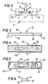
- Figure 1 is a perspective view from above, partly broken away, of a first of the two partitioning installations according to the invention;
- Figure 2 is a sectional side elevation illustrating support of tiles of a suspended-ceiling that forms part of the partitioning installation of Figure 1;
- Figures 3 to 6 are, respectively, a side elevation, a plan view from above, a plan view from below and an end-elevation of a form of packing element according to the present invention used in the partitioning installation of Figure 1;
- Figure 7 is a cross-sectional view of part of the partitioning wall and suspended-ceiling of Figure 1, showing the packing element of Figures 3 to 6 in place;
- Figure 8 is a cross-sectional view corresponding to that of Figure 7, of the second partitioning installation according to the invention; and
- Figures 9 to 11 are, respectively, a plan view from above, a plan view from below and an end-elevation of a packing element forming part of the partitioning installation of Figure 8.
-
- Referring to Figures 1 and 2, a partitioning
wall 1 is installed to divide office or other space within a building, fromfloor 2 to ceiling 3. The ceiling 3 is of a suspended construction in whichtiles 4 are retained within theapertures 5 between metal supports 6 of I-section, of arectangular grid 7. Thetiles 4 haveperipheral lips 8 that, as illustrated in Figure 2, rest on thelower flanges 9 of thesupports 6 so that eachtile 4 hangs part way down through thegrid 7, filling itsrespective aperture 5. The exposed surface of the ceiling 3 is accordingly formed by the under-faces 10 of thetiles 4, withnarrow gaps 11 running between them beneath thesupports 6. - With known installation-practice the partitioning
wall 1 would be taken up into the ceiling-surface through thetiles 4 to butt onto the underside of theflanges 9 of the grid-supports 6 for screw-fixing to them. This practice involves cutting the tiles accurately so that they abut the wall without leaving unsightly gaps on either side of the wall along its length. Cutting the tiles hampers installation and adds to cost, as well as requiring the cut tiles to be replaced if and when the partitioning wall is removed. - In accordance with the present invention, and as illustrated more especially in Figure 2, the
tiles 4 are not cut and the partitioning wall 1 (indicated in broken line) is taken up only to the ceiling surface formed by the under-sides 10 of thetiles 4. Thewall 1 therefore does not enter thegaps 11, and although thegaps 11 are narrow enough to go largely unnoticed across the wide expanse of the ceiling, they break very distinctly the continuity of the narrow junction line along which thewall 1 butts onto the ceiling tiles 4. More especially, thegaps 11 allow transmission of sound from one side of thewall 1 to the other, and may reveal unsightly screw-fixings by which thewall 1 is held to thesupports 6. The problem is overcome according to the invention in the present case usingpacking elements 12 of the form shown in Figures 3 to 6, within thegaps 11. Theelements 12 are secured between the top of thewall 1 and thesupports 6 where thewall 1 is crossed by thegrid 7 so as to fill-in thegaps 11 at those locations. - Referring to Figures 3 to 6, each
packing element 12 has anelongate body 13 of plastics material and of rectangular cross-section and carries anadhesive strip 14. Theadhesive strip 14 is a length of double-sided adhesive tape with one side adhered to the upper-surface 15 of thebody 13. The other adhesive side of the tape-strip 14 is covered by a protective film (not shown) that is removed before theelement 12 is pushed up into thegap 11 where thewall 1 is to cross the ceiling 3. Theelement 12 is pushed up into thegap 11 to bring theadhesive strip 14 hard on to thesupport 6 in that location. This ensures that theelement 12 adheres firmly to thegrid 7 in preparation for placing and fixing of thewall 1. - As illustrated in Figure 7, each
element 12 is of a thickness to ensure that its under-surface 16 is flush with the under-faces 10 of thetiles 4, and is of a length corresponding to the width of thewall 1 to be installed. More especially, the length is sufficient to ensure that theelement 12 occupies fully, or at least to a substantial extent, thegap 11 immediately above the header-channel 17 of thewall 1. Theends 18 of theelement 12 are preferably, as illustrated, flush with the side-surfaces 19 of thechannel 17 so as to obviate any break of the junction line of thesurfaces 19 with theceiling tiles 4. However, there is inevitably a degree of tolerance available from the practical point of view in the relationship between the length of theelement 12 used and the thickness of thewall 1. A working tolerance of this nature is required where, as well may be the case, one (or more) of the grid-supports 6 is not truly in-line and there is accordingly a degree of misalignment between thewall 1 and thegrid 7. - The acceptability of tolerance in location of the
element 12 within thegap 11, aids in the setting out of the partitioning, in that placing of theelement 12 on thegrid 7 does not have to be very precise. In this respect, the tolerance available will in general enable theelements 12 to be positioned on thegrid 7 simply by measuring off distances alongindividual supports 6. The necessity experienced with present installation-practice for straight lines to be drawn (normally in chalk) across the ceiling, can thus be avoided. - The
element 12 in the present case is chosen to be of a length suitable for installation of a partitioning wall of the maximum thickness normally used. Provision is however made for shortening theelement 12 where a thinner wall is involved, and in this respect a transverse notch 20 (Figures 3 and 5) in the under-surface 16 facilitates dividing of thebody 13 into twoparts element 12 may be 100 mm, and in this case thelonger part 21 may be used where a wall-thickness of some 75 mm is involved, and thepart 22 where the wall-thickness is some 25 mm. It is also possible to use thepart 22, for example, for glass-silicon-jointed fully-glazed partitioning, where the wall-thickness is 45 mm. Although thegap 11 will not be filled fully in this latter case, it will be still be occupied to a substantial extent and adequately enough for practical purposes in blocking the gap. - Once an element 12 (or
part grid 7 in each location where thewall 1 is to traverse thesupports 6, the header-channel 17 can be screwed in place sandwiching theelement 12 between it and thesupport 6. To facilitate this, and as shown in Figures 3 and 5, aslotted hole 23 and ahole 24 are provided through theparts hole 24 may be used in this respect as well as theslotted hole 23 when the whole length ofelement 12 is utilised. - The
elements 12 may be provided in one or more ranges of size for use with varying forms of partitioning and suspended-ceiling constructions and styles. Also, the element may be of a modified form as illustrated in Figures 8 to 11 for use where a reversible header-channel is used at the top of the partitioning wall. - Referring to Figures 8 to 11, the
packing element 26 in this case is also of plastics and carries a double-sidedadhesive strip 27 for adhering to the underside of thesupport 6 as illustrated in Figure 8. Theelement 26 is for use where, as in Figure 8, an H-section header-channel 28 is utilised at the top of a partitioningwall 29. In particular, theelement 26 has ahollow shank 30 so that when it is adhered to thesupport 6, it projects downwardly between thetiles 4 to stand on theweb 31 of thechannel 28 when the longer flanges 32 of thechannel 28 abut the under-faces 10 of thetiles 4. Screws (not shown) which are secured through theweb 31 into thesupport 6 pass through thehollow shank 30 and thereby hold thechannel 28 firmly clamped to thegrid 7. - The
shank 30 can be shortened by removal of alower portion 33. This enables theelement 26 to be adapted to use of the header-channel 28 turned over for itsshorter flanges 34 to abut the under-faces 10 of thetiles 4.
Claims (12)
- A partitioning installation in which tiles of a suspended-ceiling hang from a supporting grid to define the ceiling surface below the grid, wherein the top of a partitioning wall of the installation extends to the ceiling surface to abut the tiles and is secured to the grid through gaps between the tiles, and each such gap is occupied by a packing element that is sandwiched between the grid and the top of the wall at the ceiling surface.
- A partitioning installation according to Claim 1 wherein the wall is screwed to the grid through the packing element.
- A partitioning installation according to Claim 1 or Claim 2 wherein the tiles are retained peripherally within respective apertures of the grid to hang part way down through the grid.
- A partitioning installation according to any one of Claims 1 to 3 wherein the packing element has an adhesive backing affixing it to the grid.
- A method of installing partitioning in which tiles of a suspended-ceiling are hung from a supporting grid to define the ceiling surface below the grid, wherein the top of a partitioning wall of the installation is extended to the ceiling surface to abut the tiles and is secured to the grid through gaps between the tiles, and each such gap is occupied by a packing element that is sandwiched between the grid and the top of the wall at the ceiling surface.
- A method according to Claim 5 wherein the packing element is affixed adhesively to the grid prior to extension of the wall to the ceiling surface.
- A method according to Claim 6 wherein the packing element has an adhesive backing for affixing it to the grid.
- A method according to any one of Claims 5 to 7 wherein the tiles are retained peripherally within respective apertures of the grid to hang part way down through the grid.
- A method according to any one of Claims 5 to 8 wherein the wall is screwed to the grid through the packing element.
- A packing element for use between a supporting grid of a suspended-ceiling and the top of a partitioning wall which abuts tiles hung from the grid, wherein said element comprises an elongate body having an adhesive backing for affixing the element to the grid prior to attachment of the wall to the grid.
- A packing element according to Claim 10 wherein there are one or more holes for screws through said body.
- A packing element according to Claim 10 or Claim 11 wherein said body has a transverse notch to facilitate division of the element into two parts of unequal length.
Applications Claiming Priority (2)
| Application Number | Priority Date | Filing Date | Title |
|---|---|---|---|
| GBGB9827744.5A GB9827744D0 (en) | 1998-12-17 | 1998-12-17 | Partitioning |
| GB9827744 | 1998-12-17 |
Publications (1)
| Publication Number | Publication Date |
|---|---|
| EP1010830A1 true EP1010830A1 (en) | 2000-06-21 |
Family
ID=10844366
Family Applications (1)
| Application Number | Title | Priority Date | Filing Date |
|---|---|---|---|
| EP99310227A Withdrawn EP1010830A1 (en) | 1998-12-17 | 1999-12-17 | Partitioning |
Country Status (2)
| Country | Link |
|---|---|
| EP (1) | EP1010830A1 (en) |
| GB (2) | GB9827744D0 (en) |
Cited By (1)
| Publication number | Priority date | Publication date | Assignee | Title |
|---|---|---|---|---|
| EP2196590A1 (en) | 2008-12-10 | 2010-06-16 | Rockwool International A/S | Suspended ceiling structure connected to a construction element and method of mounting a construction element to a suspended ceiling structure |
Citations (4)
| Publication number | Priority date | Publication date | Assignee | Title |
|---|---|---|---|---|
| US4073108A (en) * | 1974-04-25 | 1978-02-14 | Williams Arthur C | Method and apparatus for rigidly interconnected ceiling and wall construction |
| US4232068A (en) * | 1979-01-02 | 1980-11-04 | Hoh Thomas L | Shim |
| US4912899A (en) * | 1989-03-30 | 1990-04-03 | Plasker John C | Drywall edge reveal trim strip |
| FR2710089A1 (en) * | 1993-09-17 | 1995-03-24 | Hopenko Marie Francoise | Acoustically insulating anti-lifting block |
Family Cites Families (6)
| Publication number | Priority date | Publication date | Assignee | Title |
|---|---|---|---|---|
| FR1400389A (en) * | 1964-01-17 | 1965-05-28 | Materiaux Reunis | Assembly device for prefabricated panels |
| BE766106A (en) * | 1970-04-27 | 1971-09-16 | Callegari Christian | PARTITIONS CONSISTING OF PANELS SUBJECT TO THE BUILDING USING PROFILES AND PARTITION FIXING DEVICE |
| US3848385A (en) * | 1970-06-12 | 1974-11-19 | Nat Ceiling Corp | Modular ceiling construction |
| US3986314A (en) * | 1974-12-23 | 1976-10-19 | Moeller Wolfgang W | Ceiling assembly with removable partition walls |
| NL1000288C1 (en) * | 1995-05-03 | 1996-06-03 | Nevima Bv | Method for connecting a partition wall or a suspended ceiling to a building construction and means for applying this method. |
| GB9704655D0 (en) * | 1997-03-06 | 1997-04-23 | Ecomax Acoustics Ltd | Method and system for supporting partitions and particularly partitioning boards intended to provide acoustic insulation |
-
1998
- 1998-12-17 GB GBGB9827744.5A patent/GB9827744D0/en not_active Ceased
-
1999
- 1999-12-17 EP EP99310227A patent/EP1010830A1/en not_active Withdrawn
- 1999-12-17 GB GB9929942A patent/GB2345304A/en not_active Withdrawn
Patent Citations (4)
| Publication number | Priority date | Publication date | Assignee | Title |
|---|---|---|---|---|
| US4073108A (en) * | 1974-04-25 | 1978-02-14 | Williams Arthur C | Method and apparatus for rigidly interconnected ceiling and wall construction |
| US4232068A (en) * | 1979-01-02 | 1980-11-04 | Hoh Thomas L | Shim |
| US4912899A (en) * | 1989-03-30 | 1990-04-03 | Plasker John C | Drywall edge reveal trim strip |
| FR2710089A1 (en) * | 1993-09-17 | 1995-03-24 | Hopenko Marie Francoise | Acoustically insulating anti-lifting block |
Cited By (1)
| Publication number | Priority date | Publication date | Assignee | Title |
|---|---|---|---|---|
| EP2196590A1 (en) | 2008-12-10 | 2010-06-16 | Rockwool International A/S | Suspended ceiling structure connected to a construction element and method of mounting a construction element to a suspended ceiling structure |
Also Published As
| Publication number | Publication date |
|---|---|
| GB9827744D0 (en) | 1999-02-10 |
| GB9929942D0 (en) | 2000-02-09 |
| GB2345304A (en) | 2000-07-05 |
Similar Documents
| Publication | Publication Date | Title |
|---|---|---|
| US5848512A (en) | Structural member for wall assembly | |
| US8733721B2 (en) | Board mount | |
| US3707819A (en) | Decking system | |
| US3397495A (en) | Partition wall with yieldable cap members | |
| US20050102952A1 (en) | Construction method | |
| US4297823A (en) | Hollow wall repair device | |
| US4698944A (en) | Flush finishing metal door frame | |
| CA2040577A1 (en) | Mounting template | |
| MXPA97007901A (en) | Set of adjusting hanger | |
| US3731447A (en) | Wallboard attachment | |
| US4442152A (en) | Marker member | |
| JPH10219887A (en) | Box mounting method to lightweight type steel, its device, and gauge tool | |
| GB2345304A (en) | Partitioning system with packers to fill gaps between ceiling and wall | |
| US20050115196A1 (en) | Stucco lath with stud spacing indicators | |
| US20090094924A1 (en) | Sectioning scheme applied to two or four foot cross tee members associated with a ceiling grid system and for resizing both the cross tee and associated ceiling tile for installation at a border cut location between a main tee and parallel extending wall angle | |
| JP3035269B2 (en) | Box mounting equipment and mounting equipment for construction materials | |
| CA2568444A1 (en) | Joist support | |
| US8955277B1 (en) | Device for raising drywall off of a flooring surface and method of use | |
| US5383317A (en) | Shaft wall cavity extension | |
| CA1304214C (en) | Channel utility notch | |
| US5598638A (en) | Electrical stick | |
| US4584807A (en) | Composite soffit of plastic material and furring strips | |
| GB2210914A (en) | Support device for services | |
| DE59507198D1 (en) | CONCRETE STEEL STRIPS FOR SURFACE CONCRETE CONSTRUCTIONS | |
| JP3606845B2 (en) | Ceiling surround and ceiling structure using the same |
Legal Events
| Date | Code | Title | Description |
|---|---|---|---|
| PUAI | Public reference made under article 153(3) epc to a published international application that has entered the european phase |
Free format text: ORIGINAL CODE: 0009012 |
|
| AK | Designated contracting states |
Kind code of ref document: A1 Designated state(s): AT BE CH CY DE DK ES FI FR GB GR IE IT LI LU MC NL PT SE |
|
| AX | Request for extension of the european patent |
Free format text: AL;LT;LV;MK;RO;SI |
|
| 17P | Request for examination filed |
Effective date: 20001220 |
|
| AKX | Designation fees paid |
Free format text: AT BE CH CY DE DK ES FI FR GB GR IE IT LI LU MC NL PT SE |
|
| STAA | Information on the status of an ep patent application or granted ep patent |
Free format text: STATUS: THE APPLICATION HAS BEEN WITHDRAWN |
|
| 18W | Application withdrawn |
Effective date: 20021216 |