EP1009696B1 - Pneumatic device for the transporting of mechanical pieces, and apparatus comprising such device - Google Patents
Pneumatic device for the transporting of mechanical pieces, and apparatus comprising such device Download PDFInfo
- Publication number
- EP1009696B1 EP1009696B1 EP98940228A EP98940228A EP1009696B1 EP 1009696 B1 EP1009696 B1 EP 1009696B1 EP 98940228 A EP98940228 A EP 98940228A EP 98940228 A EP98940228 A EP 98940228A EP 1009696 B1 EP1009696 B1 EP 1009696B1
- Authority
- EP
- European Patent Office
- Prior art keywords
- piston
- recess
- casing
- thrust
- pneumatic
- Prior art date
- Legal status (The legal status is an assumption and is not a legal conclusion. Google has not performed a legal analysis and makes no representation as to the accuracy of the status listed.)
- Expired - Lifetime
Links
Images

Classifications
-
- B—PERFORMING OPERATIONS; TRANSPORTING
- B65—CONVEYING; PACKING; STORING; HANDLING THIN OR FILAMENTARY MATERIAL
- B65G—TRANSPORT OR STORAGE DEVICES, e.g. CONVEYORS FOR LOADING OR TIPPING, SHOP CONVEYOR SYSTEMS OR PNEUMATIC TUBE CONVEYORS
- B65G47/00—Article or material-handling devices associated with conveyors; Methods employing such devices
- B65G47/74—Feeding, transfer, or discharging devices of particular kinds or types
- B65G47/90—Devices for picking-up and depositing articles or materials
- B65G47/91—Devices for picking-up and depositing articles or materials incorporating pneumatic, e.g. suction, grippers
- B65G47/911—Devices for picking-up and depositing articles or materials incorporating pneumatic, e.g. suction, grippers with air blasts producing partial vacuum
Definitions
- the present invention relates to a pneumatic device for picking up and releasing substantially flat objects, according to the preamble of claim 1.
- the invention relates to an apparatus for picking up and releasing shims in appropriate seats in the cylinder head of an internal combustion engine, comprising a support body and a plurality of pneumatic pick up devices coupled to the support body.
- European patent application EP-A-0273057 discloses a head having the above-mentioned features of a pneumatic device according to the invention.
- the head includes a body with a suction pad for engaging with the top of the objectto be transported and an air passage.
- the air passage is connected to a pressure reducing source that generates the suction force.
- the air passage is connected to a source of compressed air that blows the object off the suction pad and/or pulls a weight against the object surface.
- the "Venturi tube” is an instrument for measuring the velocity of a fluid in a conduit, that consists of a tube with two truncated cones joined together at the minor bases.
- a fluid, flowing through the instrument increases its velocity in the portion with converging cross-section and decreases it in the portion with diverging cross-section and in consideration of the fact that the pressure is inversely proportional to the square of velocity (as stated in the Bernoulli principle), the velocity variation generates an opposite variation in pressure, that is higher at the input and at the output of the tube and is lower at the choke defined by the area of conjunction between the two truncated cones.
- the devices that exploit this principle and are mainly utilized for picking up and transporting flat, delicate and light weight objects generally comprise an element with a substantially plane surface and a centrally located hole connected to a conduit for blowing compressed air.
- the device is moved towards the object to be picked up so that the plane surface faces a surface of the object, thereby creating, by means of the two surfaces, a choke like the one in the "Venturi tube".
- the air flows out of the hole and into the choke at a high velocity, thus, according to the Bernoulli principle, the increase of the air velocity between the surface of the device and that of the object induces a depression between the two surfaces with respect to the atmospheric air pressure on the opposite surface of the object.
- the pressure differential between the two surfaces becomes sufficiently high to overcome the force of gravity, the object can be picked up by the device, and released by the latter when the air flow is cut off.
- U.S. patent 4,969,676 describes a manually operated device of the above described type for transporting silicon wafers for integrated circuits, that comprises a disc with a flat surface and a central air passage, and centering elements coupled at the periphery of the disc.
- Pneumatic devices of this type are also utilized in the automotive industry, more specifically in apparatuses operating in automatic assembly lines for picking up and transporting appropriately thick shims and inserting them in respective recesses at the valve side of bucket type tappets of internal combustion engines, thus attaining the required amount of clearance between the cams of the camshaft and the valves.
- Similar apparatuses comprise a certain number of devices, or "pneumatic heads", that pick up the shims in the formerly described manner at a selection station, transport and release them in the recesses of the associated bucket type tappets at the valve side.
- the heads are equipped with lateral limiting devices that have the purpose of centering the shims, hence permitting their correct insertion in the associated bucket type tappets.
- the lateral limiting devices apply transversal forces to the shim thereby causing, when the head retracts, the at least partial displacement of the shim out of the bucket type tappet recess.
- Object of the present invention is to provide a pneumatic pick up and release device that overcomes the limits of the known apparatuses, and in particular ensures a proper release of the objects that have been picked up.
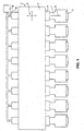
- Figure 1 schematically shows an apparatus 1 for inserting a series of shims 3 in appropriate seats at the valve side of associated bucket type tappets of a cylinder head of an internal combustion engine, not shown in the figures.
- shims 3 as already known, are specifically selected in order to define the proper amount of clearance between each cam of the camshaft and its associated valve.
- the apparatus 1 comprises a support body 5 and a set of pneumatic pick up devices, or pneumatic heads, 7 coupled thereto for picking up, transporting and inserting shims 3 in the seats of the associated bucket type tappets.
- Each head 7 defines a longitudinal geometric axis and is coupled with body 5 by means of a resilient type coupling, featured in a known way that is schematically shown and identified by reference number 4 in figure 1, that allows limited reciprocal longitudinal displacements, in. the range of a few millimeters, according to the direction indicated by arrows 6.
- body 5 may have guides and slides, also per se known and not illustrated in the drawings, that enable the set of heads 7 to perform the displacements required for transporting the shims 3 from the pick up area to the seats where they are released, for example according to the directions indicated by arrows 8.
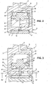
- Each pneumatic head 7 has a casing 9, of a substantially cylindrical shape, with a larger terminal portion 11 that comprises a closure plate 37 for defining a transversal, substantially plane, end surface 47.
- the terminal portion 11, i.e. specifically the end surface 47 has a rim 13 and a certain number of longitudinal centering overhangs; or teeth, 14 arranged along rim 13 (as an example only, the device shown in the figures has four teeth).
- the terminal portion 11 comprises a cylindrical recess 21 and a pneumatic circuit including a conduit 19, housed in casing 9 and communicating with recess 21 , and a source of compressed air, identified by reference number 20 in figure 1, connected to conduit 19.
- the closure plate 37 has a cylindrical through hole 45 communicating with the cylindrical recess 21 and substantially aligned along the longitudinal axis of head 7 .
- a thrust mechanism includes a piston 25 that can longitudinally slide within the interior of cylindrical recess 21 and has cylindrical portions with different diameter that define transversal plane limit stop surfaces 32 and 40 for contacting internal plane surfaces 33 and 41 of recess 21 for limiting-the stroke of piston 25 in either direction, and transversal, oppositely arranged, thrust surface 34 and retraction surface 42.
- a pin 35 is coupled to, for example screwed into, piston 25 and arranged substantially along the longitudinal axis of head 7.
- the diameter of pin 35 is smaller than that of the cylindrical hole 45 for the purpose of allowing the flow of compressed air through the formerly mentioned hole even when pin 35 is partially housed therein.
- the thrust mechanism comprises a compression spring 31 , arranged between the internal plane surface 33 of the cylindrical recess 21 and the transversal thrust surface 34 , that urges pin 35 towards the exterior of casing 9 , by protruding from hole 45 .
- the compressed air injected into the cylindrical recess 21 through conduit 19, acts upon the transversal retraction surface 42 for urging piston 25, and thus pin 35, towards the interior, in a retracted position (as shown in figure 2).
- the same compressed air flows out of recess 21 by passing through hole 45.
- the apparatus operates in the following way.
- Body 5 of apparatus 1 is displaced towards a pick up area, not shown in the figures, where the shims 3 to be inserted in the seats of the bucket type tappets have been suitably arranged.
- the shims 3 have different thickness and are selected on the basis of previous checkings and measurement takings performed, for example, on the cylinder head and the camshaft, for determining the amount of clearance that it is desired to achieve between the cams and their associated valves.
- the end surfaces 47 of the pneumatic heads 7 are moved towards the shims 3 until contact is made. Then, ejection of compressed air from source 20 is started.
- each head 7 the compressed air flows -by passing through conduit 19- into recess 21 and urges piston 25 towards the interior in the retracted position, opposing the thrust applied by compression spring 31 (figure 2). Moreover, air flows through hole 45 of closure plate 37, comes out of the same hole 45 and moves in a path limited by end surface 47 and shim 3, thereby lifting head 7 with respect to shim 3 of an amount in the range of a tenth of a millimeter, thanks to the resilient type coupling 4 between head 7 and body 5 , and flows, at a high velocity owing to the "Venturi tube” effect, substantially along radial directions, within the small amount of space existing between surface 47 and the surface of the shim 3 to be picked up.
- teeth 14 contribute to center shims 3 with respect to the associated end surfaces 47.
- pins 35 are urged by springs 31 to continue to exert their action on shims 3 for a short stroke, that is sufficient for keeping the shims 3 properly positioned in seats 10 and opposing the effect of possible undesired transversal forces among some of the teeth 14 and the associated shims 3, that could tend to displace the shims 3 out of seats 10, upon the retraction of the associated heads 7.
- the device according to the invention guarantees a proper and stable insertion of the shims 3 in their associated seats 10 of the bucket type tappets.
- An embodiment like the one herein described and illustrated is particularly advantageous in that it enables to simultaneously perform with just a single pneumatic .circuit and a single control- both the pick up (and the release) of shims 3 by exploiting the Bernoulli principle and the retraction (and the release) of the thrust mechanism. More specifically, as described in the foregoing description, the same compressed air flow ejected from source 20 and that passes through conduit 19 induces both the depression -that enables to pick up the shims- and the release of piston 25. The stopping of the formerly mentioned air flow causes the release of the shims and simultaneously the actuation of the thrust mechanisms.
- one or more pneumatic devices according to the invention can be utilized in apparatuses that have an entirely different structure with respect to the one that has been illustrated in an extremely schematic way in figure 1 for picking up and releasing substantially flat pieces that may have an entirely different shape and function with respect to those of the herein described and illustrated shims.
Landscapes
- Engineering & Computer Science (AREA)
- Mechanical Engineering (AREA)
- Valve-Gear Or Valve Arrangements (AREA)
- Air Transport Of Granular Materials (AREA)
Description
Claims (5)
- Pneumatic device for picking up and releasing substantially flat objects, the device defining a longitudinal geometric axis and comprisinga pin (35), coupled to the piston (25) and arranged along a longitudinal direction, the pin (35) being adapted for protruding from the casing (9) through the through hole (45) in said thrust position of the piston, characterized in that the piston (25) comprises at least a transversal retraction surface (42) for cooperating with the compressed air that flows from the source through conduit (19) for keeping the piston (25) in said retracted position.a substantially cylindrical shaped casing (9), that includes a terminal portion (11) with a transversal plane end surface (47), a longitudinal through hole (45) traversing said surface (47), and a recess (21) communicating with said through hole (45),a pneumatic circuit comprising a source of compressed air (20) and a conduit (19), at least partially housed in the casing (9) and communicating with the recess (21), for the flow of compressed air from the source (20) to said through hole (45), anda thrust mechanism including a piston (25), housed in said recess (21) of the casing (9), movable therein between a retracted and a thrust position along a longitudinal direction, and
- A device according to claim 1, wherein the thrust mechanism comprises a compression spring (31), arranged between surfaces (33,34) of casing (9) and piston (25), for urging said piston (25) towards said thrust position.
- A device according to claim 2, wherein said recess (21) has a substantially cylindrical shape and defines internal plane surfaces (33,41), the piston (25) comprising transversal plane limit stop surfaces (32,40) for cooperating with the internal plane surfaces of recess (21) for limiting the displacements of piston (25) and defining said retracted and thrust positions.
- A device according to claim 3, wherein said terminal portion (11) of casing (9) comprises a rim (13) and a plurality of longitudinal centering overhangs (14).
- Apparatus for picking up and releasing shims (3) in appropriate seats in the cylinder head of an internal combustion engine, comprising a support body (5) and a plurality of pneumatic pick up devices (7), according to one of claims from 1 to 4, coupled to said support body by means of a resilient coupling (4).
Applications Claiming Priority (3)
| Application Number | Priority Date | Filing Date | Title |
|---|---|---|---|
| IT97BO000524A IT1294178B1 (en) | 1997-09-03 | 1997-09-03 | PNEUMATIC DEVICE FOR THE TRANSPORT OF MECHANICAL PARTS, AND EQUIPMENT INCLUDING SUCH DEVICE. |
| ITBO970524 | 1997-09-03 | ||
| PCT/EP1998/004389 WO1999011549A1 (en) | 1997-09-03 | 1998-07-15 | Pneumatic device for the transporting of mechanical pieces, and apparatus comprising such device |
Publications (2)
| Publication Number | Publication Date |
|---|---|
| EP1009696A1 EP1009696A1 (en) | 2000-06-21 |
| EP1009696B1 true EP1009696B1 (en) | 2001-11-14 |
Family
ID=11342498
Family Applications (1)
| Application Number | Title | Priority Date | Filing Date |
|---|---|---|---|
| EP98940228A Expired - Lifetime EP1009696B1 (en) | 1997-09-03 | 1998-07-15 | Pneumatic device for the transporting of mechanical pieces, and apparatus comprising such device |
Country Status (4)
| Country | Link |
|---|---|
| EP (1) | EP1009696B1 (en) |
| DE (1) | DE69802551T2 (en) |
| IT (1) | IT1294178B1 (en) |
| WO (1) | WO1999011549A1 (en) |
Families Citing this family (2)
| Publication number | Priority date | Publication date | Assignee | Title |
|---|---|---|---|---|
| AT410540B (en) * | 2001-06-21 | 2003-05-26 | Ctr Carinthian Tech Res Ag | GRIPPERS FOR HANDLING THIN PLATES |
| CN116198960B (en) * | 2023-04-24 | 2023-09-29 | 中科摩通(常州)智能制造股份有限公司 | Turnover equipment for manual rechecking of heat pump and working method of turnover equipment |
Family Cites Families (8)
| Publication number | Priority date | Publication date | Assignee | Title |
|---|---|---|---|---|
| US4657470A (en) * | 1984-11-15 | 1987-04-14 | Westinghouse Electric Corp. | Robotic end effector |
| JPH0795070B2 (en) * | 1986-06-10 | 1995-10-11 | 東ソー株式会社 | Adsorption heads for transporting reaction cups used in biochemical reaction measuring devices |
| IT1214033B (en) * | 1987-02-03 | 1990-01-05 | Carlomagno Giovanni Maria | PROCEDURE AND DEVICE FOR EXERCISING FORCES ON GLASS SHEETS, IN PARTICULAR AT HIGH TEMPERATURE |
| US4969676A (en) | 1989-06-23 | 1990-11-13 | At&T Bell Laboratories | Air pressure pick-up tool |
| FR2652334B1 (en) * | 1989-09-22 | 1992-01-10 | Recif Sa | NOZZLE FOR VACUUM PIPETTE BODY IN PARTICULAR. |
| JPH0786049B2 (en) * | 1990-06-18 | 1995-09-20 | 本田技研工業株式会社 | Shim supply method to work |
| US5385441A (en) * | 1993-11-23 | 1995-01-31 | Motorola, Inc. | Method and apparatus for picking and placing an article |
| US5456510A (en) * | 1994-04-28 | 1995-10-10 | Universal Instruments Corporation | Vacuum nozzle with a push-off device |
-
1997
- 1997-09-03 IT IT97BO000524A patent/IT1294178B1/en active IP Right Grant
-
1998
- 1998-07-15 EP EP98940228A patent/EP1009696B1/en not_active Expired - Lifetime
- 1998-07-15 WO PCT/EP1998/004389 patent/WO1999011549A1/en not_active Ceased
- 1998-07-15 DE DE69802551T patent/DE69802551T2/en not_active Expired - Fee Related
Also Published As
| Publication number | Publication date |
|---|---|
| DE69802551D1 (en) | 2001-12-20 |
| DE69802551T2 (en) | 2002-06-27 |
| WO1999011549A1 (en) | 1999-03-11 |
| ITBO970524A1 (en) | 1999-03-03 |
| ITBO970524A0 (en) | 1997-09-03 |
| IT1294178B1 (en) | 1999-03-22 |
| EP1009696A1 (en) | 2000-06-21 |
Similar Documents
| Publication | Publication Date | Title |
|---|---|---|
| US4768475A (en) | Valve mechanism for an automotive engine | |
| US4950011A (en) | Tool for precisely positioning a workpiece | |
| CN103237962B (en) | Sliding cam system with sliding groove and stop | |
| JP2788381B2 (en) | Automatic device sending device for handler | |
| US4678073A (en) | Apparatus and methods for handling bulk arrays of articles | |
| KR102206672B1 (en) | Removable valve bridge and valve actuation system including the same | |
| US5682847A (en) | Valve actuating device for engine | |
| US4431103A (en) | Engine positioning device in engine test device | |
| CN108350765A (en) | Valve train carrier sub-assembly | |
| US5366353A (en) | Air valve with bleed feature to inhibit icing | |
| JP2000002748A (en) | IC suction device, IC transport device and IC test device using the same | |
| US4787346A (en) | Valve operating apparatus for an internal combustion engine | |
| GB2130550A (en) | Robot hand | |
| EP1009696A1 (en) | Pneumatic device for the transporting of mechanical pieces, and apparatus comprising such device | |
| EP0282136A2 (en) | Gripping device | |
| US8740506B2 (en) | Positioning apparatus | |
| JP2646616B2 (en) | Transfer parts sorting device | |
| KR101972343B1 (en) | Ceramics picker assembly | |
| US4485914A (en) | Variable drive pin projection mechanism for a belt sprocket drive wheel | |
| CN101946293A (en) | Comprise the device of electromagnet and electromagnet plate and comprise the valve actuator of this device | |
| JPH0516048A (en) | Positioning device | |
| JPH06194200A (en) | Carrier for assembling, inspection and calibration for mass air-flow sensor | |
| JPH08292228A (en) | IC device testing equipment | |
| US5072505A (en) | Method for assembling a retainer ring onto an article | |
| US5075944A (en) | Apparatus for compressing a retainer ring to assembly size |
Legal Events
| Date | Code | Title | Description |
|---|---|---|---|
| PUAI | Public reference made under article 153(3) epc to a published international application that has entered the european phase |
Free format text: ORIGINAL CODE: 0009012 |
|
| 17P | Request for examination filed |
Effective date: 20000315 |
|
| AK | Designated contracting states |
Kind code of ref document: A1 Designated state(s): DE GB IT |
|
| GRAG | Despatch of communication of intention to grant |
Free format text: ORIGINAL CODE: EPIDOS AGRA |
|
| GRAG | Despatch of communication of intention to grant |
Free format text: ORIGINAL CODE: EPIDOS AGRA |
|
| GRAH | Despatch of communication of intention to grant a patent |
Free format text: ORIGINAL CODE: EPIDOS IGRA |
|
| 17Q | First examination report despatched |
Effective date: 20010405 |
|
| GRAH | Despatch of communication of intention to grant a patent |
Free format text: ORIGINAL CODE: EPIDOS IGRA |
|
| GRAA | (expected) grant |
Free format text: ORIGINAL CODE: 0009210 |
|
| AK | Designated contracting states |
Kind code of ref document: B1 Designated state(s): DE GB IT |
|
| REF | Corresponds to: |
Ref document number: 69802551 Country of ref document: DE Date of ref document: 20011220 |
|
| REG | Reference to a national code |
Ref country code: GB Ref legal event code: IF02 |
|
| PLBE | No opposition filed within time limit |
Free format text: ORIGINAL CODE: 0009261 |
|
| STAA | Information on the status of an ep patent application or granted ep patent |
Free format text: STATUS: NO OPPOSITION FILED WITHIN TIME LIMIT |
|
| 26N | No opposition filed | ||
| PGFP | Annual fee paid to national office [announced via postgrant information from national office to epo] |
Ref country code: GB Payment date: 20040621 Year of fee payment: 7 |
|
| PGFP | Annual fee paid to national office [announced via postgrant information from national office to epo] |
Ref country code: DE Payment date: 20040809 Year of fee payment: 7 |
|
| PG25 | Lapsed in a contracting state [announced via postgrant information from national office to epo] |
Ref country code: IT Free format text: LAPSE BECAUSE OF NON-PAYMENT OF DUE FEES Effective date: 20050715 Ref country code: GB Free format text: LAPSE BECAUSE OF NON-PAYMENT OF DUE FEES Effective date: 20050715 |
|
| PG25 | Lapsed in a contracting state [announced via postgrant information from national office to epo] |
Ref country code: DE Free format text: LAPSE BECAUSE OF NON-PAYMENT OF DUE FEES Effective date: 20060201 |
|
| GBPC | Gb: european patent ceased through non-payment of renewal fee |
Effective date: 20050715 |