EP1009633B1 - A spray dampening device for a printing press - Google Patents
A spray dampening device for a printing press Download PDFInfo
- Publication number
- EP1009633B1 EP1009633B1 EP98904500A EP98904500A EP1009633B1 EP 1009633 B1 EP1009633 B1 EP 1009633B1 EP 98904500 A EP98904500 A EP 98904500A EP 98904500 A EP98904500 A EP 98904500A EP 1009633 B1 EP1009633 B1 EP 1009633B1
- Authority
- EP
- European Patent Office
- Prior art keywords
- spray
- casing
- roller
- valves
- mounting bracket
- Prior art date
- Legal status (The legal status is an assumption and is not a legal conclusion. Google has not performed a legal analysis and makes no representation as to the accuracy of the status listed.)
- Expired - Lifetime
Links
- 239000007921 spray Substances 0.000 title claims description 125
- 238000007639 printing Methods 0.000 title claims description 12
- 239000007788 liquid Substances 0.000 claims description 12
- 238000007789 sealing Methods 0.000 claims description 9
- 238000005507 spraying Methods 0.000 claims description 4
- 230000004048 modification Effects 0.000 description 4
- 238000012986 modification Methods 0.000 description 4
- 239000000463 material Substances 0.000 description 3
- 239000003595 mist Substances 0.000 description 3
- 238000004140 cleaning Methods 0.000 description 1
- 238000004891 communication Methods 0.000 description 1
- 238000010276 construction Methods 0.000 description 1
- 230000008878 coupling Effects 0.000 description 1
- 238000010168 coupling process Methods 0.000 description 1
- 238000005859 coupling reaction Methods 0.000 description 1
- 238000010616 electrical installation Methods 0.000 description 1
- 239000002699 waste material Substances 0.000 description 1
Images



Classifications
-
- B—PERFORMING OPERATIONS; TRANSPORTING
- B41—PRINTING; LINING MACHINES; TYPEWRITERS; STAMPS
- B41F—PRINTING MACHINES OR PRESSES
- B41F7/00—Rotary lithographic machines
- B41F7/20—Details
- B41F7/24—Damping devices
- B41F7/30—Damping devices using spraying elements
Definitions
- the present invention relates to a spray dampening device for spraying fountain solution on a rotating roller in a printing press, comprising a spray casing to be fixedly mounted to the printing press frame in the vicinity of the roller and a number of spray valves for spraying fountain solution on the roller through the spray casing.
- a device of the kind defined above is disclosed in US-A-5 595 116, which is regarded as the closest prior art.
- the spray casing is divided into two parts, of which a forward one is fixedly mounted to the printing press frame and a rearward one is provided with the spray valves and can be position adjusted in relation to the forward one by a complicated arrangement.
- a spray dampening device is an integrated unit, comprising a spray beam with the spray valves and the spray casing, mounted in the printing press frame.
- a better solution is according to the invention attained in that a separate spray beam, in which the spray valves are arranged, at each end is attached to the spray casing by means of a mounting bracket, allowing longitudinal adjustment of the spray beam and thus the spray valves in relation to the fixed spray casing.
- the spray dampening device can also be made totally enclosed but still be easy to mount, dismount and service.
- the mounting bracket may preferably be attached to the spray beam, in a first embodiment, or to the spray casing, in a second embodiment, by means of screws or the like extending through at least two oblong bracket holes, which are substantially parallel to a line normal to the roller, so that an easy adjustment of the position of the spray beam in relation to the spray casing may be performed.
- the spray casing By its fixed mounting the spray casing may be arranged so close to the roller that very little fountain solution leaves it inadvertently in the form of undesired mist, whereas the design with the mounting brackets for mounting the spray beam with the valves to the spray casing enables a very simple and accurate position adjustment of the spray beam and thus the valves in relation to the casing and the roller.
- the mounting bracket is pivotably and releasably attached to the spray casing, in the first embodiment, or to the spray beam, in the second embodiment, by means of two attachment devices at opposite sides of the line normal to the roller.
- the spray beam may be pivoted to either side or even be released completely. It will hereby be very easy to mount, clean and service the beam and its valves and nozzles.
- the beam can be mounted at either side of the roller or with the connection devices to the left or the right without any design changes.
- attachment devices are spring-biassed pins, which extend into corresponding bores in the ends of the spray casing or the spray beam, respectively. Further, each pin may preferably be locked in a position retracted out of engagement with its bore.
- the spray casing may be of a rather simple construction and can for example be made of a plastic material.
- the valve nozzles of the spray beam valves may extend into the valve casing through circular openings, which are provided with flexible sealing means. In this way the fountain solution sprayed through the nozzles will not appear as undesired mist in the printing press and is prevented from reaching the spray beam with its different details and electrical installations.
- the sealing means may also fulfil its sealing task after every adjustment of the spray beam position.
- valves were mechanically attached to the beam at predetermined locations.
- the valves were connected by means of hoses and couplings.
- a far better solution is according to the invention attained in that rigid pipes are utilized instead of the hoses.
- the distances between the valves in the spray beam are hereby determined by the length of the liquid pipes, which are simply sealingly inserted into the valves. No separate attachment for the valves is hereby needed, which makes it possible to mount the spray beam at a lower cost and much easier to service the beam, which can be detached from the fixedly mounted spray casing without any difficulty.
- the spray beam is symmetric and may be mounted in any position without any modification.
- Fig 1 is a top view of a portion of a first embodiment of a spray dampening device according to the invention
- Fig 2 is a front view, partly in section, of a spray beam forming a part of the spray dampening device according to Fig 1
- Fig 3 is a sectional view through the spray dampening device according to Fig 1 arranged at a roller to be sprayed
- Fig 4 is an end view of the spray dampening device according to Fig 1
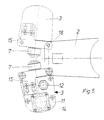
- Fig 5 is a view corresponding to Fig 4 and illustrates an important aspect of the invention
- Fig 6 is a sectional view through a second embodiment of a spray dampening device according to the invention
- Fig 7 is an end view of the spray dampening device according to Fig 6.
- a first embodiment of a spray dampening device according to the invention will first be described under reference to Figs 1-5, whereupon a second and preferred embodiment will be described under reference to Figs 6 and 7.
- a rotating roller 1 (Fig 3) in a printing press is to be evenly sprayed or damped with fountain solution by means of a spray dampening device.
- Such a device according to the invention generally includes a spray casing 2 and a spray beam 3.
- the spray casing 2 may be made of a plastic material and normally has a length corresponding to the length of the printing press roller 1 and is generally closed except at its side facing the roller. It is fixedly mounted close to the roller 1, so that a minimum of the liquid sprayed within it leaks out to the environment in the form of undesired mist.
- the mounting appears in Fig 1 and consists simply of a rod 4 attached to the spray casing 2 and to an attachment 5 in the printing press frame 6.
- the casing 2 In its wall opposite the roller 1, the casing 2 is provided with a number of preferably circular openings for spray valves 7 to be described.
- the spray beam 3 is attached to the spray casing 2 in a way to be described.
- An important feature of the invention is that there is no attachment of the spray beam 3 to the printing press frame 6; to the contrary, the spray beam is fully suspended by the spray casing 2 fixedly mounted to the frame.
- the spray beam 3 is shown in section in Fig 3.
- Spray valves 7 are inserted into the spray beam 3 at intervals, preferably equidistantly.
- the distances between the valves 7 shall correspond to the distances between the mentioned openings in the spray casing 2, or vice versa.
- the spray nozzles 7' of the valves 7 extend into the spray casing 2, and there is preferably a flexible bellows 8 between each nozzle 7' and the corresponding spray casing opening for sealingly preventing communication from the interior of the spray casing 2.
- each rigid liquid pipe 10 determines the distance between each consecutive spray valve 7, which is not otherwise attached in the spray beam 3.
- a gable 11 with an external liquid connector 12 to the internal pipes 10 and valves 7.
- the gable 11 is attached to spray beam itself by means of screws 13 (Fig 4).
- the spray valves 7 are electrically controlled magnet valves. External electrical connection is provided by an electrical connector 14 on the gable 11, and there is room in the spray beam 3 for electric wires and the like.
- a mounting bracket 15 (best shown in Fig 4) is attached to each spray beam gable 11 by means of two screws 16 extending through oblong holes 15' in the bracket 15 and into the gable 11.
- the holes 15' extend generally parallel to a central line 19, which is normal to the roller 1 and extends through the spray beam 3, the spray casing 2 and the roller 1.
- the mounting bracket 15 is also releasably attached to the spray casing 2 by means of two spring-biassed pins 17.
- Each such pin 17 is axially movably attached to the bracket 15 and is biassed by a spring (not shown) into engagement with a bore 18 (Fig 5) in the end of the spray casing 2. By turning the pin 17 it may be locked in a position retracted in the bracket 15 out of engagement with the spray casing bore 18.
- a further advantage of the descibed design is that the spray beam 3 - as is illustrated in Fig 5 - can be pivoted in two directions for easy access to the valve nozzles 7' for service and the like.
- the same device may accordingly without modifications be used for mounting at either side of a roller 1 - to the left as shown in Fig 3 or to the right. Also, the spray beam 3 may easily be completely removed.
- FIGs 6 and 7 A second and preferred embodiment of a spray dampening device according to the invention is shown in Figs 6 and 7.
- the first and second embodiments have very much in common, and accordingly corresponding parts have corresponding reference numerals with the addition of an "A" for the second embodiment.
- a spray casing 2A a spray beam 3A, a mounting rod 4A, a spray valve 7A, a spray nozzle 7A', a through hole 9A, a gable 11A, an external liquid connector 12A, screws 13A, an electrical connector 14A, a mounting bracket 15A, an oblong hole 15A', a screw 16A, spring-biassed pins 17A, bores 18A, and a central line 19A.
- the mounting bracket 15A at each side of the device is mounted to the spray beam gable 11A by means of the spring-biassed pins 17A, enabling the spray beam 3A to be pivoted in either direction (as illustrated in Fig 5 for the first embodiment) or to be removed completely.
- the mounting bracket 15A is towards its opposite end provided with the oblong hole 15A' for the screw 16A, which is to be fastened in the spray casing 2A, when the correct position of the spray beam 3A and thus the valves 7A therein has been determined.
- the mounting bracket 15A is also provided with a second oblong hole 15A" for the mounting rod 4A to pass through. In this way the mounting rod 4A can act as a support and guide for the mounting bracket 15A.
- One of the advantages with the described arrangement of the mounting bracket 15A in the second embodiment is that it will be possible to arrange appropriate drainage holes 20A (Fig 6) in the spray casing 2A. Two such holes 20A may be provided in each end of the spray casing 2A, and normally only one of the four holes is left unplugged for collection of waste fountain solution from the spray casing 2A.
- a second modification in relation to the first embodiment is the arrangement at the liquid connector 12A for supplying fountain solution to the valves 7A (in the way depicted in Figs 1 and 2 for the first embodiment).
- the liquid connector 12A passes non-centrally through an oblong inset 21A mounted in an oblong hole 11A' in the spray beam gable 11A. In this way only one version of the gable 11A is needed irrespective of the mounting position of the spray beam 3A.
- valve 7A is provided with a sealing ring 22A, which has to be mounted in an appropriate position on the valve 7A in relation to the mounting position of the spray beam 3A on the spray casing 2A.
- sealing ring 22A Cooperating with the sealing ring 22A is a flexible sealing sleeve 23A of a rubbery material mounted in the hole of the spray casing 2A.
Landscapes
- Engineering & Computer Science (AREA)
- Mechanical Engineering (AREA)
- Rotary Presses (AREA)
Description
Fig 1 is a top view of a portion of a first embodiment of a spray dampening device according to the invention,
Fig 2 is a front view, partly in section, of a spray beam forming a part of the spray dampening device according to Fig 1,
Fig 3 is a sectional view through the spray dampening device according to Fig 1 arranged at a roller to be sprayed,
Fig 4 is an end view of the spray dampening device according to Fig 1,
Fig 5 is a view corresponding to Fig 4 and illustrates an important aspect of the invention,
Fig 6 is a sectional view through a second embodiment of a spray dampening device according to the invention, and
Fig 7 is an end view of the spray dampening device according to Fig 6.
Claims (10)
- A spray dampening device for spraying fountain solution on a rotating roller (1) in a printing press, comprising a spray casing (2; 2A) to be fixedly mounted to the printing press frame (6) in the vicinity of the roller and a number of spray valves (7; 7A) for spraying fountain solution on the roller through the spray casing, a separate spray beam (3; 3A), in which the valves (7; 7A) are arranged, at each end being attached to the spray casing (2; 2A) by means of a mounting bracket (15; 15A), wherein said mounting brackets allowing longitudinal adjustment of the spray beam and thus the spray valves in relation to the fixed spray casing.
- A device according to claim 1, characterized in that the mounting bracket (15) is attached to the spray beam (3) by means of screws (16) or the like extending through at least two oblong bracket holes (15'), which are substantially parallel to a line (19) normal to the roller (1).
- A device according to claim 1, characterized in that the mounting bracket (15) is pivotably and releasably attached to the spray casing (2) by means of two attachment devices (17) at opposite sides of the line (19) normal to the roller (1).
- A device according to claim 1, characterized in that the mounting bracket (15A) is attached to the spray casing (2A) by means of a screw (16A) or the like extending through an oblong bracket hole (15A'), which is substantially parallel to a line (19A) normal to the roller.
- A device according to claim 1, characterized in that the mounting bracket (15A) is pivotably and releasably attached to the spray beam (3A) by means of two attachment devices (17; 17A) at opposite sides of the line (19A) normal to the roller.
- A device according to claim 3 or 5, characterized in that the attachment devices are spring-biassed pins (17; 17A), which extend into corresponding bores (18; 18A) in the ends of the spray casing (2) or the spray beam (3A), respectively.
- A device according to claim 6, characterized in that the pins (17; 17A) may be locked in a position retracted out of engagement with the bores (18; 18A).
- A device according to claim 1, characterized in that the valve nozzles (7'; 7A') extend into the spray casing (2; 2A) through openings, which preferably are circular and which are provided with flexible sealing means (8; 23A), each having a hole for its valve nozzle.
- A device according to claim 1, characterized in that the distances between the valves (7; 7A) in the spray beam (3; 3A) are determined by the lengths of liquid pipes (10) inserted into the valves.
- A device according to claim 9, characterized in that an external liquid connector (12A) to the liquid pipes (10) passes through an oblong inset (21A) mounted in a oblong hole (11A') in a spray beam gable (11A).
Priority Applications (1)
| Application Number | Priority Date | Filing Date | Title |
|---|---|---|---|
| EP02021090A EP1273440B1 (en) | 1997-02-17 | 1998-02-16 | A spray dampening device for a printing press |
Applications Claiming Priority (3)
| Application Number | Priority Date | Filing Date | Title |
|---|---|---|---|
| SE9700535A SE518402C2 (en) | 1997-02-17 | 1997-02-17 | Spray humidifier for a printing press |
| SE9700535 | 1997-02-17 | ||
| PCT/SE1998/000264 WO1998035833A1 (en) | 1997-02-17 | 1998-02-16 | A spray dampening device for a printing press |
Related Child Applications (1)
| Application Number | Title | Priority Date | Filing Date |
|---|---|---|---|
| EP02021090A Division EP1273440B1 (en) | 1997-02-17 | 1998-02-16 | A spray dampening device for a printing press |
Publications (2)
| Publication Number | Publication Date |
|---|---|
| EP1009633A1 EP1009633A1 (en) | 2000-06-21 |
| EP1009633B1 true EP1009633B1 (en) | 2002-09-25 |
Family
ID=20405807
Family Applications (2)
| Application Number | Title | Priority Date | Filing Date |
|---|---|---|---|
| EP98904500A Expired - Lifetime EP1009633B1 (en) | 1997-02-17 | 1998-02-16 | A spray dampening device for a printing press |
| EP02021090A Expired - Lifetime EP1273440B1 (en) | 1997-02-17 | 1998-02-16 | A spray dampening device for a printing press |
Family Applications After (1)
| Application Number | Title | Priority Date | Filing Date |
|---|---|---|---|
| EP02021090A Expired - Lifetime EP1273440B1 (en) | 1997-02-17 | 1998-02-16 | A spray dampening device for a printing press |
Country Status (7)
| Country | Link |
|---|---|
| US (1) | US6192796B1 (en) |
| EP (2) | EP1009633B1 (en) |
| JP (1) | JP2001511724A (en) |
| AU (1) | AU6235298A (en) |
| DE (2) | DE69808311T2 (en) |
| SE (1) | SE518402C2 (en) |
| WO (1) | WO1998035833A1 (en) |
Cited By (3)
| Publication number | Priority date | Publication date | Assignee | Title |
|---|---|---|---|---|
| EP1468823A1 (en) | 2003-04-16 | 2004-10-20 | Technotrans AG | Spray dampening device |
| EP2106908A2 (en) | 2008-04-04 | 2009-10-07 | technotrans AG | Dampening device of a spray dampening unit |
| EP2119564A2 (en) | 2008-05-16 | 2009-11-18 | technotrans AG | Dampening system housing |
Family Cites Families (7)
| Publication number | Priority date | Publication date | Assignee | Title |
|---|---|---|---|---|
| US2543663A (en) * | 1945-02-26 | 1951-02-27 | Marsden Horace Edwin | Spray dampener for lithographic offset presses |
| US4044674A (en) * | 1974-07-24 | 1977-08-30 | Smith R.P.M. Corporation | Spray dampening system for high quality offset printing |
| US4831927A (en) * | 1988-05-31 | 1989-05-23 | Rockwell International Corporation | Printing press dampener |
| US5040457A (en) * | 1989-10-10 | 1991-08-20 | Rockwell International Corporation | Printing press dampener |
| DE4125012A1 (en) * | 1991-07-27 | 1993-01-28 | Koenig & Bauer Ag | DEVICE FOR MOISTURIZING CYLINDERS IN OFFSETROTATION PRINTING MACHINES |
| JP2689309B2 (en) * | 1994-09-30 | 1997-12-10 | 株式会社東京機械製作所 | Dampening device for lithographic printing machine |
| JP2805678B2 (en) * | 1995-04-03 | 1998-09-30 | 株式会社東京機械製作所 | Printing machine dampening device |
-
1997
- 1997-02-17 SE SE9700535A patent/SE518402C2/en not_active IP Right Cessation
-
1998
- 1998-02-16 DE DE69808311T patent/DE69808311T2/en not_active Expired - Fee Related
- 1998-02-16 EP EP98904500A patent/EP1009633B1/en not_active Expired - Lifetime
- 1998-02-16 JP JP53567098A patent/JP2001511724A/en not_active Ceased
- 1998-02-16 DE DE69835545T patent/DE69835545T2/en not_active Expired - Lifetime
- 1998-02-16 US US09/367,302 patent/US6192796B1/en not_active Expired - Lifetime
- 1998-02-16 AU AU62352/98A patent/AU6235298A/en not_active Abandoned
- 1998-02-16 WO PCT/SE1998/000264 patent/WO1998035833A1/en not_active Ceased
- 1998-02-16 EP EP02021090A patent/EP1273440B1/en not_active Expired - Lifetime
Cited By (9)
| Publication number | Priority date | Publication date | Assignee | Title |
|---|---|---|---|---|
| EP1468823A1 (en) | 2003-04-16 | 2004-10-20 | Technotrans AG | Spray dampening device |
| DE10317470B4 (en) * | 2003-04-16 | 2005-10-06 | Technotrans Ag | spray dampening |
| EP2106908A2 (en) | 2008-04-04 | 2009-10-07 | technotrans AG | Dampening device of a spray dampening unit |
| DE102008017275A1 (en) | 2008-04-04 | 2009-10-15 | Technotrans Ag | Moistening device of a spray dampening unit |
| DE102008017275B4 (en) * | 2008-04-04 | 2010-11-11 | Technotrans Ag | Moistening device of a spray dampening unit |
| EP2119564A2 (en) | 2008-05-16 | 2009-11-18 | technotrans AG | Dampening system housing |
| DE102008023877A1 (en) | 2008-05-16 | 2009-11-19 | Technotrans Ag | Dampening housing |
| DE102008023877B4 (en) * | 2008-05-16 | 2010-06-02 | Technotrans Ag | Method for producing a dampening unit housing, and dampening unit housing a spray dampening unit |
| US8276510B2 (en) | 2008-05-16 | 2012-10-02 | Technotrans Ag | Dampening system housing |
Also Published As
| Publication number | Publication date |
|---|---|
| SE9700535D0 (en) | 1997-02-17 |
| WO1998035833A1 (en) | 1998-08-20 |
| SE9700535L (en) | 1998-08-18 |
| US6192796B1 (en) | 2001-02-27 |
| SE518402C2 (en) | 2002-10-01 |
| EP1273440B1 (en) | 2006-08-09 |
| EP1009633A1 (en) | 2000-06-21 |
| EP1273440A2 (en) | 2003-01-08 |
| JP2001511724A (en) | 2001-08-14 |
| AU6235298A (en) | 1998-09-08 |
| DE69835545D1 (en) | 2006-09-21 |
| DE69835545T2 (en) | 2007-08-09 |
| DE69808311D1 (en) | 2002-10-31 |
| DE69808311T2 (en) | 2003-05-15 |
| EP1273440A3 (en) | 2003-07-16 |
Similar Documents
| Publication | Publication Date | Title |
|---|---|---|
| EP0874667A4 (en) | Respiratory facial mask | |
| DE69941636D1 (en) | System for automatically adjusting the direction of an optical axis of a vehicle headlight | |
| NO20000393L (en) | Clutch assembly and trailer | |
| CN115003569B (en) | Systems for cleaning sensors/transmitters in motor vehicles | |
| ATE448034T1 (en) | TANK CLEANING DEVICE | |
| EP1099609A3 (en) | Improvements relating to washing units for windscreen wipers | |
| EP1273440B1 (en) | A spray dampening device for a printing press | |
| WO1993008724A1 (en) | Shower enclosure assembly | |
| US20030024041A1 (en) | Integrated manifold system for spas | |
| EP0160370A1 (en) | Modular manifold for planting implement | |
| EP0396601A4 (en) | Pump for filtration systems | |
| US6532982B2 (en) | Methods and apparatus for filtering water with removable filter assembly | |
| ES2159401T3 (en) | TELESCOPIC TUBE, ESPECIALLY FOR AUTOMATIC SPRAY FACILITIES. | |
| EP0621132B1 (en) | A spray dampener for a printing press | |
| HU906405D0 (en) | Apparatus for continuos casting | |
| CN216475609U (en) | Connecting assembly with telescopic adjusting function, section bar connecting structure and shower room | |
| WO2018203860A2 (en) | A flush mounted connection system | |
| FI88637C (en) | Drive device for a shower arm in a lower shower device | |
| CN223852820U (en) | Spraying device and electroplating equipment | |
| FI80490C (en) | UNDERSTOEDS- OCH DRIVELEMENT SAERSKILT FOER DUSCHANORDNINGAR. | |
| CN219468047U (en) | Unmanned aerial vehicle reconnaissance device | |
| FR2680313B1 (en) | INTEGRATED SUCTION SYSTEM WITH A CONTROLLED CENTRAL VACUUM CONNECTED BY A NETWORK OF SEALED TUBES TO SOCKETS FOR THE CONNECTION OF THE SUCTION HOSE. | |
| CN215794461U (en) | Spout medicine unmanned aerial vehicle with spouting medicine system installation supporting structure | |
| KR100228034B1 (en) | Valve of spray | |
| KR890006209Y1 (en) | Natural fountain |
Legal Events
| Date | Code | Title | Description |
|---|---|---|---|
| PUAI | Public reference made under article 153(3) epc to a published international application that has entered the european phase |
Free format text: ORIGINAL CODE: 0009012 |
|
| 17P | Request for examination filed |
Effective date: 19990720 |
|
| AK | Designated contracting states |
Kind code of ref document: A1 Designated state(s): CH DE FR GB IT LI SE |
|
| 17Q | First examination report despatched |
Effective date: 20001122 |
|
| GRAG | Despatch of communication of intention to grant |
Free format text: ORIGINAL CODE: EPIDOS AGRA |
|
| GRAG | Despatch of communication of intention to grant |
Free format text: ORIGINAL CODE: EPIDOS AGRA |
|
| GRAH | Despatch of communication of intention to grant a patent |
Free format text: ORIGINAL CODE: EPIDOS IGRA |
|
| GRAH | Despatch of communication of intention to grant a patent |
Free format text: ORIGINAL CODE: EPIDOS IGRA |
|
| GRAA | (expected) grant |
Free format text: ORIGINAL CODE: 0009210 |
|
| AK | Designated contracting states |
Kind code of ref document: B1 Designated state(s): CH DE FR GB IT LI SE |
|
| REG | Reference to a national code |
Ref country code: GB Ref legal event code: FG4D |
|
| REG | Reference to a national code |
Ref country code: CH Ref legal event code: EP |
|
| REF | Corresponds to: |
Ref document number: 69808311 Country of ref document: DE Date of ref document: 20021031 |
|
| REG | Reference to a national code |
Ref country code: CH Ref legal event code: NV Representative=s name: ISLER & PEDRAZZINI AG |
|
| PG25 | Lapsed in a contracting state [announced via postgrant information from national office to epo] |
Ref country code: SE Free format text: LAPSE BECAUSE OF FAILURE TO SUBMIT A TRANSLATION OF THE DESCRIPTION OR TO PAY THE FEE WITHIN THE PRESCRIBED TIME-LIMIT Effective date: 20021225 |
|
| ET | Fr: translation filed | ||
| PLBE | No opposition filed within time limit |
Free format text: ORIGINAL CODE: 0009261 |
|
| STAA | Information on the status of an ep patent application or granted ep patent |
Free format text: STATUS: NO OPPOSITION FILED WITHIN TIME LIMIT |
|
| 26N | No opposition filed |
Effective date: 20030626 |
|
| REG | Reference to a national code |
Ref country code: CH Ref legal event code: PCAR Free format text: ISLER & PEDRAZZINI AG;POSTFACH 1772;8027 ZUERICH (CH) |
|
| PGFP | Annual fee paid to national office [announced via postgrant information from national office to epo] |
Ref country code: CH Payment date: 20080304 Year of fee payment: 11 |
|
| PGFP | Annual fee paid to national office [announced via postgrant information from national office to epo] |
Ref country code: IT Payment date: 20080228 Year of fee payment: 11 Ref country code: GB Payment date: 20080206 Year of fee payment: 11 |
|
| PGFP | Annual fee paid to national office [announced via postgrant information from national office to epo] |
Ref country code: DE Payment date: 20090428 Year of fee payment: 12 |
|
| REG | Reference to a national code |
Ref country code: CH Ref legal event code: PL |
|
| GBPC | Gb: european patent ceased through non-payment of renewal fee |
Effective date: 20090216 |
|
| PG25 | Lapsed in a contracting state [announced via postgrant information from national office to epo] |
Ref country code: LI Free format text: LAPSE BECAUSE OF NON-PAYMENT OF DUE FEES Effective date: 20090228 Ref country code: CH Free format text: LAPSE BECAUSE OF NON-PAYMENT OF DUE FEES Effective date: 20090228 |
|
| PGFP | Annual fee paid to national office [announced via postgrant information from national office to epo] |
Ref country code: FR Payment date: 20090130 Year of fee payment: 12 |
|
| PG25 | Lapsed in a contracting state [announced via postgrant information from national office to epo] |
Ref country code: GB Free format text: LAPSE BECAUSE OF NON-PAYMENT OF DUE FEES Effective date: 20090216 |
|
| REG | Reference to a national code |
Ref country code: FR Ref legal event code: ST Effective date: 20101029 |
|
| PG25 | Lapsed in a contracting state [announced via postgrant information from national office to epo] |
Ref country code: FR Free format text: LAPSE BECAUSE OF NON-PAYMENT OF DUE FEES Effective date: 20100301 |
|
| PG25 | Lapsed in a contracting state [announced via postgrant information from national office to epo] |
Ref country code: DE Free format text: LAPSE BECAUSE OF NON-PAYMENT OF DUE FEES Effective date: 20100901 |
|
| PG25 | Lapsed in a contracting state [announced via postgrant information from national office to epo] |
Ref country code: IT Free format text: LAPSE BECAUSE OF NON-PAYMENT OF DUE FEES Effective date: 20090216 |