EP1009538B1 - Mechanism for fixing a blood centrifuge bowl to a rotating spindle - Google Patents
Mechanism for fixing a blood centrifuge bowl to a rotating spindle Download PDFInfo
- Publication number
- EP1009538B1 EP1009538B1 EP98912962A EP98912962A EP1009538B1 EP 1009538 B1 EP1009538 B1 EP 1009538B1 EP 98912962 A EP98912962 A EP 98912962A EP 98912962 A EP98912962 A EP 98912962A EP 1009538 B1 EP1009538 B1 EP 1009538B1
- Authority
- EP
- European Patent Office
- Prior art keywords
- collar
- finger
- chuck
- contact
- base
- Prior art date
- Legal status (The legal status is an assumption and is not a legal conclusion. Google has not performed a legal analysis and makes no representation as to the accuracy of the status listed.)
- Expired - Lifetime
Links
Images



Classifications
-
- B—PERFORMING OPERATIONS; TRANSPORTING
- B04—CENTRIFUGAL APPARATUS OR MACHINES FOR CARRYING-OUT PHYSICAL OR CHEMICAL PROCESSES
- B04B—CENTRIFUGES
- B04B7/00—Elements of centrifuges
-
- Y—GENERAL TAGGING OF NEW TECHNOLOGICAL DEVELOPMENTS; GENERAL TAGGING OF CROSS-SECTIONAL TECHNOLOGIES SPANNING OVER SEVERAL SECTIONS OF THE IPC; TECHNICAL SUBJECTS COVERED BY FORMER USPC CROSS-REFERENCE ART COLLECTIONS [XRACs] AND DIGESTS
- Y10—TECHNICAL SUBJECTS COVERED BY FORMER USPC
- Y10T—TECHNICAL SUBJECTS COVERED BY FORMER US CLASSIFICATION
- Y10T279/00—Chucks or sockets
- Y10T279/17—Socket type
- Y10T279/17411—Spring biased jaws
- Y10T279/17529—Fixed cam and moving jaws
-
- Y—GENERAL TAGGING OF NEW TECHNOLOGICAL DEVELOPMENTS; GENERAL TAGGING OF CROSS-SECTIONAL TECHNOLOGIES SPANNING OVER SEVERAL SECTIONS OF THE IPC; TECHNICAL SUBJECTS COVERED BY FORMER USPC CROSS-REFERENCE ART COLLECTIONS [XRACs] AND DIGESTS
- Y10—TECHNICAL SUBJECTS COVERED BY FORMER USPC
- Y10T—TECHNICAL SUBJECTS COVERED BY FORMER US CLASSIFICATION
- Y10T279/00—Chucks or sockets
- Y10T279/24—Chucks or sockets by centrifugal force
- Y10T279/247—Chucks or sockets by centrifugal force to grip tool or workpiece
Definitions
- the invention relates to a device or method for attaching a bowl to a rotating spindle and more specifically relates to a device or method for fixing a blood centrifuge bowl to a rotating spindle.
- Blood processing systems and diagnostic hemostasis management systems for the operating room often use centrifuge devices to separate blood components.
- the separation of blood components is accomplished by introducing the blood into a blood bowl that is rapidly spun in a centrifuge device.
- Blood processing systems typically recover and wash red blood cells and separate and hold other beneficial blood components, such as platelets and plasma, for later reinfusion. Platelets and plasma may also be used to make “platelet gel,” which can be applied to surgical wounds to reduce bleeding.
- Autologous blood transfusion devices rapidly collect, clean and separate the patient's own blood, known as autologous blood, into blood components and then reinfuse the desired blood components into the patient. Autologous blood transfusion reduces or eliminates a patient's dependence on blood donated by others, thereby reducing concerns about transmission of bloodborne diseases.
- Autologous blood transfusion device is the Sequestra 1000 system sold by Medtronic-Electromedics in Parker, Colorado.
- the chuck includes a ring that opens at one point to allow insertion of the blood bowl. The ring is then brought together contacting at least a portion of the blood bowl and securing the blood bowl within the chuck.
- An asymmetric chuck produces a moment of inertia for the chuck and blood bowl that is not aligned with the axis of rotation of the chuck and blood bowl.
- This misalignment of the axis of rotation and the moment of inertia causes unnatural stresses on the bearing controlling the rotation of the device.
- This misalignment may also cause a wobble in the rotation of the chuck and blood bowl. All of these undesirable characteristics of this type of system are preferably to be avoided.
- EP-A-0408022 discloses a chuck for fixing a blood centrifuge bowl to a rotating spindle, comprising a base and a collar, wherein downward movement of the collar causes the collar to engage the base of the bowl.
- US-A-1385306 discloses a system in which outwardly directed centrifugal forces are converted into a downward bias on a collar.
- WO-A-9114493 discloses a system in which downward movement on a collar causes fingers to bend radially inwards.
- a chuck for fixing a blood centrifuge bowl to a rotating spindle the chuck having a central axis, the chuck comprising:
- a method of converting outwardly directed centrifugal forces into inward movement of a finger comprising the step of:
- a mechanism for fixing a blood centrifuge bowl to a rotating spindle is thus disclosed.
- the invention has two parts. The first part converts downward movement of an outer collar of a chuck into inward and downward pressure against a blood bowl to be secured in the chuck. This inward and downward pressure secures the blood bowl in the chuck.
- the second part of the invention converts centrifugal forces present in a rotating chuck into downward pressure on the collar described above. This downward pressure on the collar is converted into inward and downward pressure against the blood bowl to be secured in the chuck.
- the chuck comprises a base plate, plungers, a finger ring and a collar.
- the base plate receives and positions the blood bowl.
- the finger ring has a series of fingers located around its upper periphery that pivot around living hinges.
- the collar has an annular sloping finger contacting surface that contacts the outer surface of the fingers. The annular sloping finger contacting surface slopes outwardly moving down the sloping surface so that downward movement of the collar causes inward pressure on the fingers.
- the collar also has an annular sloping plunger contacting surface that contacts the outer ends of the plungers.
- the annular sloping plunger contacting surface slopes inwardly moving down the sloping surface so that outer pressure on the plunger contacting surface causes downward pressure on the collar.
- the base plate preferably has a series of outwardly directed bores that hold plungers. Under rotation of the chuck, the plungers move outward in the bores under centrifugal force. The outer ends of the plungers contact the plunger contacting surface. As the centrifugal force increases, the pressure exerted on the plunger contacting surface by the outer ends of the plungers increase. The increasing pressure applied to the plunger contacting surface by the outer ends of the plungers causes the collar to be pressured to move downward. The downward pressure on the collar is translated into downward pressure on the finger contacting surface which in turn is translated into inward and downward direct pressure on the blood bowl.
- the many fingers of the present invention grip the blood bowl at many different locations around the circumference of the blood bowl. This spreads out and distributes the pressure exerted on the blood bowl by the fingers to substantially the entire circumferential surface. By contrast, chucks having fewer bowl contacting pieces concentrate the gripping pressure over a few areas thereby producing increased pressure in these areas. As a result, in the present system, if a blood bowl has a geometric irregularity in or near the area of contact of the blood bowl, the pressure applied to the blood bowl in the area of the irregularity would be less than if there were fewer blood bowl contacting pieces.
- Movement “upward” or “upwardly” is movement generally toward “A” while movement “downward” or “downwardly” is movement generally toward “B”.
- Movement “inward” or “inwardly” is movement generally toward central axis 32.
- Movement “outward” or “outwardly” is movement generally away from central axis 32.
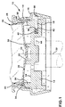
- FIG. 1 shows the chuck for fixing a blood centrifuge bowl to a rotating spindle according to the present invention, generally labeled 10.
- Chuck 10 has four basic components: base plate 12, finger ring 14, collar 16 and plungers 18.
- the centrifugal blood bowl contains the blood to be washed and separated into its components (FIG. 11).
- Blood bowl 20 is hollow and may be generally conical in shape.
- An example of blood bowl 20 is the blood bowl sold in the Sequestra 1000 system sold by Medtronic-Electromedics in Parker, Colorado.
- Blood bowl 20 preferably has a pilot 22 located on the central axis 24 of blood bowl 20. Pilot 22 extends away from the lower base 26 of blood bowl 20.
- Blood bowl 20 has an outer surface 28 and an outer edge 30 that is the outer-most edge of blood bowl 20.
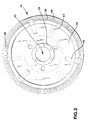
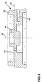
- Chuck 10 includes a generally disk shaped base plate 12 as shown in more detail in FIGS. 3 and 4.
- Base plate 12 has an upper surface 34 and preferably has a cylindrical pilot bore 36 that extends from upper surface 34 of base plate 12. Pilot bore 36 is concentric with central axis 32 of base plate 12. Pilot bore 36 has an inner diameter slightly larger than the outer diameter of pilot 22. In this way, pilot bore 36 may receive pilot 22 when the central axis 24 of blood bowl 20 is aligned with central axis 32 of base plate 12 and blood bowl 20 is moved towards base plate 12.
- An annular ridge 38 extends upward from upper surface 34 around the outer periphery of base plate 12.
- the outer, upper corner of ridge 38 has a flat cam surface 40 formed at an angle to ridge 38.
- Base plate 12 has a series of plunger bores 42 formed in base plate 12 that extend radially from central axis 32. Preferably there are at least three plunger bores 42 to provide a balanced base plate 12 during centrifugation. However, it is to be understood that there may be more or fewer than three plunger bores 42. In the most preferred embodiment, there are six plunger bores 42.
- plunger bores 42 extend within base plate 12 at an angle of about 10 downward from the transverse axis 44 to central axis 32.
- plunger bores 42 extend through base plate 12 essentially parallel to transverse axis 44.
- plunger bores 42 at other angles, including angles upward from the transverse axis 44 are also within the scope of the invention.
- plunger bores 42 are not limited to being precisely aligned with radials from central axis 32.
- Each plunger bore 42 preferably has a spring 46 located at the end of plunger bore 42 closest to central axis 32. Spring 46 biases plunger 18 within plunger bore 42 as will be described in detail hereafter.
- spring 46 performs the biasing function on plunger 18.
- the axes of compression of springs 46 and the corresponding axes of plunger bores 42 are aligned.
- springs 46 for biasing plunger 18 include but are not limited to magnetic repulsion, pneumatic pressure, hydraulic pressure, or, particularly in the embodiment of plunger bores 42 angled downward from the transverse axis 44 to central axis 32, gravitational force.
- Base plate 12 also preferably has a series of lock actuator pin receiving slots 48 formed in ridge 38.
- Lock actuator pin receiving slots 48 extend downwardly into ridge 38 to receive lock actuator pins 50 as will be described in detail hereafter.
- Lock actuator pin receiving slots 48 extend downward into ridge 38 a sufficient distance to allow lock actuator pin 50 to move downward sufficiently to allow blood bowl 20 to be securely positioned against base plate 12.
- Base plate 12 may be made of general plastics or ferrous or non-ferrous alloys including, but not limited to acetal, phenolics, polymide-imides, ABS, aluminum, titanium or tool steels by machining or molding as will be appreciated by those skilled in the art. However, it is to be understood that base plate 12 may also be made of any rigid, durable material.
- Chuck 10 includes a finger ring 14 as shown in more detail in FIGS. 6-8.
- Finger ring 14 has an annular base 52 with a series of fingers 54 extending upward from base 52.
- Base 52 connects fingers 54 and provides a means for positioning fingers 54 by contacting ridge 38 as will be explained hereafter.
- there are 18 fingers 54 although there may be more or fewer fingers 54 as desired.
- finger ring 14 shown in FIG. 8 shows a single finger 54 in cross-section.
- Finger 54 has a collar contact surface 56, a bowl contact surface 58, a cam contact surface 60 and a living hinge 62.
- Living hinge 62 connects finger 54 to annular base 52 and allows finger 54 to pivot around living hinge 62 relative to base 52.
- Fingers 54 are offset inwardly from base 52 at living hinge 62.
- a space 64 separates each finger 54 from its neighboring finger 54 around annular base 52. This allows fingers 54 to flex inwardly around each finger 54's respective living hinge 62 without contacting and interfering with adjoining fingers 54.
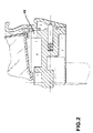
- Finger ring 14 is placed around ridge 38 as shown in FIGS. 1 and 2 so living hinges 62 allow fingers 54 to pivot toward and away from central axis 32 over ridge 38.
- base 52 is positioned around the periphery of ridge 38. Fingers 54 are prevented from moving too far inward over ridge 38 by contact between cam contact surface 60 and cam surface 40.
- Finger ring 14 is preferably made in one piece of a flexible polymeric material such as polyethylene, polypropylene, polyvinyl, acetyl or nylon. However, finger ring 14 may be made of any flexible, durable material. In addition, finger ring 14 may be made in several pieces and joined together as will be clear to those skilled in the art.
- a flexible polymeric material such as polyethylene, polypropylene, polyvinyl, acetyl or nylon.
- finger ring 14 may be made of any flexible, durable material.
- finger ring 14 may be made in several pieces and joined together as will be clear to those skilled in the art.
- a collar 16 is provided as shown in FIGS. 9 and 10.
- Collar 16 has a generally cylindrical main body 66 contoured to fit concentrically around finger ring 14 when finger ring 14 is in position around ridge 38 as described above.
- An annular finger contact surface 68 extends upwardly and inwardly from main body 66. Finger contact surface 68 is shaped to contact collar contact surface 56. The upper end of finger contact surface 68 terminates in a generally upwardly directed upper collar surface 70.
- a plunger capture wall 72 is formed attached to and beneath main body 66 of collar 16. Generally, plunger capture wall 72 is formed a greater radial distance from central axis 32 than main body 66 to form a plunger capture space 74 defined by plunger capture wall 72. Plunger capture wall 72 has a substantially vertical upper wall 76 at a first distance from the central axis 32. Plunger capture wall 72 also has a substantially vertical lower wall 78 at a second distance from central axis 32. The second distance is less than the first distance. A build-up of material at the upper end of lower wall 78 forms an inwardly directed plunger resistance ridge 80.
- a sloping pressure wall 82 connects resistance ridge 80 to upper wall 76.
- Pressure wall 82 has an increasing inner diameter moving upward from resistance ridge 80 to upper wall 76.
- a plunger detent 84 connects resistance ridge 80 to lower wall 78.
- Plunger detent 84 is formed conformal to the outer end 86 of plunger 18. Plunger detent 84 conformally receives the outer end 86 of plunger 18 as will be explained hereafter.
- a lock actuator pin 50 extends inwardly from the main body 66 of collar 16.
- Lock actuator pin 50 has a length that allows lock actuator pin 50 to extend into and interact with lock actuator pin receiving slots 48 in base plate 12 when chuck 10 is assembled as will be explained hereafter.
- Collar 16 is preferably made of ferrous or non-ferrous alloys including, but not limited to, aluminum, titanium or tools steels by machining or other manufacturing means known to those skilled in the art. However, it is to be understood that collar 16 may also be made of any rigid, durable material.
- Collar 16 has been described as being generally cylindrical. This means that collar 16 has a generally tube shape with an inside and an outside surface. Collar 16 may also have a shape other than cylindrical including, but not limited to, conical so long as collar 16 has an inner surface and an outer surface as described herein. The inner surface of collar 16, in whatever shape collar 16 may be, should be configured to have a finger contact surface 68 and may also have a sloping pressure wall 82.
- a plunger 18 is placed in each of the plunger bores 42.
- Plunger 18 preferably has a cylindrical shape of slightly less outer diameter than the inner diameter of plunger bores 42.
- Plunger 18 has an inner end 90 and an outer end 86.
- Plungers 18 are also preferably made of a material having a relatively high density such as bronze, brass, copper, titanium tool steel, iron or babbit alloys, to name but a few possible choices.
- plunger 18 When in place within plunger bores 42, the inner end 90 of plunger 18 contacts spring 46.
- Spring 46 biases the outer end 86 of plunger 18 outwardly from central axis 32.
- Plunger 18 has a length that allows outer end 86 to extend a small distance out of plunger bore 42 when plunger 18 is in plunger bore 42 and inner end 90 is in contact with spring 46.
- FIGS 1 and 2 show the fully assembled chuck 10 in a locked and unlocked configuration, respectively.
- plungers 18 are placed in plunger bores 42 so that the inner ends 90 contact springs 46 and outer ends 86 extend a small distance out of plunger bores 42.
- Finger ring 14 is placed around base plate 12 so that base 52 encircles ridge 38.
- Base 52 is positioned along ridge 38 so that living hinge 62 allows cam contact surface 60 to pivot into and out of contact with cam surface 40.
- Collar 16 is placed concentrically around both base plate 12 and finger ring 14 so that plungers 18 extend into plunger capture space 74.
- a blood bowl 20 can be moved downward into the chuck 10. Blood bowl 20 moves downwardly until pilot 22 locates itself in pilot bore 36. This is accomplished by aligning central axes 24 and 36 and moving blood bowl 20 downward into contact with base plate 12. As a result, blood bowl 20 contacts base plate 12 with central axis 24 and central axis 32 aligned and with pilot 22 engaged with pilot bore 36. As blood bowl 20 moves downwardly, the outer edge 30 of blood bowl 20 contacts lock actuator pin 50. The contact of the outer edge 30 with lock actuator pin 50 moves the entire collar 16 downward with the downward movement of blood bowl 20.
- finger contact surface 68 moves into contact with collar contact surface 56.
- Finger contact surface 68 has a decreasing inner diameter moving upward along finger contact surface 68.
- downward movement of finger contact surface 68 causes inward and downward pressure on collar contact surface 56.
- This inward and downward pressure on collar contact surface 56 causes finger 54 to pivot around living hinge 62.
- This inward and downward motion of finger 54 around living hinge 62 causes bowl contact surface 58 to move into contact with the outer surface 28 of blood bowl 20.
- chuck 10 is connected to a source of rotation so that chuck 10 rotates around central axis 32 at high speed, typically around about 5600 RPM.
- a typical outer diameter of chuck 10 of about 15 cm (six inches) produces centrifugal forces on the outer surface of the chuck 10 in excess of 1400 times the force of gravity.
- This centrifugal force applies as well to plungers 18 within plunger bores 42.
- the centrifugal force applies an outwardly directed force on plungers 18 within bores 42.
- This outward force on plungers 18 causes outer ends 86 to be biased against sloping pressure wall 82.
- plungers 18 receive more centrifugal force, more outward force is applied against sloping pressure wall 82 by contact with outer end 86.
- Sloping pressure wall 82 slopes outwardly moving in an upward direction. As a result, increased outwardly directed pressure on outer end 86 against sloping pressure wall 82 causes sloping pressure wall 82 to be biased to move downwardly. As sloping pressure wall 82 tries to move downwardly, the entire collar 16 tries to move downwardly. As collar 16 tries to move downwardly, finger contact surface 68 tries to move downwardly. This downward pressure on finger contact surface 68 increases the pressure exerted against collar contact surface 56. The increased pressure against collar contact surface 56 creates greater inward and downward pressure by bowl contact surface 58 against the outer surface 28 of blood bowl 20. This increased inward and downward pressure by blood bowl contact surface 58 on the outer surface 28 of blood bowl 20 holds bowl 20 firmly in position within chuck 10.
- downward pressure applied by collar 16, either by manual pressure or by the action of plungers 18, is transferred through fingers 54 into inward and downward pressure on the outer surface 28 of blood bowl 20.
- downward manual movement of blood bowl 20 is transferred to collar 16 to cause downward movement and pressure on collar 16 through lock actuator pins 50.
- lock actuator pins 50 an alternative embodiment of the invention does not include lock actuator pins 50.
- blood bowl 20 is moved into contact with base plate 12 so that pilot 22 locates itself in pilot bore 36. Because there is no lock actuator pin 50, downward movement of blood bowl 20 does not cause downward movement of collar 16. Instead, once pilot 22 is secured in pilot bore 36, manual downward pressure is applied to the upper collar surface 70. This moves collar 16 down so that finger contact surface 68 moves into contact with collar contact surface 56 and the outer end 86 of plunger 18 moves over resistance ridge 62 into contact with the sloped pressure wall 82 of upper wall 76.
- the preferred embodiment of the invention includes the combination of a first part that converts downward movement of an outer collar of a chuck into inward and downward pressure against a blood bowl to be secured in the chuck and a second part that converts centrifugal forces present in a rotating chuck into downward pressure on the collar.
- the first part includes chuck 10 having collar 16 with finger contact surface 68, fingers 54 with collar contact surface 56 and base plate 12.
- the second part includes chuck 10 having base plate 12 with plunger bores 42, collar 16 with sloping pressure wall 82 and plungers 18.
- centrifugal blood bowl 20 Blood bowl 20 has been described as having a pilot 22 located on the central axis 24 of blood bowl 20 that extends away from the lower base 26 of blood bowl 20. Blood bowl 20 moves downwardly until pilot 22 locates itself in pilot bore 36.
- pilot 22 locates itself in pilot bore 36.
- the preferred embodiment contemplates using a base plate 12 with a pilot bore 36, the invention in its broadest form does not require a blood bowl 20 with a pilot 22 or a base plate 12 with a pilot bore 36. Instead, the invention requires that blood bowl 20 be securely in contact with base plate 12 in any configuration that will be clear to those skilled in the art.
- the invention has been described in connection with a specific embodiment.
- the specific embodiment includes a collar 16 having both a finger contact surface 68 and a sloping pressure wall 82.
Landscapes
- Centrifugal Separators (AREA)
- External Artificial Organs (AREA)
Description
whereby, contact between the mass and the sloping surface causes the collar to move downwardly; and
whereby, contact between the second inwardly directed sloping surface and the sloping surface contact point moves the object contact point toward the second axis.
Claims (13)
- A chuck (10)for fixing a blood centrifuge bowl (12) to a rotating spindle, the chuck having a central axis, the chuck comprising:whereby, downward movement of the collar (16) causes the finger contact surface (68) to contact the collar contact surface (56) and move the finger (54) toward the central axis of the chuck (10).a) a base (12) having an outer periphery, andb) a collar (16) having a main body (66), the collar having an upper side and a lower side, characterised in that the base has at least one finger extending upward from the outer periphery of the base, the finger having a collar contact surface (56) and a bowl contact surface (58)and wherein the finger is made of a material with sufficient flexibility to allow the finger to move toward and away from the central axis of the chuck; and in that the main body of the collar is contoured to fit around the base (12) and finger (54), the main body including a finger contact surface (68) that slopes inwardly from the main body moving from the lower side to the upper side, the finger contact surface (68) shaped to contact the collar contact surface (56);
- The chuck of claim 1 wherein the finger (54) has a cam contact surface (60) and the base has an upwardly directed cam surface (40) whereby the fingers are prevented from moving too far toward the central axis of the chuck by contact between the cam contact surface and the cam surface.
- The chuck of claim 2 wherein the base also has at least one lock actuator pin receiving slot (48) formed downwardly in the cam surface (40) and further comprising a lock actuator pin (50) that extends inwardly from the main body (66) of the collar whereby the lock actuator pin (50) is received in the lock actuator pin receiving slot (48).
- The chuck of any preceding claim further comprising an annular finger ring (14) and wherein the at least one finger (54) is attached to and extends away from the finger ring by a flexible connection (62).
- The chuck of claim 4 wherein the flexible connection is a living hinge (62).
- The chuck of any preceding claim wherein the base has at least one plunger bore (42) formed in the base extending radially from the central axis of the chuck.
- The chuck of claim 6 wherein the at least one plunger bore (42) extends within the base at an angle downward from the transverse plane.
- The chuck of claim 6 wherein the at least one plunger bore (42) extends within the base essentially parallel to the transverse plane.
- The chuck of claim 6 wherein the at least one plunger bore (42) extends within the base at an angle upward from the transverse plane.
- The chuck of claim 6 wherein the at least one plunger bore (42) has means (46) for biasing a plunger (18) away from the central axis.
- The chuck of claim 10 wherein the means for biasing is a spring (46).
- The chuck of claim 10 wherein the means for biasing is chosen from the group consisting of magnetic repulsion, pneumatic pressure, hydraulic pressure or gravitational force.
- A method of converting outwardly directed centrifugal forces into inward movement of a finger comprising the steps of :whereby, centrifugal forces acting on the mass cause the mass to move away from the first axis into contact with the first inwardly directed sloping surface;a) providing a mass (18) capable of moving away from a first central axis under the influence of centrifugal forces;b) providing a collar (16) around the mass, the collar having a top and a bottom, a first inwardly directed sloping surface, moving from top to bottom, and a second inwardly directed sloping surface, moving from bottom to top, the collar having a second central axis, the first and second central axes aligned when the collar is in position around the mass; characterised byc) providing at least one finger (54), the finger rotatable around a pivot point (62), the finger having a sloping surface contact point and an object contact point, the sloping surface contact point contacting the second inwardly directed sloping surface, the object contact point being directed toward the second central axis, the finger rotating around the pivot point in response to contact between the second inwardly directed sloping surface and the sloping surface contact point so that the object contact point moves toward the second axis;d) positioning the collar (16) so that the mass (20) contacts the sloping surface when the mass is acted on by centrifugal forces;e) rotating the mass and collar around their aligned first and second central axes;
whereby, contact between the mass and the sloping surface causes the collar to move downwardly; and,
whereby, contact between the second inwardly directed sloping surface and the sloping surface contact point moves the object contact point toward the second axis.
Priority Applications (1)
| Application Number | Priority Date | Filing Date | Title |
|---|---|---|---|
| EP02014154A EP1252933A1 (en) | 1997-03-19 | 1998-03-18 | Method for fixing a blood centrifuge bowl to a rotating spindle |
Applications Claiming Priority (3)
| Application Number | Priority Date | Filing Date | Title |
|---|---|---|---|
| US820201 | 1997-03-19 | ||
| US08/820,201 US5964690A (en) | 1997-03-19 | 1997-03-19 | Mechanism for fixing a blood centrifuge bowl to a rotating spindle |
| PCT/US1998/005345 WO1998041330A1 (en) | 1997-03-19 | 1998-03-18 | Mechanism for fixing a blood centrifuge bowl to a rotating spindle |
Related Child Applications (1)
| Application Number | Title | Priority Date | Filing Date |
|---|---|---|---|
| EP02014154A Division EP1252933A1 (en) | 1997-03-19 | 1998-03-18 | Method for fixing a blood centrifuge bowl to a rotating spindle |
Publications (2)
| Publication Number | Publication Date |
|---|---|
| EP1009538A1 EP1009538A1 (en) | 2000-06-21 |
| EP1009538B1 true EP1009538B1 (en) | 2002-12-04 |
Family
ID=25230169
Family Applications (2)
| Application Number | Title | Priority Date | Filing Date |
|---|---|---|---|
| EP02014154A Withdrawn EP1252933A1 (en) | 1997-03-19 | 1998-03-18 | Method for fixing a blood centrifuge bowl to a rotating spindle |
| EP98912962A Expired - Lifetime EP1009538B1 (en) | 1997-03-19 | 1998-03-18 | Mechanism for fixing a blood centrifuge bowl to a rotating spindle |
Family Applications Before (1)
| Application Number | Title | Priority Date | Filing Date |
|---|---|---|---|
| EP02014154A Withdrawn EP1252933A1 (en) | 1997-03-19 | 1998-03-18 | Method for fixing a blood centrifuge bowl to a rotating spindle |
Country Status (5)
| Country | Link |
|---|---|
| US (1) | US5964690A (en) |
| EP (2) | EP1252933A1 (en) |
| JP (1) | JP4187273B2 (en) |
| DE (1) | DE69809936T2 (en) |
| WO (1) | WO1998041330A1 (en) |
Families Citing this family (19)
| Publication number | Priority date | Publication date | Assignee | Title |
|---|---|---|---|---|
| US6315707B1 (en) | 1999-09-03 | 2001-11-13 | Baxter International Inc. | Systems and methods for seperating blood in a rotating field |
| US6860846B2 (en) * | 1999-09-03 | 2005-03-01 | Baxter International Inc. | Blood processing systems and methods with umbilicus-driven blood processing chambers |
| US6322488B1 (en) | 1999-09-03 | 2001-11-27 | Baxter International Inc. | Blood separation chamber with preformed blood flow passages and centralized connection to external tubing |
| US6524231B1 (en) | 1999-09-03 | 2003-02-25 | Baxter International Inc. | Blood separation chamber with constricted interior channel and recessed passage |
| US20020077241A1 (en) * | 1999-09-03 | 2002-06-20 | Baxter International Inc. | Blood processing systems and methods with quick attachment of a blood separation chamber to a centrifuge rotor |
| US6463335B1 (en) | 1999-10-04 | 2002-10-08 | Medtronic, Inc. | Temporary medical electrical lead having electrode mounting pad with biodegradable adhesive |
| US6849039B2 (en) * | 2002-10-24 | 2005-02-01 | Baxter International Inc. | Blood processing systems and methods for collecting plasma free or essentially free of cellular blood components |
| US7297272B2 (en) | 2002-10-24 | 2007-11-20 | Fenwal, Inc. | Separation apparatus and method |
| US7998052B2 (en) * | 2006-03-07 | 2011-08-16 | Jacques Chammas | Rotor defining a fluid separation chamber of varying volume |
| US8506825B2 (en) * | 2006-11-27 | 2013-08-13 | Sorin Group Italia S.R.L. | Method and apparatus for controlling the flow rate of washing solution during the washing step in a blood centrifugation bowl |
| EP2127578A1 (en) * | 2008-05-30 | 2009-12-02 | Koninklijke Philips Electronics N.V. | Kitchen appliance |
| EP2138237B1 (en) * | 2008-06-10 | 2011-01-19 | Sorin Group Italia S.r.l. | A securing mechanism, particularly for blood separation centrifuges and the like |
| PT2592977T (en) | 2010-07-16 | 2022-03-14 | Nestle Sa | Device for preparing a beverage by centrifugation |
| CN101915653B (en) * | 2010-08-02 | 2011-12-28 | 浙江大学 | Centrifuge used in multi-parameter complex test environment |
| CN101913437B (en) * | 2010-08-02 | 2012-11-07 | 浙江大学 | Multi-parameter compound environmental tester |
| EP2694217B1 (en) | 2011-04-08 | 2018-07-18 | Sorin Group Italia S.r.l. | Disposable device for centrifugal blood separation |
| US10039876B2 (en) | 2014-04-30 | 2018-08-07 | Sorin Group Italia S.R.L. | System for removing undesirable elements from blood using a first wash step and a second wash step |
| TWI645925B (en) * | 2017-01-19 | 2019-01-01 | 貝斯特精密機械有限公司 | Front-mounted hydraulic chuck |
| CN108773504B (en) * | 2018-04-17 | 2020-05-05 | 北京航空航天大学 | A motion simulator that can work in an ultra-low temperature and high vacuum environment |
Family Cites Families (18)
| Publication number | Priority date | Publication date | Assignee | Title |
|---|---|---|---|---|
| US1385306A (en) * | 1918-04-08 | 1921-07-19 | Courtaulds Ltd | Spinning-box for artificial silk |
| US2536793A (en) * | 1945-03-02 | 1951-01-02 | Separator Ab | Sealing device for centrifugal separators |
| US3317127A (en) * | 1945-03-02 | 1967-05-02 | Little Inc A | Centrifuge |
| US4684361A (en) * | 1985-10-11 | 1987-08-04 | Cardiovascular Systems, Inc. | Centrifuge |
| US3706412A (en) * | 1971-07-28 | 1972-12-19 | Haemonetics Corp | Pressure-actuated centrifuge chuck and centrifuge incorporating the same |
| US3785549A (en) * | 1972-07-31 | 1974-01-15 | Haemonetics Corp | Centrifuge chuck for disposable, snap-in centrifuge rotor |
| SU1150038A1 (en) * | 1983-12-21 | 1985-04-15 | Специальное Конструкторское Бюро Биофизической Аппаратуры | Centrifuge for separating blood |
| US4692136A (en) * | 1985-10-11 | 1987-09-08 | Cardiovascular Systems Inc. | Centrifuge |
| US4795419A (en) * | 1985-10-11 | 1989-01-03 | Kardiothor, Inc. | Centrifuge |
| US4718888A (en) * | 1986-03-10 | 1988-01-12 | Cardiovascular Systems, Inc. | Centrifuge bowl mount |
| IT1202514B (en) * | 1987-02-10 | 1989-02-09 | Dideco Spa | SPINDLE FOR FASTENING OF CELL FOR CENTRIFUGATION OF BLOOD, AND SIMILAR |
| US4767396A (en) * | 1987-03-03 | 1988-08-30 | Haemonetics Corporation | Method and apparatus for processing biological fluids |
| US4900298A (en) * | 1987-08-21 | 1990-02-13 | Cobe Laboratories, Inc. | Centrifuge drive and support assembly |
| IT1230356B (en) * | 1989-07-14 | 1991-10-18 | Dideco Spa | BLOCK SPINDLE BLOCKING DEVICE FOR BLOOD CENTRIFUGATION. |
| WO1991014493A1 (en) * | 1990-03-28 | 1991-10-03 | Micro Diagnostics Corporation | Miniature centrifuge with locking hub |
| EP0572656B1 (en) * | 1991-12-23 | 1997-11-05 | Baxter International Inc. | Centrifuge with separable bowl and spool elements providing access to the separation chamber |
| US5591113A (en) * | 1994-10-31 | 1997-01-07 | Cobe Laboratories, Inc. | Centrifugally assisted centrifuge bowl mount |
| US5658231A (en) * | 1995-09-21 | 1997-08-19 | Haemonetics Corporation | Mechanism for securing a separation bowl to a mechanical chuck |
-
1997
- 1997-03-19 US US08/820,201 patent/US5964690A/en not_active Expired - Lifetime
-
1998
- 1998-03-18 DE DE69809936T patent/DE69809936T2/en not_active Expired - Fee Related
- 1998-03-18 EP EP02014154A patent/EP1252933A1/en not_active Withdrawn
- 1998-03-18 EP EP98912962A patent/EP1009538B1/en not_active Expired - Lifetime
- 1998-03-18 WO PCT/US1998/005345 patent/WO1998041330A1/en not_active Ceased
- 1998-03-18 JP JP54077398A patent/JP4187273B2/en not_active Expired - Lifetime
Also Published As
| Publication number | Publication date |
|---|---|
| EP1009538A1 (en) | 2000-06-21 |
| JP2001517144A (en) | 2001-10-02 |
| US5964690A (en) | 1999-10-12 |
| WO1998041330A1 (en) | 1998-09-24 |
| JP4187273B2 (en) | 2008-11-26 |
| DE69809936D1 (en) | 2003-01-16 |
| DE69809936T2 (en) | 2003-09-04 |
| EP1252933A1 (en) | 2002-10-30 |
Similar Documents
| Publication | Publication Date | Title |
|---|---|---|
| US5964690A (en) | Mechanism for fixing a blood centrifuge bowl to a rotating spindle | |
| EP1721586B1 (en) | Cap and activation tool | |
| US5816583A (en) | Integral locking sleeve chuck | |
| KR100259551B1 (en) | Tool unit clamping apparatus having a locking mechanism with increased gripping force | |
| WO1991016015A1 (en) | Acetabular cup assembly | |
| CA2202251C (en) | Acetabular cup-liner assembly | |
| JPH11510744A (en) | Chuck | |
| CA2178957A1 (en) | Removable nosepieces for chucks and similar tool holders | |
| CN105289858A (en) | Drive Head, Kit Comprising The Drive Head, And Centrifuge | |
| EP0956174A1 (en) | Chuck with gripping mechanism stop | |
| EP0111492A1 (en) | Centrifuge/rotor attachment assembly | |
| US8485957B2 (en) | Securing mechanism, particularly for blood separation centrifuges and the like | |
| JP4278295B2 (en) | Tool coupling system for machine tools | |
| US4398886A (en) | Rotatable socket for a dental handpiece | |
| JP7766470B2 (en) | Dental disc blank retention ring | |
| CN1185764A (en) | Counter centrifugel chuck and mounting system | |
| CA2021065A1 (en) | Device for locking a blood centrifugation cell on a chuck | |
| CN1227088C (en) | Cutter tool holder for drilling machine and/or impact machine tool | |
| DK174383B1 (en) | Link to ostomy bag | |
| US7381018B2 (en) | Tool chuck | |
| US6502836B1 (en) | Chuck with spring leg dust cover | |
| WO1988008348A1 (en) | Four-jawed self-centering chuck | |
| GB2214999A (en) | Balance weight for rotating body | |
| WO2003053589A2 (en) | Rotary centrifuge having pivoting buckets for holding samples | |
| JPH10503717A (en) | Tapping collet |
Legal Events
| Date | Code | Title | Description |
|---|---|---|---|
| PUAI | Public reference made under article 153(3) epc to a published international application that has entered the european phase |
Free format text: ORIGINAL CODE: 0009012 |
|
| 17P | Request for examination filed |
Effective date: 19991019 |
|
| AK | Designated contracting states |
Kind code of ref document: A1 Designated state(s): DE IT |
|
| 17Q | First examination report despatched |
Effective date: 20010531 |
|
| GRAG | Despatch of communication of intention to grant |
Free format text: ORIGINAL CODE: EPIDOS AGRA |
|
| GRAG | Despatch of communication of intention to grant |
Free format text: ORIGINAL CODE: EPIDOS AGRA |
|
| GRAH | Despatch of communication of intention to grant a patent |
Free format text: ORIGINAL CODE: EPIDOS IGRA |
|
| GRAH | Despatch of communication of intention to grant a patent |
Free format text: ORIGINAL CODE: EPIDOS IGRA |
|
| GRAA | (expected) grant |
Free format text: ORIGINAL CODE: 0009210 |
|
| AK | Designated contracting states |
Kind code of ref document: B1 Designated state(s): DE IT |
|
| PG25 | Lapsed in a contracting state [announced via postgrant information from national office to epo] |
Ref country code: IT Free format text: LAPSE BECAUSE OF FAILURE TO SUBMIT A TRANSLATION OF THE DESCRIPTION OR TO PAY THE FEE WITHIN THE PRESCRIBED TIME-LIMIT;WARNING: LAPSES OF ITALIAN PATENTS WITH EFFECTIVE DATE BEFORE 2007 MAY HAVE OCCURRED AT ANY TIME BEFORE 2007. THE CORRECT EFFECTIVE DATE MAY BE DIFFERENT FROM THE ONE RECORDED. Effective date: 20021204 |
|
| REF | Corresponds to: |
Ref document number: 69809936 Country of ref document: DE Date of ref document: 20030116 |
|
| PLBE | No opposition filed within time limit |
Free format text: ORIGINAL CODE: 0009261 |
|
| STAA | Information on the status of an ep patent application or granted ep patent |
Free format text: STATUS: NO OPPOSITION FILED WITHIN TIME LIMIT |
|
| 26N | No opposition filed |
Effective date: 20030905 |
|
| PGFP | Annual fee paid to national office [announced via postgrant information from national office to epo] |
Ref country code: DE Payment date: 20050331 Year of fee payment: 8 |
|
| PG25 | Lapsed in a contracting state [announced via postgrant information from national office to epo] |
Ref country code: DE Free format text: LAPSE BECAUSE OF NON-PAYMENT OF DUE FEES Effective date: 20061003 |