EP1008729A2 - Actionneur hydraulique à ailettes - Google Patents
Actionneur hydraulique à ailettes Download PDFInfo
- Publication number
- EP1008729A2 EP1008729A2 EP99122062A EP99122062A EP1008729A2 EP 1008729 A2 EP1008729 A2 EP 1008729A2 EP 99122062 A EP99122062 A EP 99122062A EP 99122062 A EP99122062 A EP 99122062A EP 1008729 A2 EP1008729 A2 EP 1008729A2
- Authority
- EP
- European Patent Office
- Prior art keywords
- rotor
- locking means
- case
- retaining
- engaging
- Prior art date
- Legal status (The legal status is an assumption and is not a legal conclusion. Google has not performed a legal analysis and makes no representation as to the accuracy of the status listed.)
- Granted
Links
Images


Classifications
-
- F—MECHANICAL ENGINEERING; LIGHTING; HEATING; WEAPONS; BLASTING
- F01—MACHINES OR ENGINES IN GENERAL; ENGINE PLANTS IN GENERAL; STEAM ENGINES
- F01L—CYCLICALLY OPERATING VALVES FOR MACHINES OR ENGINES
- F01L1/00—Valve-gear or valve arrangements, e.g. lift-valve gear
- F01L1/34—Valve-gear or valve arrangements, e.g. lift-valve gear characterised by the provision of means for changing the timing of the valves without changing the duration of opening and without affecting the magnitude of the valve lift
- F01L1/344—Valve-gear or valve arrangements, e.g. lift-valve gear characterised by the provision of means for changing the timing of the valves without changing the duration of opening and without affecting the magnitude of the valve lift changing the angular relationship between crankshaft and camshaft, e.g. using helicoidal gear
- F01L1/3442—Valve-gear or valve arrangements, e.g. lift-valve gear characterised by the provision of means for changing the timing of the valves without changing the duration of opening and without affecting the magnitude of the valve lift changing the angular relationship between crankshaft and camshaft, e.g. using helicoidal gear using hydraulic chambers with variable volume to transmit the rotating force
- F01L2001/34423—Details relating to the hydraulic feeding circuit
- F01L2001/34436—Features or method for avoiding malfunction due to foreign matters in oil
- F01L2001/3444—Oil filters
-
- F—MECHANICAL ENGINEERING; LIGHTING; HEATING; WEAPONS; BLASTING
- F01—MACHINES OR ENGINES IN GENERAL; ENGINE PLANTS IN GENERAL; STEAM ENGINES
- F01L—CYCLICALLY OPERATING VALVES FOR MACHINES OR ENGINES
- F01L1/00—Valve-gear or valve arrangements, e.g. lift-valve gear
- F01L1/34—Valve-gear or valve arrangements, e.g. lift-valve gear characterised by the provision of means for changing the timing of the valves without changing the duration of opening and without affecting the magnitude of the valve lift
- F01L1/344—Valve-gear or valve arrangements, e.g. lift-valve gear characterised by the provision of means for changing the timing of the valves without changing the duration of opening and without affecting the magnitude of the valve lift changing the angular relationship between crankshaft and camshaft, e.g. using helicoidal gear
- F01L1/3442—Valve-gear or valve arrangements, e.g. lift-valve gear characterised by the provision of means for changing the timing of the valves without changing the duration of opening and without affecting the magnitude of the valve lift changing the angular relationship between crankshaft and camshaft, e.g. using helicoidal gear using hydraulic chambers with variable volume to transmit the rotating force
- F01L2001/3445—Details relating to the hydraulic means for changing the angular relationship
- F01L2001/34453—Locking means between driving and driven members
- F01L2001/34469—Lock movement parallel to camshaft axis
-
- F—MECHANICAL ENGINEERING; LIGHTING; HEATING; WEAPONS; BLASTING
- F01—MACHINES OR ENGINES IN GENERAL; ENGINE PLANTS IN GENERAL; STEAM ENGINES
- F01L—CYCLICALLY OPERATING VALVES FOR MACHINES OR ENGINES
- F01L1/00—Valve-gear or valve arrangements, e.g. lift-valve gear
- F01L1/34—Valve-gear or valve arrangements, e.g. lift-valve gear characterised by the provision of means for changing the timing of the valves without changing the duration of opening and without affecting the magnitude of the valve lift
- F01L1/344—Valve-gear or valve arrangements, e.g. lift-valve gear characterised by the provision of means for changing the timing of the valves without changing the duration of opening and without affecting the magnitude of the valve lift changing the angular relationship between crankshaft and camshaft, e.g. using helicoidal gear
- F01L1/3442—Valve-gear or valve arrangements, e.g. lift-valve gear characterised by the provision of means for changing the timing of the valves without changing the duration of opening and without affecting the magnitude of the valve lift changing the angular relationship between crankshaft and camshaft, e.g. using helicoidal gear using hydraulic chambers with variable volume to transmit the rotating force
- F01L2001/3445—Details relating to the hydraulic means for changing the angular relationship
- F01L2001/34453—Locking means between driving and driven members
- F01L2001/34473—Lock movement perpendicular to camshaft axis
-
- Y—GENERAL TAGGING OF NEW TECHNOLOGICAL DEVELOPMENTS; GENERAL TAGGING OF CROSS-SECTIONAL TECHNOLOGIES SPANNING OVER SEVERAL SECTIONS OF THE IPC; TECHNICAL SUBJECTS COVERED BY FORMER USPC CROSS-REFERENCE ART COLLECTIONS [XRACs] AND DIGESTS
- Y10—TECHNICAL SUBJECTS COVERED BY FORMER USPC
- Y10T—TECHNICAL SUBJECTS COVERED BY FORMER US CLASSIFICATION
- Y10T74/00—Machine element or mechanism
- Y10T74/21—Elements
- Y10T74/2101—Cams
- Y10T74/2102—Adjustable
Definitions
- the present invention relates to a vane type hydraulic actuator for controlling the timing of opening and closing of an intake and/or exhaust valve, corresponding to an operational state of an engine.
- Fig.18 is a cross sectional view of a vane type hydraulic actuator invented by the inventors of this application and is disclosed in JP-9-314069-A.
- Fig.19 is a detailed cross sectional view of the plunger part shown in Fig.18.
- Fig.20 is a cross sectional view of the plunger part in a state that a hydraulic pressure is applied.
- Reference numeral 19 denotes an intake side cam shaft having an intake side cam 19a.
- An actuator 40 is connected to an end of the intake side cam shaft 19, and a timing pulley 21 is disposed around the actuator 40.
- the working oil of the actuator 40 is lubrication oil, delivered from an engine (not shown).
- the actuator is actuated by the working oil so as to adjust phase angle of the rotation of the intake side cam shaft 19 so that the opening and closing timings of intake valves of the engine can be continuously adjusted.
- the intake side cam shaft 41 is supported by a bearing 19.
- the actuator 40 has a housing 42, which can freely rotate around the intake side cam shaft 19.
- a case 43 is fixed to the housing 42. And a vane type rotor 44 is received in the case 43.
- the vane rotor 44 is fixed to the intake side cam shaft 19 by means of bolts 45.
- the rotor 44 is rotatable relative to the case 43 in a predetermined anglular region.
- the case 43 and the rotor 44 form hydraulic pressure chambers separated from each other.
- a chip seal 46 is disposed between the case 43 and the rotor 44 so that no oil leakage between the oil pressure chambers can occur.
- a back spring 47 made of an iron plate is disposed to push the chip seal 46 towards the rotor 44.
- the housing 42, the case 43 and a cover 48 connected to the case 43 are fixed by a common volt 49.
- An O-ring 50 is disposed between the case 43 and the bolt 50.
- a plate 51 is fixed to the cover 48 by a bolt 52.
- Reference numerals 53, 54 denote O-rings.
- a cylindrical holder 55 is disposed in the rotor 44.
- the cylindrical holder 55 has an engaging hole 55a, which can engage with a plunger 56, as will be explained below.
- the plunger 56 disposed in the housing 42 can slide therein and has an engaging shaft 56a, which can engage with the engaging hole 55a of the holder 55.
- the plunger 56 is pushed by a spring 57 towards the holder 55.
- Working oil is delivered into the engaging hole 55a of the holder 55 through a plunger oil channel 58.
- the plunger 56 moves opposingly to the spring 57 so that the plunger 56 is unlocked from the holder 55.
- the rotor 44 is fixed to the intake side cam shaft 19 by means of a bolt 60.
- Reference numerals 59, 61 denote air holes.
- a first and second oil channels 62, 63 are disposed in the intake side cam shaft 19 and the rotor 44.
- the first oil channel 62 communicates with an oil pressure chamber for timing retard 73
- the second oil channel 63 communicates with an oil pressure chamber for timing advance 74.
- the amount of the working oil to be delivered to the actuator 40 is controlled by an oil control valve 80, which will be abbreviated to OCV hereinafter.
- the OCV 80 comprises a valve housing 81, a spool 82 which can slide in the valve housing 81, a spring 83 urging the spool 82 toward one direction, and a linear solenoid 84 for displacing the spool 82 resisting the spring 83.
- the OCV is connected with an oil pan 91 through an oil supplying pipe 85a.
- An oil pump 92 and an oil filter 93 are disposed in the oil supplying pipe 85a.
- the first and second oil channels 62, 63 are connected with the OCV 80 through a first and second oil pipes 89, 90, respectively.
- the working oil returns to the oil pan 91 from the OCV 80 through an oil drain pipe 88.
- the oil pan 91, the oil pump 92, the oil filter 93 are a part of a lubrication system for lubricating portions to be lubricated in the engine (not shown), and simultaneously they form a working oil delivery system to the actuator 40.
- An electronic control unit 100 which is abbreviated to ECU hereinafter, controls the amount of fuel injection into the engine, the timings of the ignition, and the timing of the opening and closing of valves.
- the control corresponds to the inputs from an intake air amount sensor, a throttle sensor, crank angle sensor and a cam angle sensor, which are not shown.
- the electronic control unit 100 further controls the closing timing of valves after the switching off of the ignition switch.
- Fig.21 is a cross sectional view of Fig.18 along the line X-X.
- Fig.22 shows a state in which a slide plate shown in Fig.21 is displaced.
- Fig.23 is a cross sectional view of Fig.18 along the line Y-Y,
- Fig.24 is a cross sectional view of Fig.18 along the line Z-Z.
- a first to fourth vanes 64-67 project radially from the rotor 44.
- a chip seal 68 is disposed at the tip of each vane 64-67.
- the chip seal 68 contacts with the inner surface of the case 43 and can slide along the surface.
- the chip seals 68 seal between the chambers disposed at both sides of the vanes.
- a back spring (not shown) is disposed behind each chip seals 68 for increasing the capacity of the sealing.
- the shoe 43 has a bolt hole 72, into which the bolt 49 shown in Fig.18 is screwed.
- each shoe 71 contacts with a vane supporting portion 69 of the rotor, namely the hub of the rotor, which supports the vanes.
- the tip portion of each shoe 71 slides along the outer surface of the vane supporting portion 69.
- Each room between the adjacent shoes 71 is divided by the corresponding shoe 71 into an oil pressure chamber for timing retard 73 and an oil pressure chamber for timing advance 74.
- These chambers 73, 74 are formed alternatively and have a form of a sector like room contoured peripherally by the inner surface of the case 43 and the outer surface of the rotor 44 and contoured radially by one of the shoes 71 and one of the vanes 64-67 of the rotor 44.
- the oil pressure chamber for timing retard 73 is used for swing the first to fourth vanes 64-67 so that the timing of the opening and closing of valves is retarded.
- the oil chamber for timing advance 74 is used for swing the first to fourth vanes 64-67 so that the timing of the opening and closing of valves is advanced.
- the oil pressure chamber for timing retard 73 and the oil pressure chamber for timing advance 74 disposed at both side of the first vane 64 are communicated through a communicating channel 75, which passes through the first vane 64.
- a groove 76 is disposed in the communicating channel 75, and the plunger oil channel 58 communicates with the groove 76.
- a slide plate 77 is disposed in the groove 76.
- the slide plate 77 divides the communicating channel 75 into two parts in such a manner that the oil leakage between the oil pressure chamber for timing retard 73 and the oil pressure chamber for timing advance 74 is prevented.
- the slide plate 77 moves toward the oil pressure chamber for timing advance 74, when the oil pressure in the oil pressure chamber for timing retard 73 is higher. It moves towards the oil chamber for timing retard 73, when the pressure in the oil pressure chamber for timing advance 74 is higher.
- the arrow marks in Figs. 21, 23, 24 show the rotation direction of the actuator 40 as a whole.
- the oil pressure chambers for timing retard and advance 73, 74 are surrounded by the housing 42, case 43, rotor 44 and cover 48.
- the oil pressure chamber for timing retard 73 communicates with the first oil channel 62 so that working oil is delivered to the chamber 73 through the first oil channel 62.
- the oil pressure chamber for timing advance 74 communicates with the second oil channel 63 so that working oil is delivered to the chamber 74 through the second oil channel 63.
- the rotor 44 rotates relatively to the housing 42, when the volumes of the oil pressure chambers 73, 74 change, corresponding to the amount of working oil delivered to each of the oil pressure chambers 73, 74
- the rotor 44 is positioned, as shown in Fig. 21, at the maximum timing advance position, namely, the rotor 44 has rotated at most in the timing advance direction. Also the oil pump 92 is stopping, therefore, no working oil is delivered either to the first and second oil channels 62, 63, as a result, no working oil is supplied to the plunger oil channel 58. Consequently, the oil pressure in the actuator 40 is low. As a result, the plunger 56 is pushed by the urging force of the spring 57 towards the holder 55 so that the engaging shaft 56a of the plunger 56 engages with the engaging hole 55a of the holder 55, that is to say, the rotor 44 is locked to the housing 42.
- a "timing advance direction” is a rotation direction of the rotor relative to the housing to advance the timing of the opening and closing of the valves
- a “timing retard direction” is a rotation direction of the rotor relative to the housing to retard the timing of the opening and closing of the valves.
- the oil pump 92 functions to increase the oil pressure to the OCV 80 so that working oil is delivered through the first oil pipe 89 and the first oil channel 62 to the oil pressure chamber for timing retard 73 in the actuator 40. Due to the high oil pressure in the oil pressure chamber for timing retard 73, the slide plate 77 moves towards the oil pressure chamber for timing advance 74. As a result, the oil pressure chamber for timing retard 73 communicates with the plunger oil channel 58 so that the working oil is delivered through this plunger oil channel 58 into the engaging hole 55a of the holder 55.
- the plunger 56 is urged toward the spring, resisting the spring force, so that the engaging shaft 56a of the plunger 56 is pushed out from the engaging hole 55a of the holder 55a. That is to say, the engaging or locking between the plunger 56 and the rotor 44 is released.
- each vane 65-67 of the rotor 44 is pressed to a shoe 71 from the oil pressure chamber 73, and contacts with a flank of the shoe 71. Therefore, even in the unlocked state between the plunger 56 and the rotor 44, the housing 42 and the rotor 44 are pressing to each other due to the oil pressure in the oil pressure chamber for timing retard 73. As a result, the vibration or clashing in the actuator can be reduced or eliminated.
- working oil is delivered from the OCV 80 to the oil chamber for timing advance 74 through the second oil pipe 90 and the second oil channel 63.
- the oil pressure in the oil chamber for timing advance 74 is delivered to the communicating channel 75 so that the slide plate 77 is pushed to move towards the oil pressure chamber for timing retard 73.
- the plunger oil channel 58 communicates with the communicating channel 75 at the oil pressure chamber for timing advance 74 side so that the oil pressure in the oil pressure chamber for timing advance 74 is supplied to the plunger oil channel 58. Due to this high oil pressure, the plunger 56 moves towards the housing 42 resisting the force of the spring 57, so that the engaging or locking between the plunger 56 and the holder 55 is released.
- the opening and closing of the OCV 80 is controlled so as to control the oil delivery to the oil pressure chambers for timing retard and advance 73, 74 so that the rotation angle of the rotor 44 relative to the rotation angle of the housing 42 is changed, that is to say, the rotor 44 is rotated in the timing advance direction or in the timing retard direction.
- the rotor 44 is rotated at most in the timing advance direction, the rotor rotates at a state that each vane 64-67 of the rotor 44 is contacting with a shoe 71 from the oil pressure chamber for timing retard 73 side, as shown in Fig.22.
- the oil pressure in the oil pressure chamber for timing retard 73 is higher than that in the oil pressure chamber for timing advance 74, the rotor 44 rotates in the timing retard direction relatively to the housing 42.
- the rotor 44 is controlled to rotate relatively to the housing 42 in the timing advance direction or in the timing retard direction, by adjusting the oil delivery to the oil pressure chambers for timing advance and retard 73, 74.
- the oil leakage at the oil delivery between the oil pressure chambers 73, 74 is prevented by means of chip seals 46, 68.
- the oil pressure provided from the OCV 80 is controlled by the ECU 100, corresponding to the outputs from a position sensor, which detects the rotation angel of the rotor 44 relative to the housing 42, and a crank angle sensor, which determines the pressure to be supplied from the oil pump 92.
- JP-9-60507-A Another apparatus for adjusting the timings of the opening and closing of valves in an internal combustion engine using a vane type hydraulic actuator is disclosed in JP-9-60507-A, which employs a structure that one stopper pin, as a locking means, locks the rotor in the maximum timing retard position or in the maximum timing advance position, while the timings of the opening and closing of valves are adjusted at the starting of the engine.
- vane type actuators in the prior art employ a structure that one plunger 56 or one stopper pin, as a locking means, locks the rotor in the maximum timing retard position or in the maximum timing advance position, while the timings of the opening and closing of valves are adjusted at the starting of the engine.
- the engine shall be started from a state, in which the rotor in the intake side is shifted a little from the maximum timing retard position towards the maximum timing advance position, and the rotor in the exhaust side is shifted a little from the maximum timing advance position towards the maximum timing retard position.
- the rotors in the intake side and the exhaust side have to be locked at an intermediate position.
- the locking at an intermediate position was difficult, when the structures of the vane type hydraulic actuators in the prior art are employed.
- the apparatus will be of more complex, when such structure in the prior art is modified to lock the rotors in an intermediate position. That is to say, the vane type hydraulic actuator in the prior art has the drawback that an optimization of timings of opening and closing of valves using a simplified structure was impossible.
- An object of the present invention is to eliminate the drawback of the vane type hydraulic actuator in the prior art.
- Another object is to propose a vane type hydraulic actuator, in which the rotor can be locked securely at an arbitrary timing retard or timing advance position, when the engine is stopping, so that the timing of opening and closing of valves can be optimized.
- Another object is to propose a vane type hydraulic actuator, in which an unbalanced rotation of the rotor can be prevented.
- Another object is to propose a vane type hydraulic actuator, in which the assembling of the components for locking the rotor is easy.
- Another object is to propose a vane type hydraulic actuator, in which the rotor can be smoothly displaced to an arbitrary position, and the displaced rotor can be securely locked at the position.
- Another object is to propose a vane type hydraulic actuator, in which the relative velocity between the rotor and the case can be rapidly decreased, and simultaneously the allowance of dimensions of the components required in the assembling process can be loosened.
- Another object is to propose a vane type hydraulic actuator, in which the locking of the rotor can be released smoothly, using either of the oil pressure in the oil pressure chambers for timing retard or timing advance.
- Another object is to propose a vane type hydraulic actuator, in which the rotor can be held securely at any position where the locking of the rotor is released.
- Another object is to propose a vane type hydraulic actuator, in which the misassembling of components of the actuator in the production process can be absolutely prevented so that the efficiency of the assembling of components of the actuator can be improved.
- Another object is to propose a vane type hydraulic actuator, in which drawing back of locking elements from a rotor retaining position can be prevented.
- Another object is to propose a vane type hydraulic actuator, in which, when the rotor is offset from a locking position, the offset of rotor can be corrected, and the rotor can be securely locked at the corrected locking position.
- a vane type hydraulic actuator comprising:
- the guide locking means is disposed in a first vane, and the retaining locking means is disposed in a second vane located symmetrically with the first vane in respect with the axis of the rotor.
- the guide locking means and the retaining locking means are disposed in either of a vane of the rotor or a shoe of the case and are arranged to be adjacent to each other in the direction of the axis of the rotor, they are configured to move in the radial direction of the rotor so that the rotor can be locked to the case and can be disengaged from the case.
- the guide locking means has a first engaging boss formed as a tapered pin
- the guide locking means has a first engaging boss formed as a parallel pin; a first engaging recess is disposed in a portion rotating together with the case; and a friction increasing means is disposed in the base region of the first engaging recess so that the first engaging boss can contact with the friction increasing means.
- a lock releasing oil pressure channel for supplying oil pressure to the guide locking means and the retaining locking means so as to release the engagement between the rotor and the case; and an oil channel switching means for connecting the lock releasing oil pressure channel to either of the oil pressure chambers for timing retard or the oil chamber for timing advance.
- a fluid channel is disposed in a portion rotating together with the case so that spaces, which are formed behind each of the guide locking means and the retaining locking means when the rotor is locked to the case, communicate to the atmosphere through the fluid channel, only when the rotor is locked to the case.
- the cross section of the guide locking means is different from that of the retaining locking means.
- each of the guide locking means and the retaining locking means is urged so as to lock the rotor to the case by urging means; and the urging force of the urging means for the guide locking means is designed to be stronger than that of the urging means for the retaining locking means.
- the length in the peripheral direction of the tip portion of the vane having the guide locking means is substantially identical to that of the retaining locking means.
- the vane having the guide locking means and/or the vane having the retaining locking means have a weight balancing hole so as to balance the rotation of the rotor.
- the first engaging recess for receiving the guide locking means is tapered in such a manner that the tapering angle of the first engaging recess is larger than the tapering angle of the first engaging boss.
- the first engaging recess for receiving the first engaging boss of the guide locking means is disposed in a sliding means which is resiliently held in a portion rotating together with the case.
- the locking means for retaining the rotor to the case is a combination of a guide locking means for guiding the rotor to a predetermined locking position and a retaining locking means for retaining the rotor to the rotor, which has been guided to the locking position. Therefore advantages are obtained in that, though the structure is simple, the rotor can be guided to a predetermined locking position using the guide locking means to lock it temporarily, and after temporarily locking, the rotor can be retained securely at an arbitrary position for a desired timing retard or for timing advance, using the retaining locking means, so that the timing of the opening and closing of the valves can be optimized.
- the guide locking means and the retaining locking means are designed to be disposed either in a common vane of the rotor or in a common shoe of the case, and they are arranged so as to be adjacent in the direction of the axis of the rotor, further they can move in the radial direction of the rotor, the efficiency of the production process is improved, because they can be assembled side by side. And the preciseness of the positioning of the rotor can be improved, because the rotor is temporarily locked by the guide locking means, which is found in the adjacent position of the retaining locking means.
- the guide locking means has a first engaging boss formed as a tapered pin
- the retaining locking means has a second engaging pin formed as a parallel pin
- their corresponding engaging recess having a recessed portion corresponding to those first and second engaging boss, are disposed in either of a portion rotating together with the case or the rotor so that they receive the first and second engaging boss
- the tapered first engaging boss of the guide locking means can easily enter the corresponding tapered engaging recess. Therefore the rotor can be smoothly positioned to a predetermined locking position.
- the second engaging boss, formed as a parallel pin, of the retaining locking means is offset from the corresponding engaging recess, the offset can be corrected easily using the guide locking means.
- the second engaging boss of the retaining means enters into the second engaging recess so that the rotor can be retained securely at an arbitrary position for timing retard and the timing advance, therefore the timing of opening and closing of the valves can be optimized.
- the guide locking means has a first engaging boss formed as a parallel pin, and the first engaging recess for receiving loosely the first engaging boss is disposed in a portion rotating together with the case, further a friction increasing member is disposed in the base portion of the first engaging recess so that the first engaging boss can contact with it, the relative velocity between the rotor and the case decreases, due to the increased friction resistance between the first engaging boss and the first engaging recess.
- the first engaging boss of the guide locking means is formed as a parallel pin, the retaining locking means can be easily and securely positioned to the retaining position of the rotor. And the retaining locking means can be securely driven to retain the rotor.
- the vane type hydraulic actuator comprises a lock releasing oil channel for supplying oil pressure to the guide locking means and the retaining locking means so as to release the locking, and an oil channel switching means for switching the oil channel so that the lock releasing oil channel communicates with either of the oil chambers for timing retard or for timing advance, the oil channel from either of the oil chambers for timing retard or for timing advance can be supplied securely to both of the guide locking means and the retaining locking means so that they can be securely driven.
- the urging force of the urging member for the guide locking means is designed to be stronger than that of the retaining locking means, once the first engaging boss of the guide locking means, formed as a tapered pin, engages with the first engaging recess for locking the rotor to the case, even when the rotation of rotor tends to disengage the first engaging boss from the first engaging recess, the first engaging boss does not disengage from the first engaging recess.
- the rotor can be securely locked to a predetermined locking position.
- the retaining locking means can be smoothly driven to release the locking, using small oil pressure, because the retaining locking means is urged by a small urging force.
- peripheral length of the tip portion of the vane having the guide locking means is designed to be substantially identical to that of the vane having the retaining locking means, the unbalancing of the rotor due to the installation of the guide locking means and the retaining locking means can be prevented.
- the tapering angle of the first engaging boss of the guide locking means is larger than that of the first engaging recess for receiving the first engaging boss, the first engaging boss can smoothly enter into the first engaging recess, therefore, even when the rotor is offset from the locking position, the offset can be easily and securely corrected.
- the first engaging recess for loosely receiving the first engaging boss of the guide locking means When the first engaging recess for loosely receiving the first engaging boss of the guide locking means is disposed in a slide means, which is resiliently held in a portion rotating together with the case, the first engaging boss of the guide locking means can easily enter into the first engaging recess so that the temporal positioning of the rotor using the guide locking means is easy. And the relative velocity between the rotor and the case decreases, due to the temporal positioning of the guide locking means. Therefore, the retaining locking means can be smoothly and securely driven to lock the rotor to the case.
- Embodiment 1 of the present invention is explained below, referring to Figs.1-6. Components in these figures equivalent or corresponding to those in Figs. 16-22 are referred to the same reference numerals, and their explanations are omitted.
- the rotor 44 is guided to a predetermined retaining position in respect with the case 43 by a guide stopper pin 1, as a guide locking means, so that a phase angle between them is corrected.
- the guide stopper pin 1 has a first engaging boss 1a at its one end, which is formed as a tapered pin so that the diameter is decreasing towards the tip direction, and a spring receiving hole 1b at the opposite side of the guide stopper pin 1.
- a first pin holding hole 2 is disposed in one vane 66 of four vanes of the rotor 44, and is configured in the longitudinal direction of the rotor. The guide stopper pin 1 is received in the first pin holding hole 2 and can slide in the hole 2.
- the housing 42 which rotate together with the case 43, has a first engaging recess 42a on the surface where the rotor 44 contacts and slide along it.
- the first engaging recess 42a is tapered so that the diameter increases in the direction towards the opening.
- the first engaging boss 1a of the guide stopper pin 1 can be disengageably received in the first engaging recess 42a.
- the tapering angle ⁇ 2 of the first engaging recess 42a is designed to be larger than the tapering angle ⁇ 1 of the first engaging boss 1a so that the first engaging boss 1a can easily enter into the first engaging recess 42a.
- the guide stopper pin 1 is urged by a spring 3 towards the housing 42.
- the spring 3 functions as an urging means.
- a first gap 2a is found between the housing 42 and the end surface of the guide stopper pin 1 where the first engaging boss 1a is disposed.
- the first gap 2a communicates with a first oil channel 58a, which will be explained later, so that an oil pressure can be applied to the guide stopper pin 1 in the direction resisting the force of the spring 3.
- Reference numeral 4 denotes a retaining stopper pin, which functions as a retaining locking means for retaining securely the rotor 44 to the case 43, after that the phase angle between them is corrected by the guide stopper pin 1.
- the retaining stopper pin 4 has a second engaging boss 4a formed as a parallel pin at a longitudinal end thereof, and a second spring holding hole 4b at the other end thereof.
- a second pin holding hole 5 is disposed in a vane of the rotor 44, which is found at a symmetrical position of the vane 66.
- the second pin holding hole 5 extends along the longitudinal direction of the rotor 44, and the retaining stopper pin 4 is inserted therein so as to be able to slide in the longitudinal direction.
- the guide stopper pin 1 and the retaining stopper pin 4 are disposed, respectively, in vanes 66, 64, which are configured at a substantially symmetrical position on the rotor 44 in respect with the rotation axis of the rotor 44.
- a second engaging recess 42b is disposed on a surface of the housing 42 where the rotor contacts and slide thereon.
- the second engaging hole 42b has a diameter which allow to insert the second engaging boss 4a of the retaining stopper pin 4 and to release the engagement of the second engaging boss 4a therefrom.
- the first engaging boss 1a of the guide stopper pin 1 and the first engaging recess 42a as well as the second engaging boss 4a of the retaining stopper pin 4 and the second engaging recess 42b are configured at, for example, a position shifted a little in the timing advance direction from the maximum timing retard position and a position shifted a little in the timing retard direction from the maximum timing advance position so that the vanes 64-67 of the rotor 44 can be locked at an arbitrary intermediate position apart from the shoes 71 of the case 43.
- the resilient force of the first spring 3 for the guide stopper pin 1 is designed stronger than that of the second spring 6.
- the first and second pin holding holes 2, 5 communicate with the atmosphere, respectively, through drain channels 7, 8, which functions simultaneously as an oil drain channel and as an air releasing hole.
- a first oil channel 58a is disposed in the vane 66 which has the guide stopper pin 1.
- the first oil channel 58a connecting the groove 76 and the first gap 2a is comprised of a through-hole penetrating the vane 66 in parallel with the axis direction of the rotor.
- the groove 76 is disposed in the communicating channel 75.
- the oil pressure chambers for timing retard and timing advance 73, 74 are connected through the groove 76, as shown in Fig.2.
- a slide plate 77 for opening and closing the first oil channel 58a is disposed in the groove 76 so as to function as a channel switching valve.
- the slide plate 77 When an oil pressure from the oil pressure chamber for timing retard is applied to the slide plate 77, the slide plate 77 connects the first oil channel 58a to the oil pressure chamber for timing retard 73, and cuts off the channel to the oil pressure chamber for timing advance 74. On the other hand, when an oil pressure from the oil pressure chamber for timing advance 74 is applied to the slide plate 77, the slide plate 77 connects the first oil channel 58a to the oil pressure chamber for timing advance 74 and cuts off the oil channel to the oil pressure chamber for timing retard 73.
- the first gap 2a, the first oil channel 58, the communicating channel 75 and the groove 76 form an oil channel for releasing the locking of the guide stopper pin 1, by delivering oil pressure to release the locking of the guide stopper pin 1.
- the slide plate 77 forms an oil channel switching means for connecting the oil channel for releasing the lock of the guide stopper pin to either of the oil pressure chambers for timing retard and timing advance.
- a second oil channel 58b is disposed in the vane 64, which is found at a symmetrical position to the vane 66 having the first oil channel 58.
- the vane 64 has a retaining stopper pin 4.
- the second oil channel 58b is comprised of a through-hole penetrating the vane 64, and the groove 76 and the second gap 5a is connected through the second oil channel 58b.
- the second gap 5a, second oil channel 58b, communicating channel 75 and the groove 76 form a lock releasing oil pressure channel for supplying oil pressure to the retaining stopper pin 4 in the direction to release the locking of the retaining stopper pin 4.
- the slide plate 77 functions as an oil channel switching means for connecting the lock releasing oil channel either to the oil pressure chamber for timing retard 73 or to the oil pressure chamber for timing advance 74.
- the length L1 is the peripheral width of the tip portion of the vane 64 having the retaining stopper pin 4.
- the length L2 is the peripheral width of the tip portion of the vane 66 having the guide stopper pin 1.
- the lengths L1 and L2 are designed to be substantially equal.
- first and second bosses 1a, 4a of the guide stopper pin 1 and the retaining stopper pin 4 are inserted respectively in the first and second engaging recesses 42a, 42b, so that the case 43 incorporated in the housing 42 is engaging with the rotor 44 so as to rotate together with, as shown in Fig.1.
- oil pressure is supplied to the guide stopper pin 1 and the retaining stopper pin 4 from the oil pressure chambers for timing retard 73 or timing advance 74 through the first or second gaps 2a, 5a.
- the first and second bosses 1a, 4a of the guide stopper pin 1 and the retaining stopper pin 4 pushed out from the first and second engaging recesses 42a, 42b.
- the locking between the case 43 and the rotor 44 is released, so that they can rotate independently. While the locking is released, the relative position between the case 43 and the rotor 44 can be adjusted so as to optimize the timing of opening and closing of the valves.
- the offset can be corrected and the first engaging boss 1a can enter smoothly into the first engaging recess 42a, because the first engaging boss 1a of the guide stopper pin 1 and the corresponding first engaging recess 42a are tapered, more specifically, the tapering angle ⁇ 2 of the engaging recess 42a is designed smaller than the tapering angle ⁇ 1 of the engaging boss 1a.
- the second engaging boss 4a of the retaining stopper pin 4 aligns to the second engaging recess 42b, then, the retaining stopper pin 4 advances due to the resilient force of the spring 6 so that the engaging boss 4a enters into the engaging recess 42b.
- the rotor 44 is locked to the case 43, and they can rotate synchronously.
- the offset can be corrected by the guide stopper pin 1, and the rotor 44 can be locked securely by the retaining stopper pin 4 to the case 43 at the corrected position.
- the slide plated 77 takes either of the two positions, a position in which the first oil channel 58a and the second oil channel 58b are connected to the oil pressure chamber for timing advance 74, as shown in Fig.5 (only the second oil channel 58b is shown), or a position in which the first oil channel 58a and the second oil channel 58b are connected to the oil pressure chamber for timing retard 73, as shown in Fig.6 (only the second oil channel 58b is shown).
- the rotor 44 can be securely retained at a position for timing retard or at a position for timing advance while the engine is stopping so that the timing of opening and closing of the valves can be optimized. Because, after the rotor 44 is guided to a regular engaging position, where the second engaging boss 4a of the retaining stopper pin 4 aligns to the second engaging recess 42b, the second engaging boss 4a, formed as a parallel pin, of the retaining stopper pin 4 is pushed into the second engaging pin 42b by the resilient force of the spring 6 so that the rotor 44 engages with the case 2 at the position.
- the engaging position between the first engaging boss 1a of the guide stopper pin 1 and the first engaging recess 42a and the engaging position between the second engaging boss 4a of the retaining stopper pin 4 and the second engaging recess 42b can be so designed that the vanes 64-67 of the rotor 44 lock the rotor 44 and the case 43 at an intermediate position apart from the shoes 71 of the case 43, thus, the rotor 44 can be locked securely at an arbitrary timing retard position or at an arbitrary timing advance position.
- the timing of the opening and closing timing of the valves can further optimized.
- first engaging boss 1a can enter smoothly into the first engaging recess 42a, even when the position of the rotor 44 relative to the case 43 is offset from the regular locking position. Because the tapering angle ⁇ 2 of the second engaging recess 42a is larger than the tapering angle ⁇ 1 of the first engaging boss 1a of the guide stopper pin 1. The difference between the angles ⁇ 1 and ⁇ 2 is an allowance for the engagement of the rotor 44 and the case 43. Within the allowance, the position of the rotor 44 can be corrected to the regular engaging position, and the rotor 44 can be locked securely by means of the retaining stopper pin 4.
- Another advantage is that an unbalanced rotation of the rotor 44 can be avoided. Because the vane 66 having the guide stopper pin 1 and the vane 64 having the retaining stopper pin 4 are disposed symmetrically in respect with the axis of the rotor 44, and the lengths L1, L2 of their tip portions in the peripheral direction are substantially equal.
- Another advantage is that, once the first engaging boss 1a of the guide stopper pin 1 enters into the first engaging recess 42a, disengagement of the first engaging boss 1a and the first engaging recess 42a due the rotation of the rotor 44 can not occur. Because the resilient force of the spring 3 urging the guide stopper pin 1 is stronger than the resilient force of the spring 3 urging the retaining stopper pin 4. If the resilient force for the guide stopper pin 1 having a tapered engaging boss 1a is weak, there is an apprehension that the tapered engaging boss 1a will disengage from the first engaging recess 42a. In this embodiment, such an apprehension is removed, and the resilient force of the spring 3 for the retaining stopper pin 4 can be designed to be weak.
- the peripheral lengths L1, L2 of the tip portion of the vane 66 having the guide stopper pin 1 and the tip portion of the vane 64 having the retaining stopper pin 4 are designed to be substantially equal, from a view point of the rotation balance of the rotor 44.
- a weight balancing recess (not shown) is disposed in either of the vanes 66, 64, for maintaining the rotation balance of the rotor 44.
- the other structure, function, and advantage are identical to those of the first embodiment.
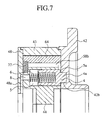
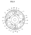
- a vane type hydraulic actuator according to the third embodiment of the present invention is explained below, referring to Figs.7 to 9.
- Reference numeral 48a in Fig.7 denotes a fluid channel disposed on the contacting surface of the cover 48, which rotates together with the case 43.
- the rotor 44 contacts with this contacting surface and slides along it. Only when the retaining second stopper pin 4 is engaging with the second engaging recess 42b and the rotor 44 is retained, a fluid channel 8 behind the rotor 44 communicates with the fluid channel 48a so that the space behind the rotor 4 including the second pin holding hole 5 is opened to the atmosphere.
- fluid channel 48a In addition to the fluid channel 48a, another fluid channel (not shown) is disposed in the cover 48, which is connected to a similar fluid channel 7 for the system of the guide stopper pin 1.
- the structure and the function of the fluid channel is identical to the fluid channel 48a, thus their explanations are omitted.
- the cross sectional area of the guide stopper pin 1 is not always equal to that of the retaining stopper pin 4.
- the cross sectional area of the guide stopper pin 1, shown in Fig.9 is smaller compared to that of the retaining stopper pin 4. Otherwise, the cross sectional area of the guide stopper pin 1 can be larger than that of the retaining stopper pin 4.
- advantages can be obtained in that the retaining stopper pin 4 and the guide stopper pin 1 can be smoothly displaced from a position retaining the rotor 44 to a retaining releasing position. Because a fluid channel 48a for the system of the retaining stopper pin 4 and a fluid channel (not shown) for the system of the guide stopper pin 1 are disposed on the contacting surface of the cover 48, where the rotor 44 contacts and slides along it, so that, only when the rotor 44 is locked, the fluid channels can, respectively, communicate with the fluid channel 8 in the system for the retaining stopper pin 4 and the fluid channel (not shown) in the system for the guide stopper pin 1.
- Another advantage is that miss-assembling of the guide stopper pin 1 and the retaining stopper pin 4 in the fabrication process can be avoided, when the cross-sectional area of the guide stopper pin 1 and that of the retaining stopper pin 4 are different.
- miss-assembling of the retaining stopper pin 4 instead of the guide stopper pin 1, into the first pin holding hole 2 corresponding to tapered first engaging recess 42a can be prevented.
- the efficiency of the assembling of the components of the apparatus can be improved.
- Reference numeral 1c in Fig.10 denotes a first engaging boss disposed at an end in the longitudinal direction of the guide stopper pin 1.
- the first engaging boss 1c is formed as a parallel pin.
- the first engaging boss 1c engages into a first engaging recess 42c disposed on the contacting surface of the housing 42 having a diameter larger than that of the first engaging boss 1c.
- the rotor 44 contacts with this contacting surface and slides on it.
- the first engaging boss 1c contacts with a friction increasing member 9 disposed in the base region of the first engaging recess 42c.
- the first engaging boss disposed at an end of the guide stopper pin 1 is formed as a parallel pin; the diameter of the first engaging recess 42c, into which the first engaging boss 1 enters, is larger than that of the first engaging boss 1c; a friction increasing member 9 is disposed in the base region of the first engaging recess 42c; and the tip portion of the first engaging boss 1c contacts with the friction increasing member 9.
- the first engaging boss 1c of the guide stopper pin 1 is formed as a parallel pin; the diameter of the first engaging recess 42c is larger than the diameter of the first engaging boss 1c, which enters into the first engaging recess 42c; a friction increasing member 9 is disposed in the base portion of the first engaging recess 42c; and the first engaging boss 1c contacts with the friction increasing member 9.
- a pin holder 11 is installed in a recessed groove 10 disposed on the contacting surface of the housing 42, which rotates together with the case 43.
- the rotor 44 contacts with the contacting surface and slides along it.
- the pin holder 11 has a second engaging recess portion 42d, which is tapered so that the engaging boss 1a of the guide stopper pin 1 can enter in it and disengage from it.
- the pin holder 11 can slide in the recessed groove 10.
- a pair of balance springs 12A, 12B are disposed in the recessed groove 10 at both sides of the pin holder 11.
- the balance springs functions as a resilient holding means for holding the pin holder 11 so that the pin holder 11 can move in the radial direction of the rotor 44.
- the recessed groove 10 is covered by a cover 13, which has an opening 13a communicating with the second engaging recess portion 42d.
- the diameter of the opening 13a is larger than the diameter of the second engaging recess portion 42d at the larger diameter side.
- the inner surface of the cover 13 is coplanar with the inner surface of the housing 42(the contacting surface of the rotor 44). Otherwise, the pair of the balance springs 12A, 12B can be arranged so that the pin holder 11 can move in the rotation direction of the rotor 44.
- the other structure and function of the fifth embodiment are identical to those of the first embodiment.
- the guide stopper pin 1 When the rotor 44 is locked, the guide stopper pin 1 is pushed by the resilient spring 3 so that the first engaging boss 1a of the guide stopper pin 1 enters into the first engaging recess 42d through the opening 13a and the guide stopper pin 1 is temporarily locked to the housing 42, in a similar way as in the first embodiment.
- the first engaging boss 1a of the guide stopper pin 1 can enter easily into the first engaging recess 42d and can be held at a center portion of the balance springs 12A, 12B, that is an equilibrium position of the resilient force of the balance springs. After the temporal locking, the relative velocity between the rotor 44 and the housing 42 decreases so that the retaining stopper pin 4 can move smoothly and securely in the direction to lock the rotor 44.
- the features of the fifth embodiment are such that the first engaging boss 1a of the guide stopper pin 1 is tapered; a pin holder 11 having a tapered engaging recess 42d, in which the first engaging boss 1a can engage, is installed in a groove 10 disposed in the housing 42; the pin holder 11 is resiliently held by a pair of balance springs 12A, 12B.
- the first engaging boss 1a of the guide stopper pin 1 can easily enter into the first engaging recess 42d in the pin holder 11 so that the rotor 44 can be smoothly locked temporarily, and the relative velocity between the rotor 44 and the housing 42 decreases because of the temporal locking of the rotor 44.
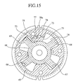
- the vane type hydraulic actuator according to the sixth embodiment is explained, referring to Figs. 13 to 16. Components identical or corresponding to those explained referring to Figs. 1-9 are referred to the same reference numerals, and their explanations are omitted.
- a first pin holding hole 102 and a second pin holding hole 105 penetrate a shoe 71 of the case 43 in the radial direction.
- the first and second holding holes 102, 105 are arranged side by side in the direction of the axis of the rotor 44.
- the first pin holding hole 102 receives a guide stopper pin 101, which can slide in the radial direction in the hole 102.
- the guide stopper pin has a first engaging boss 101a formed as a tapered pin at its radially inner end portion and a spring holding hole 101b which has an opening at its radially outer end.
- the guide stopper pin 101 functions as a guide locking means for securely guiding the rotor 44 to a predetermined position to engage with the housing.
- the guide stopper pin 101 is pushed towards the rotor 44 by a first spring 103.
- the first spring 103 is held by a plug 102a, which is plugged into the radially outer opening of the first pin holding hole 102.
- a first engaging recess 142a is disposed in the hub portion of the rotor 44, which contacts with the shoe 71, having the first pin holding hole 102, and slides along it.
- the first engaging recess 142a is tapered so that the inner diameter increases gradually outwardly.
- the first engaging boss 101a of the guide stopper pin 101 can enter into the first engaging recess 142a and exit from there.
- the correction facilitates the engagement of the retaining locking means, as will be explained below.
- the second pin holding hole 105A receives a retaining stopper pin 104, which can slide in the radial direction of the case 43.
- the retaining stopper pin has a second engaging boss 104a, formed as a parallel pin with small diameter, in its radially inner portion, and a second spring holding hole 104b, which has an opening at its radially outer end portion.
- the retaining stopper pin 104 functions as a retaining locking means for retaining securely the rotor 44 at a predetermined position.
- the retaining stopper pin 104 is pushed towards the rotor 44 by a second spring 106.
- the outer opening of the second spring holding hole 104b is plugged by a plug 105a, which holds the second spring 106.
- a second engaging recess 142b is disposed in the hub portion of the rotor 44, with which the shoe 71 having the retaining stopper pin 104 contacts.
- the second engaging recess 142b is arranged adjacently to the first engaging recess 142a, which belongs to the system for the guide stopper pin 101, and is formed as a cylindrical hole matched with the second engaging boss 104a so that the second engaging boss 104a of the retaining stopper pin 104 can enter and exit from it.
- the resilient force of the first spring 103 for the guide stopper pin 101 is designed to be stronger than that of the second spring 106 for the retaining stopper pin 104.
- each of the vane 66 having the guide stopper pin 1 and the vane 64 having the retaining stopper pin 4 has an oil channel for releasing the locking (oil channel 58a, 58b, communicating oil channel 75, and groove), and an oil channel switching means (slide plate 77).
- the guide stopper pin 101 and the retaining stopper pin 104 have a common lock releasing oil pressure channel (oil channel 58a, communicating channel 75, and groove 76) and an oil channel switching means (slide plate 77) on a shoe 71 projecting towards the rotor shaft. And the guide stopper pin 101 and the retaining stopper pin 104 are simultaneously activated.
- the function of these lock releasing oil pressure channel and the oil channel switching means are substantially identical to those in the first embodiment. Thus their explanation is omitted.
- the oil channel 58a of the lock releasing oil channel supplies oil pressure, which is delivered either from the oil chambers for timing retard 73 and the for timing advance 74, to the guide stopper pin 101 and the retaining stopper pin 104.
- the oil pressure urges the guide stopper pin 101 and the retaining stopper pin 104 in the direction resisting the resilient force of the first and second springs 103, 106.
- the first engaging boss 101a of the guide stopper pin 101 and the second engaging boss 104a of the retaining stopper pin 104 are not always positioned exactly aligned to the corresponding first and second engaging recesses 142a, 142b, namely they can be offset a little from a regular engaging position.
- the first engaging boss 101a When the offset is within the difference between the diameter of the smaller diameter side tip portion of the first engaging boss 10a of the guide stopper pin 101, which is formed as a tapered pin, and the diameter of the opening of the tapered first engaging recess 142a at the largest end, the first engaging boss 101a can be pushed into the first engaging recess 142a by the resilient force of the first spring 103 urging the guide stopper pin 101. As a result, the offset can be corrected.
- the second engaging boss 104a which is formed as a cylindrical pin, of the retaining stopper pin 104 and the cylindrically formed second engaging recess 142b align to each other, then the cylindrically formed second engaging boss 104a enters into the cylindrically formed second engaging recess 142b, due to the resilient force of the second spring 106 urging the retaining stopper pin 104. Finally, the rotor 44 can be locked to the case 43.
- the resilient force of the first spring 103 of the guide stopper pin 104 can be designed to be larger than that of the retaining stopper pin 104.
- the oil pressure which urges commonly the guide stopper pin 101 and the retaining stopper pin 104
- the first and second engaging bosses 101a, 104a and the first and second engaging recesses 142a, 142b are not aligned
- the first engaging boss 101a of the guide stopper pin 101 enters into the first engaging recess 142a, because the resilient force of the first spring 103 of the guide stopper pin 101 is larger than that of the second spring 106 of the retaining stopper pin 104.
- the second engaging boss 104a of the retaining stopper pin 104 and the second engaging recess 142b align to each other, and the second engaging boss 104a can smoothly enter into the second engaging recess 142a.
- advantages can be obtained in that the efficiency of the assembling in the production process of the vane type hydraulic actuator is improved, because the guide stopper pin 101 and the retaining stopper pin 104 are disposed on the shoe 71 so as to be adjacent to each other in the direction of the axis of the rotor 44.
- the first engaging boss 101a of the guide stopper pin 101 can enter smoothly into the first engaging recess 142a, because the first engaging boss 101a of the guide stopper pin is tapered and the first engaging recess 142a is tapered so as to allow to receive the first engaging boss 101a, so that the offset of the position of the second engaging boss can be corrected when the first engaging boss 101a enters into the first engaging recess 142a.
- the second engaging boss 104a of the retaining stopper pin 104 can enter smoothly into the second engaging recess 142b, Consequently, the rotor 44 can be locked securely at a predetermined position. Furthermore, the preciseness of the correction of the offset can be improved, because the offset of the retaining stopper pin 104 is corrected by the guide stopper pin 101 disposed at a position very close to the retaining stopper pin 104.
- the guide stopper pin 101 and the retaining stopper pin 104 are disposed on a shoe 71 of the case 43 so as to be arranged side by side in the direction of the axis of the rotor, and is possible to slide in the radial direction of the rotor.
- they can be disposed in one of the vanes 64-67 of the rotor 44 so as to be arranged side by side in the direction of the axis of the rotor 44 and be possible to slide in the radial direction.
- the guide stopper pin 101 as well as the first engaging recess 142a and that of the retaining stopper pin 104 as well as the second engaging recess 142b can have different cross sectional areas.
- the advantages derived from such a structure are identical to that of the third embodiment.
- Figs.16, 17 Components in Figs.16, 17 identical or equivalent to those in Figs. 1 to 9 and 13 to 15 are referred to the same reference numerals, and their explanations are omitted.
- the guide stopper pin 101 and the retaining stopper pin 104 are disposed in a common shoe 71 of case 43 so as to be adjacent in the direction of the rotor 44.
- the guide stopper pin 101(guide locking means) and the retaining stopper pin 104 (retaining locking means) are disposed on different shoes 71, which are located symmetrically in respect with the axis of the rotor 44.
- the guide stopper pin 101 and the retaining stopper pin 104 are configured symmetrically in respect with the axis of the rotor 44 and can slide in the radial direction of the rotor 44.
- the first engaging recess 142a for disengageably receiving the first engaging boss 101a of the guide stopper pin 101 and the second engaging recess 142b for disengageably receiving the second engaging boss 104a of the retaining stopper pin 104 are disposed in the hub portion of the rotor 44 symmetrically in respect with the axis of the rotor 44.
- the longitudinal length of the hydraulic actuator can be shortened compared to that of the sixth embodiment, in which the guide stopper pin 101 and the retaining stopper pin 104 are disposed adjacent in the direction of the rotor axis.
- the guide stopper pin 101 and the retaining stopper pin 104 are disposed symmetrically in respect with the rotor axis, and the first engaging recess 142a for disengageably receiving the first engaging boss 101a of the guide stopper pin 101 and the second engaging recess 142b for disengageably receiving the second engaging boss 104a of the retaining stopper pin 104 are disposed in the hub portion of the rotor 44 symmetrically in respect with the axis of the rotor 44.
- the hydraulic actuator 40 can be downsized.
- the weight of the hydraulic actuator 40 can be balanced, because the guide stopper pin 101 and the retaining stopper pin 104 are disposed symmetrically in respect with the rotor axis, as explained above, therefore the rotation of the actuator 40 can be stabilized.
Priority Applications (1)
| Application Number | Priority Date | Filing Date | Title |
|---|---|---|---|
| EP03023696A EP1384860A3 (fr) | 1998-12-07 | 1999-11-17 | Déphaseur hydraulique à palettes |
Applications Claiming Priority (4)
| Application Number | Priority Date | Filing Date | Title |
|---|---|---|---|
| JP34752398 | 1998-12-07 | ||
| JP34752398 | 1998-12-07 | ||
| JP21247599 | 1999-07-27 | ||
| JP11212475A JP2000230511A (ja) | 1998-12-07 | 1999-07-27 | ベーン式油圧アクチュエータ |
Related Child Applications (1)
| Application Number | Title | Priority Date | Filing Date |
|---|---|---|---|
| EP03023696A Division EP1384860A3 (fr) | 1998-12-07 | 1999-11-17 | Déphaseur hydraulique à palettes |
Publications (3)
| Publication Number | Publication Date |
|---|---|
| EP1008729A2 true EP1008729A2 (fr) | 2000-06-14 |
| EP1008729A3 EP1008729A3 (fr) | 2000-09-27 |
| EP1008729B1 EP1008729B1 (fr) | 2005-01-26 |
Family
ID=26519253
Family Applications (2)
| Application Number | Title | Priority Date | Filing Date |
|---|---|---|---|
| EP99122062A Expired - Fee Related EP1008729B1 (fr) | 1998-12-07 | 1999-11-17 | Actionneur hydraulique à ailettes |
| EP03023696A Withdrawn EP1384860A3 (fr) | 1998-12-07 | 1999-11-17 | Déphaseur hydraulique à palettes |
Family Applications After (1)
| Application Number | Title | Priority Date | Filing Date |
|---|---|---|---|
| EP03023696A Withdrawn EP1384860A3 (fr) | 1998-12-07 | 1999-11-17 | Déphaseur hydraulique à palettes |
Country Status (4)
| Country | Link |
|---|---|
| US (2) | US6302072B1 (fr) |
| EP (2) | EP1008729B1 (fr) |
| JP (1) | JP2000230511A (fr) |
| DE (1) | DE69923417T2 (fr) |
Cited By (17)
| Publication number | Priority date | Publication date | Assignee | Title |
|---|---|---|---|---|
| EP1164255A1 (fr) * | 2000-06-16 | 2001-12-19 | Dr.Ing. h.c.F. Porsche Aktiengesellschaft | Appareil pour régler la phase entre un arbre à cames et une roue motrice d'un moteur à combustion interne |
| EP1170466A3 (fr) * | 2000-07-07 | 2002-01-30 | Dr.Ing. h.c.F. Porsche Aktiengesellschaft | Arbre à cames pour soupapes de moteur à combustion interne |
| EP1178184A1 (fr) * | 2000-07-31 | 2002-02-06 | Toyota Jidosha Kabushiki Kaisha | Appareil de contrôle de la phase des soupapes et méthode pour arrêter un moteur à combustion interne |
| EP1197641A2 (fr) * | 2000-10-11 | 2002-04-17 | Hydraulik Ring GmbH | Dispositif de verrouillage d'un arbre à cames en position de démarrage |
| FR2821644A1 (fr) * | 2001-03-05 | 2002-09-06 | Mitsubishi Electric Corp | Dispositif de commande de calage de soupapes |
| WO2003067034A1 (fr) | 2002-02-09 | 2003-08-14 | Dr. Ing. H.C. F. Porsche Aktiengesellschaft | Dispositif permettant de regler l'angle de rotation d'un arbre a cames d'un moteur a combustion interne par rapport a une roue motrice |
| KR100412709B1 (ko) * | 2001-10-08 | 2003-12-31 | 현대자동차주식회사 | 차량의 베인형 연속 가변 밸브 타이밍제어장치 |
| EP1491728A2 (fr) * | 2003-06-25 | 2004-12-29 | Aisin Seiki Kabushiki Kaisha | Déphaseur d'arbre à cames |
| EP1568856A1 (fr) * | 2004-02-27 | 2005-08-31 | Delphi Technologies, Inc. | Tige de blocage pour déphaseur d'arbes à cames du type à pallettes |
| WO2005108752A1 (fr) * | 2004-05-05 | 2005-11-17 | Daimlerchrysler Ag | Variateur d'arbre a cames hydraulique et procede de montage |
| EP1731722A1 (fr) * | 2005-06-08 | 2006-12-13 | Hydraulik-Ring GmbH | Déphaseur d'arbre à came à rotor de moteur oscillant et fuite hydraulique réduite |
| WO2007048706A1 (fr) * | 2005-10-28 | 2007-05-03 | Schaeffler Kg | Dispositif de réglage d’arbre à cames avec système de verrouillage |
| US7311069B2 (en) | 2003-06-25 | 2007-12-25 | Aisin Seiki Kabushiki Kaisha | Variable valve timing control device |
| EP2492459A3 (fr) * | 2011-02-22 | 2013-01-23 | Schwäbische Hüttenwerke Automotive GmbH | Régulateur de phase d'arbres doté d'un dispositif de verrouillage amélioré |
| CN103946491A (zh) * | 2012-01-16 | 2014-07-23 | 爱信精机株式会社 | 阀开闭时期控制装置 |
| DE10149056B4 (de) * | 2000-10-06 | 2017-11-30 | Denso Corporation | Ventilzeitabstimmungseinstellvorrichtung mit Anschlagkolben |
| WO2018046087A1 (fr) * | 2016-09-08 | 2018-03-15 | HELLA GmbH & Co. KGaA | Appareil et procédé de réglage d'arbre à cames |
Families Citing this family (54)
| Publication number | Priority date | Publication date | Assignee | Title |
|---|---|---|---|---|
| DE19951390A1 (de) * | 1999-10-26 | 2001-05-03 | Schaeffler Waelzlager Ohg | Vorrichtung zur hydraulischen Drehwinkelverstellung einer Welle relativ zu einem Antriebsrad |
| DE10064222B4 (de) * | 1999-12-24 | 2006-02-09 | Aisin Seiki K.K., Kariya | Verstellbares Ventilsteuersystem |
| DE10013479A1 (de) * | 2000-03-18 | 2001-09-20 | Schaeffler Waelzlager Ohg | Vorrichtung zum Variieren der Ventilsteuerzeiten einer Brennkraftmaschine |
| JP2001355462A (ja) * | 2000-06-09 | 2001-12-26 | Denso Corp | 内燃機関の可変バルブタイミング制御装置 |
| DE10033291A1 (de) * | 2000-07-07 | 2002-01-17 | Porsche Ag | Nockenwelle zur Betätigung von Ventilen einer Brennkraftmaschine |
| JP2002097911A (ja) * | 2000-09-22 | 2002-04-05 | Aisin Seiki Co Ltd | 弁開閉時期制御装置 |
| JP4465846B2 (ja) * | 2000-09-27 | 2010-05-26 | アイシン精機株式会社 | 弁開閉時期制御装置 |
| JP3699645B2 (ja) * | 2000-11-28 | 2005-09-28 | 三菱電機株式会社 | 内燃機関のバルブタイミング制御装置 |
| JP4159241B2 (ja) * | 2000-11-30 | 2008-10-01 | 株式会社デンソー | 内燃機関用バルブタイミング調整装置 |
| US6374788B1 (en) * | 2000-12-25 | 2002-04-23 | Mitsubishi Denki Kabushiki Kaisha | Valve timing control device |
| US6460496B2 (en) * | 2000-12-25 | 2002-10-08 | Mitsubishi Denki Kabushiki Kaisha | Valve timing control device |
| JP2002276311A (ja) * | 2001-03-19 | 2002-09-25 | Mitsubishi Electric Corp | バルブタイミング調整装置 |
| KR100412827B1 (ko) * | 2001-06-20 | 2003-12-31 | 현대자동차주식회사 | 자동차 엔진의 밸브타이밍 가변장치 |
| US6782856B2 (en) * | 2002-04-09 | 2004-08-31 | Ford Global Technologies, Llc | Camshaft accumulator |
| JP3755655B2 (ja) * | 2002-04-23 | 2006-03-15 | 三菱電機株式会社 | 内燃機関のバルブタイミング制御装置 |
| DE10223431B4 (de) * | 2002-05-25 | 2004-07-08 | Ina-Schaeffler Kg | Brennkraftmaschine mit zumindest zwei nebeneinander angeordneten, jeweils mit einer Vorrichtung zur Drehwinkelverstellung gegenüber einer Kurbelwelle ausgebildeten Nockenwellen |
| US6932037B2 (en) * | 2003-01-28 | 2005-08-23 | Borgwarner Inc. | Variable CAM timing (VCT) system having modifications to increase CAM torsionals for engines having limited inherent torsionals |
| JP4177297B2 (ja) * | 2004-06-25 | 2008-11-05 | 株式会社日立製作所 | 内燃機関のバルブタイミング制御装置 |
| JP4005068B2 (ja) * | 2004-08-31 | 2007-11-07 | 株式会社日立製作所 | 内燃機関のバルブタイミング制御装置及びその組立方法 |
| JP4016020B2 (ja) * | 2004-08-31 | 2007-12-05 | 株式会社日立製作所 | 内燃機関のバルブタイミング制御装置 |
| JP4570977B2 (ja) * | 2005-02-14 | 2010-10-27 | 日立オートモティブシステムズ株式会社 | 内燃機関のバルブタイミング制御装置及びその組付方法 |
| US7226038B1 (en) * | 2005-03-25 | 2007-06-05 | Jon Wickstrom | Load arrestor, lifting system and method |
| DE102005036917A1 (de) * | 2005-08-05 | 2007-02-08 | Schaeffler Kg | Verriegelungseinrichtung für einen Nockenwellenversteller einer Brennkraftmaschine |
| DE102005044809A1 (de) * | 2005-09-20 | 2007-03-29 | Daimlerchrysler Ag | Nockenwellenstellvorrichtung |
| DE202007005283U1 (de) * | 2007-03-07 | 2007-07-12 | Abi Gmbh | Schwingungserreger |
| DE102007011282A1 (de) * | 2007-03-08 | 2008-09-11 | Schaeffler Kg | Vorrichtung zur Nockenwellenverstellung einer Brennkraftmaschine |
| JP4950949B2 (ja) * | 2008-06-19 | 2012-06-13 | 日立オートモティブシステムズ株式会社 | 内燃機関のバルブタイミング制御装置 |
| JP5029671B2 (ja) | 2009-10-15 | 2012-09-19 | 株式会社デンソー | バルブタイミング調整装置 |
| DE102009050779B4 (de) | 2009-10-27 | 2016-05-04 | Hilite Germany Gmbh | Schwenkmotornockenwellenversteller mit einer Reibscheibe und Montageverfahren |
| DE102009054049B4 (de) * | 2009-11-20 | 2020-08-27 | Schaeffler Technologies AG & Co. KG | Nockenwellenverstellanordnung |
| JP5843422B2 (ja) * | 2009-12-10 | 2016-01-13 | 株式会社ブリヂストン | クローラ走行装置 |
| DE102010005602A1 (de) * | 2010-01-25 | 2011-07-28 | Schaeffler Technologies GmbH & Co. KG, 91074 | Nockenwellenversteller |
| DE102010045358A1 (de) | 2010-04-10 | 2011-10-13 | Hydraulik-Ring Gmbh | Schwenkmotornockenwellenversteller mit einem Hydraulikventil |
| DE102010019005B4 (de) | 2010-05-03 | 2017-03-23 | Hilite Germany Gmbh | Schwenkmotorversteller |
| US8397689B2 (en) | 2010-05-17 | 2013-03-19 | GM Global Technology Operations LLC | Fuel pump tappet/roller follower lubrication |
| DE102010061337B4 (de) | 2010-12-20 | 2015-07-09 | Hilite Germany Gmbh | Hydraulikventil für einen Schwenkmotorversteller |
| JP5760973B2 (ja) * | 2011-11-15 | 2015-08-12 | トヨタ自動車株式会社 | 内燃機関の可変動弁装置 |
| JP5310826B2 (ja) * | 2011-11-16 | 2013-10-09 | 株式会社デンソー | バルブタイミング調整装置 |
| JP5781910B2 (ja) * | 2011-12-09 | 2015-09-24 | 日立オートモティブシステムズ株式会社 | 内燃機関のバルブタイミング制御装置 |
| JP5563007B2 (ja) * | 2012-03-29 | 2014-07-30 | 株式会社クボタ | クローラ走行装置 |
| JP6091115B2 (ja) * | 2012-09-07 | 2017-03-08 | 日立オートモティブシステムズ株式会社 | 内燃機関のバルブタイミング制御装置及びその製造方法 |
| JP6093134B2 (ja) * | 2012-09-24 | 2017-03-08 | 日立オートモティブシステムズ株式会社 | 内燃機関のバルブタイミング制御装置 |
| JP6225725B2 (ja) * | 2013-03-11 | 2017-11-08 | アイシン精機株式会社 | 弁開閉時期制御装置 |
| US8893677B2 (en) * | 2013-03-14 | 2014-11-25 | Borgwarner Inc. | Dual lock pin phaser |
| US9133735B2 (en) | 2013-03-15 | 2015-09-15 | Kohler Co. | Variable valve timing apparatus and internal combustion engine incorporating the same |
| JP5494862B2 (ja) * | 2013-04-23 | 2014-05-21 | 株式会社デンソー | バルブタイミング調整装置 |
| CN105473828B (zh) | 2013-06-19 | 2017-03-08 | 博格华纳公司 | 具有通过油压接合的锁定销的可变凸轮轴定时机构 |
| US11047506B2 (en) | 2013-08-29 | 2021-06-29 | Aventics Corporation | Valve assembly and method of cooling |
| US10072773B2 (en) | 2013-08-29 | 2018-09-11 | Aventics Corporation | Valve assembly and method of cooling |
| WO2015031587A1 (fr) | 2013-08-29 | 2015-03-05 | Llc Vector Horizon Technologies | Actionneur électro-hydraulique |
| JP6157308B2 (ja) * | 2013-10-18 | 2017-07-05 | 日立オートモティブシステムズ株式会社 | 内燃機関のバルブタイミング制御装置 |
| CN109209548B (zh) | 2017-06-30 | 2022-01-25 | 博格华纳公司 | 具有两个锁定位置的可变凸轮轴正时装置 |
| CN109989796A (zh) * | 2017-12-29 | 2019-07-09 | 舍弗勒技术股份两合公司 | 叶片式凸轮相位器 |
| DE102021110703A1 (de) | 2021-04-27 | 2022-10-27 | Schaeffler Technologies AG & Co. KG | Nockenwellenversteller mit Oszillationsreduktion zwischen Rotor und Stator, Verfahren zum Steuern oder Regeln eines hydraulischen Nockenwellenverstellers und computerlesbares Medium mit Nockenwellenverstellersteuer- / -regelungsanweisungen |
Citations (4)
| Publication number | Priority date | Publication date | Assignee | Title |
|---|---|---|---|---|
| DE19623818A1 (de) * | 1995-06-14 | 1996-12-19 | Nippon Denso Co | Steuervorrichtung zum Variieren einer Dreh- oder Winkelphase zwischen zwei drehenden Wellen, vorzugsweise anwendbar auf eine Ventilsteuerzeiten-Steuervorrichtung für einen Verbrennungsmotor |
| EP0821138A1 (fr) * | 1996-07-23 | 1998-01-28 | Aisin Seiki Kabushiki Kaisha | Dispositifs de commande du calage des soupapes |
| EP0859130A1 (fr) * | 1997-02-14 | 1998-08-19 | Toyota Jidosha Kabushiki Kaisha | Dispositif de régulation de commande de soupape pour moteur à combustion interne |
| DE19914767A1 (de) * | 1998-03-31 | 1999-10-14 | Aisin Seiki | Ventilzeitsteuerungseinrichtung |
Family Cites Families (8)
| Publication number | Priority date | Publication date | Assignee | Title |
|---|---|---|---|---|
| JP3075337B2 (ja) | 1995-06-14 | 2000-08-14 | 株式会社デンソー | 内燃機関用バルブタイミング調整装置 |
| JP3888395B2 (ja) * | 1996-07-11 | 2007-02-28 | アイシン精機株式会社 | 弁開閉時期制御装置 |
| JPH10159515A (ja) * | 1996-11-29 | 1998-06-16 | Toyota Motor Corp | 内燃機関のバルブタイミング制御装置 |
| DE69731012T2 (de) * | 1996-12-12 | 2005-11-17 | Aisin Seiki K.K., Kariya | Ventilsteuerungseinrichtung |
| JP3620684B2 (ja) * | 1997-01-31 | 2005-02-16 | 株式会社デンソー | 内燃機関用バルブタイミング調整装置 |
| JP3760566B2 (ja) * | 1997-06-05 | 2006-03-29 | アイシン精機株式会社 | 弁開閉時期制御装置 |
| US6173687B1 (en) * | 1997-11-14 | 2001-01-16 | Mitsubishi Denki Kabushiki Kaisha | Hydraulic apparatus for adjusting the timing of opening and closing of an engine valve |
| JP3918971B2 (ja) * | 1998-04-27 | 2007-05-23 | アイシン精機株式会社 | 弁開閉時期制御装置 |
-
1999
- 1999-07-27 JP JP11212475A patent/JP2000230511A/ja active Pending
- 1999-11-15 US US09/439,281 patent/US6302072B1/en not_active Expired - Fee Related
- 1999-11-17 DE DE69923417T patent/DE69923417T2/de not_active Expired - Fee Related
- 1999-11-17 EP EP99122062A patent/EP1008729B1/fr not_active Expired - Fee Related
- 1999-11-17 EP EP03023696A patent/EP1384860A3/fr not_active Withdrawn
-
2001
- 2001-07-16 US US09/904,861 patent/US6332439B2/en not_active Expired - Fee Related
Patent Citations (4)
| Publication number | Priority date | Publication date | Assignee | Title |
|---|---|---|---|---|
| DE19623818A1 (de) * | 1995-06-14 | 1996-12-19 | Nippon Denso Co | Steuervorrichtung zum Variieren einer Dreh- oder Winkelphase zwischen zwei drehenden Wellen, vorzugsweise anwendbar auf eine Ventilsteuerzeiten-Steuervorrichtung für einen Verbrennungsmotor |
| EP0821138A1 (fr) * | 1996-07-23 | 1998-01-28 | Aisin Seiki Kabushiki Kaisha | Dispositifs de commande du calage des soupapes |
| EP0859130A1 (fr) * | 1997-02-14 | 1998-08-19 | Toyota Jidosha Kabushiki Kaisha | Dispositif de régulation de commande de soupape pour moteur à combustion interne |
| DE19914767A1 (de) * | 1998-03-31 | 1999-10-14 | Aisin Seiki | Ventilzeitsteuerungseinrichtung |
Cited By (29)
| Publication number | Priority date | Publication date | Assignee | Title |
|---|---|---|---|---|
| EP1164255A1 (fr) * | 2000-06-16 | 2001-12-19 | Dr.Ing. h.c.F. Porsche Aktiengesellschaft | Appareil pour régler la phase entre un arbre à cames et une roue motrice d'un moteur à combustion interne |
| US6742484B2 (en) | 2000-06-16 | 2004-06-01 | Ing. H.C.F. Porsche Ag | Device for relative rotational angle adjustment of a cam shaft of an internal combustion engine to a drive wheel |
| EP1170466A3 (fr) * | 2000-07-07 | 2002-01-30 | Dr.Ing. h.c.F. Porsche Aktiengesellschaft | Arbre à cames pour soupapes de moteur à combustion interne |
| KR100427434B1 (ko) * | 2000-07-31 | 2004-04-13 | 도요다 지도샤 가부시끼가이샤 | 내연기관의 밸브타이밍 제어장치 및 그 제어방법 |
| EP1178184A1 (fr) * | 2000-07-31 | 2002-02-06 | Toyota Jidosha Kabushiki Kaisha | Appareil de contrôle de la phase des soupapes et méthode pour arrêter un moteur à combustion interne |
| US6478000B2 (en) | 2000-07-31 | 2002-11-12 | Toyota Jidosha Kabushiki Kaisha | Valve timing control apparatus and method for internal combustion engine |
| DE10149056B4 (de) * | 2000-10-06 | 2017-11-30 | Denso Corporation | Ventilzeitabstimmungseinstellvorrichtung mit Anschlagkolben |
| EP1197641A2 (fr) * | 2000-10-11 | 2002-04-17 | Hydraulik Ring GmbH | Dispositif de verrouillage d'un arbre à cames en position de démarrage |
| EP1197641A3 (fr) * | 2000-10-11 | 2003-01-29 | Hydraulik Ring GmbH | Dispositif de verrouillage d'un arbre à cames en position de démarrage |
| FR2821644A1 (fr) * | 2001-03-05 | 2002-09-06 | Mitsubishi Electric Corp | Dispositif de commande de calage de soupapes |
| KR100412709B1 (ko) * | 2001-10-08 | 2003-12-31 | 현대자동차주식회사 | 차량의 베인형 연속 가변 밸브 타이밍제어장치 |
| WO2003067034A1 (fr) | 2002-02-09 | 2003-08-14 | Dr. Ing. H.C. F. Porsche Aktiengesellschaft | Dispositif permettant de regler l'angle de rotation d'un arbre a cames d'un moteur a combustion interne par rapport a une roue motrice |
| US6941912B2 (en) | 2002-02-09 | 2005-09-13 | Dr. Ing. H.C.F. Porsche Aktiengesellschaft | Device and method for the relative rotational adjustment of a camshaft and a drive wheel of an internal combustion engine |
| US7198013B2 (en) | 2002-02-09 | 2007-04-03 | Dr. Ing. H.C.F. Porsche Aktiengesellschaft | Device and method for the relative rotational adjustment of a camshaft and a drive wheel of an internal combustion engine |
| EP1491728A2 (fr) * | 2003-06-25 | 2004-12-29 | Aisin Seiki Kabushiki Kaisha | Déphaseur d'arbre à cames |
| US7311069B2 (en) | 2003-06-25 | 2007-12-25 | Aisin Seiki Kabushiki Kaisha | Variable valve timing control device |
| EP1491728A3 (fr) * | 2003-06-25 | 2005-11-30 | Aisin Seiki Kabushiki Kaisha | Déphaseur d'arbre à cames |
| US6948467B2 (en) | 2004-02-27 | 2005-09-27 | Delphi Technologies, Inc. | Locking pin mechanism for a vane-type cam phaser |
| EP1568856A1 (fr) * | 2004-02-27 | 2005-08-31 | Delphi Technologies, Inc. | Tige de blocage pour déphaseur d'arbes à cames du type à pallettes |
| WO2005108752A1 (fr) * | 2004-05-05 | 2005-11-17 | Daimlerchrysler Ag | Variateur d'arbre a cames hydraulique et procede de montage |
| US7661397B2 (en) | 2004-05-05 | 2010-02-16 | Daimler Ag | Hydraulic camshaft adjuster and method for assembling the same |
| EP1731722A1 (fr) * | 2005-06-08 | 2006-12-13 | Hydraulik-Ring GmbH | Déphaseur d'arbre à came à rotor de moteur oscillant et fuite hydraulique réduite |
| US7640902B2 (en) | 2005-06-08 | 2010-01-05 | Hydraulik-Ring Gmbh | Rotor for vane-type motor with reduced leakage |
| WO2007048706A1 (fr) * | 2005-10-28 | 2007-05-03 | Schaeffler Kg | Dispositif de réglage d’arbre à cames avec système de verrouillage |
| US7823554B2 (en) | 2005-10-28 | 2010-11-02 | Schaeffler Technologies Gmbh & Co. Kg | Camshaft adjuster with a locking system |
| CN101297102B (zh) * | 2005-10-28 | 2011-01-05 | 谢夫勒两合公司 | 具有闭塞装置的凸轮轴调整器 |
| EP2492459A3 (fr) * | 2011-02-22 | 2013-01-23 | Schwäbische Hüttenwerke Automotive GmbH | Régulateur de phase d'arbres doté d'un dispositif de verrouillage amélioré |
| CN103946491A (zh) * | 2012-01-16 | 2014-07-23 | 爱信精机株式会社 | 阀开闭时期控制装置 |
| WO2018046087A1 (fr) * | 2016-09-08 | 2018-03-15 | HELLA GmbH & Co. KGaA | Appareil et procédé de réglage d'arbre à cames |
Also Published As
| Publication number | Publication date |
|---|---|
| DE69923417D1 (de) | 2005-03-03 |
| US6332439B2 (en) | 2001-12-25 |
| EP1008729B1 (fr) | 2005-01-26 |
| US20010039932A1 (en) | 2001-11-15 |
| US6302072B1 (en) | 2001-10-16 |
| EP1384860A3 (fr) | 2004-03-03 |
| DE69923417T2 (de) | 2005-12-29 |
| EP1384860A2 (fr) | 2004-01-28 |
| JP2000230511A (ja) | 2000-08-22 |
| EP1008729A3 (fr) | 2000-09-27 |
Similar Documents
| Publication | Publication Date | Title |
|---|---|---|
| EP1008729B1 (fr) | Actionneur hydraulique à ailettes | |
| US10145273B2 (en) | Control valve for valve timing control device and valve timing control device for internal combustion engine | |
| US8122863B2 (en) | Camshaft phaser for the inner camshaft of a concentric camshaft assembly | |
| EP0806550B2 (fr) | Dispositif de commande du calage des soupapes | |
| US6170448B1 (en) | Variable valve timing apparatus | |
| US20010039933A1 (en) | Valve timing adjusting device | |
| EP3179143A1 (fr) | Valve oléo-hydraulique, et dispositif de commande de réglage de distribution pour moteur à combustion interne mettant en uvre une valve oléo-hydraulique | |
| US6263843B1 (en) | Valve timing control device of internal combustion engine | |
| EP0821138B1 (fr) | Dispositifs de commande du calage des soupapes | |
| US9046013B2 (en) | Camshaft phase | |
| US6334414B1 (en) | Valve timing adjusting apparatus | |
| JP3174297B2 (ja) | ベーン式油圧アクチュエータ | |
| EP2511535A2 (fr) | Dispositif de commande hydraulique | |
| US20060266318A1 (en) | Valve timing control apparatus and internal combustion engine | |
| US20020040697A1 (en) | Valve timing adjusting device having stopper piston | |
| US5203291A (en) | Valve timing control system for internal combustion engine | |
| WO2016021328A1 (fr) | Valve oléo-hydraulique, et dispositif de commande de réglage de distribution pour moteur à combustion interne mettant en œuvre une valve oléo-hydraulique | |
| US10626760B2 (en) | Valve opening/closing timing control device | |
| US20060260577A1 (en) | Valve timing control apparatus and internal combustion engine | |
| US5513965A (en) | Distributor-type fuel injection pump | |
| US6439183B1 (en) | Valve timing adjusting device | |
| US10570785B2 (en) | Hydrostatic camshaft phaser | |
| EP2363579A1 (fr) | Öldurchflussregelventil mit zwei Rückschlagventilen | |
| JPH11241607A (ja) | 可変動弁機構 | |
| EP2895709A1 (fr) | Ensemble arbre à cames concentrique |
Legal Events
| Date | Code | Title | Description |
|---|---|---|---|
| PUAI | Public reference made under article 153(3) epc to a published international application that has entered the european phase |
Free format text: ORIGINAL CODE: 0009012 |
|
| AK | Designated contracting states |
Kind code of ref document: A2 Designated state(s): DE FR GB IT |
|
| AX | Request for extension of the european patent |
Free format text: AL;LT;LV;MK;RO;SI |
|
| PUAL | Search report despatched |
Free format text: ORIGINAL CODE: 0009013 |
|
| AK | Designated contracting states |
Kind code of ref document: A3 Designated state(s): AT BE CH CY DE DK ES FI FR GB GR IE IT LI LU MC NL PT SE |
|
| AX | Request for extension of the european patent |
Free format text: AL;LT;LV;MK;RO;SI |
|
| 17P | Request for examination filed |
Effective date: 20001027 |
|
| AKX | Designation fees paid |
Free format text: DE FR GB IT |
|
| 17Q | First examination report despatched |
Effective date: 20030707 |
|
| GRAP | Despatch of communication of intention to grant a patent |
Free format text: ORIGINAL CODE: EPIDOSNIGR1 |
|
| GRAS | Grant fee paid |
Free format text: ORIGINAL CODE: EPIDOSNIGR3 |
|
| GRAA | (expected) grant |
Free format text: ORIGINAL CODE: 0009210 |
|
| AK | Designated contracting states |
Kind code of ref document: B1 Designated state(s): DE FR GB IT |
|
| PG25 | Lapsed in a contracting state [announced via postgrant information from national office to epo] |
Ref country code: IT Free format text: LAPSE BECAUSE OF FAILURE TO SUBMIT A TRANSLATION OF THE DESCRIPTION OR TO PAY THE FEE WITHIN THE PRESCRIBED TIME-LIMIT;WARNING: LAPSES OF ITALIAN PATENTS WITH EFFECTIVE DATE BEFORE 2007 MAY HAVE OCCURRED AT ANY TIME BEFORE 2007. THE CORRECT EFFECTIVE DATE MAY BE DIFFERENT FROM THE ONE RECORDED. Effective date: 20050126 Ref country code: FR Free format text: LAPSE BECAUSE OF FAILURE TO SUBMIT A TRANSLATION OF THE DESCRIPTION OR TO PAY THE FEE WITHIN THE PRESCRIBED TIME-LIMIT Effective date: 20050126 |
|
| REG | Reference to a national code |
Ref country code: GB Ref legal event code: FG4D |
|
| REF | Corresponds to: |
Ref document number: 69923417 Country of ref document: DE Date of ref document: 20050303 Kind code of ref document: P |
|
| PG25 | Lapsed in a contracting state [announced via postgrant information from national office to epo] |
Ref country code: GB Free format text: LAPSE BECAUSE OF NON-PAYMENT OF DUE FEES Effective date: 20051117 |
|
| PGFP | Annual fee paid to national office [announced via postgrant information from national office to epo] |
Ref country code: DE Payment date: 20051121 Year of fee payment: 7 |
|
| PLBE | No opposition filed within time limit |
Free format text: ORIGINAL CODE: 0009261 |
|
| STAA | Information on the status of an ep patent application or granted ep patent |
Free format text: STATUS: NO OPPOSITION FILED WITHIN TIME LIMIT |
|
| 26N | No opposition filed |
Effective date: 20051027 |
|
| EN | Fr: translation not filed | ||
| GBPC | Gb: european patent ceased through non-payment of renewal fee |
Effective date: 20051117 |
|
| PG25 | Lapsed in a contracting state [announced via postgrant information from national office to epo] |
Ref country code: DE Free format text: LAPSE BECAUSE OF NON-PAYMENT OF DUE FEES Effective date: 20070601 |