A process for preparing room temperature
vulcanizing (RTV) silicone compositions which when
exposed to moisture crosslink to form elastomers. The
process comprises the steps of (i) feeding into an axial
flow mixing turbine, starting materials comprising (A)
100 parts by weight of polydiorganosiloxanes, (B) 3 to 15
parts by weight of a silane, (C) 5 to 250 parts by weight
of a filler, and (D) 0.01 to 5 parts by weight of a
catalyst; where the axial flow mixing turbine comprises a
casing having a proximal end and a distal end, a shaft
positioned along the casing's longitudinal axis having a
blade which rotates in a direction perpendicular to the
longitudinal axis of the casing, starting material feed
openings installed at the proximal end of the casing so
that the starting materials flow toward the blade and a
discharge opening positioned at the distal end of the
casing so to discharge mixed materials; (ii) mixing (A),
(B), (C) and (D) by rotation of the blade at a rotational
speed to produce a homogeneous mixture having entrained
gasses and volatiles; (iii) introducing the mixture
formed by step (ii) into a vacuum-equipped degassing
apparatus; and (iv) degassing and removing volatiles from
the mixture.
A two-step process for preparing RTV silicone
compositions is described in U.S. Patent 4,737,561. The
'561 process, comprises mixing, in a first step,
crosslinkable diorgano(poly)siloxanes, filler(s) and
either catalyst(s) or crosslinking agent(s) and a part or
all of the optional additives to be used in a
continuously operating closed mixer. Then in a second
step, metering the crosslinking agent and/or catalyst(s)
not added in the first step and the remainder of the
optional additives to be used into the mixture thus
obtained in an oscillating pilgrim-step kneader where the
mixture is homogenized and degassed. This patent
requires the crosslinker and catalyst be added in
separate steps.
A one-step process for preparing RTV silicone
compositions is described in EP 0 739 652. The `652
process comprises continuously feeding 100 parts by
weight of a diorganopolysiloxane with a viscosity at
25°C. of 0.1 to 500 Pa-s that contains at least 2
silicon-bonded hydroxyl groups or hydrolyzable groups in
each molecule; 1 to 30 parts by weight of an organosilane
that contains at least 2 silicon-bonded hydrolyzable
groups in each molecule or the partial hydrolysis
condensate thereof; 1 to 200 parts by weight of an
inorganic filler in powder form and 0 to 10 parts by
weight of a cure-accelerating catalyst into a continuous
mixing apparatus. The continuous mixing apparatus has
starting material feed openings installed at its top, a
discharge opening installed at its bottom and a rotating
disk installed within a casing and the ingredients are
therein mixed by the rotation of the rotating disk. The
resulting mixture is thereafter continuously introduced
into a vacuum mechanism-equipped degassing apparatus in
which the water fraction present in the mixture is
removed under reduced pressure. Although this patent
describes a one step process for making an RTV
composition, the resulting composition has poor
appearance due to inadequate dispersion of the filler.
For convenience and manufacturing ease, it
would be useful to be able to manufacture RTV silicone
compositions having improved appearance in a mixer where
the crosslinker and catalyst may be added in a single
step. An object of the present invention is to prepare
RTV silicone compositions having improved appearance in a
axial flow mixing turbine where the crosslinker and
catalyst are added into the composition in a single step.
The present invention is a process for
preparing room temperature vulcanizing (RTV) silicone
compositions which when exposed to moisture crosslink to
form elastomers. The process comprises the steps of (i)
feeding into an axial flow mixing turbine, starting
materials comprising (A) 100 parts by weight of
polydiorganosiloxanes, (B) 3 to 15 parts by weight of a
silane, (C) 5 to 250 parts by weight of a filler and (D)
0.01 to 5 parts by weight of a catalyst; where the axial
flow mixing turbine comprises a casing having a proximal
end and a distal end, a shaft positioned along the
casing's longitudinal axis having a blade which rotates
in a direction perpendicular to the longitudinal axis of
the casing, starting material feed openings installed at
the proximal end of the casing so that the starting
materials flow toward the blade and a discharge opening
positioned at the distal end of the casing so to
discharge mixed materials; (ii) mixing (A), (B), (C) and
(D) by rotation of the blade at a rotational speed to
produce a homogeneous mixture having entrained gasses and
volatiles; (iii) introducing the mixture formed by step
(ii) into a vacuum-equipped degassing apparatus; and (iv)
degassing and removing volatiles from the mixture.
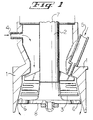
Figure 1 illustrates a cross-sectional view of
a preferred embodiment of an axial flow mixing turbine
used for preparing RTV silicone compositions. The axial
flow mixing turbine comprises a casing (1) having a
proximal end (7) and a distal end (8), a shaft 2
positioned along the casing's longitudinal axis having a
blade (3) which rotates in a direction perpendicular to
the longitudinal axis of the casing, solids starting
material feed openings (4) and liquid starting material
feed openings (5) installed at the proximal end of the
casing so that the starting materials flow toward the
blade and a discharge opening (6) formed at the distal
end of the casing between the casing wall and the blade.
The present invention is a process for
preparing RTV silicone compositions which when exposed to
moisture crosslink to form elastomers. The process
comprises the steps of
Component (A) used in the present process
comprises polydiorganosiloxanes having on average at
least 1.2 chain terminations per molecule described by
the formula (I) or (II). The polydiorganosiloxanes may
be linear or branched and may be homopolymers, copolymers
or terpolymers. The viscosity of the
polydiorganosiloxanes is not critical and the
polydiorganosiloxanes may be a single species or a
mixture of different polydiorganosiloxanes so long as the
polydiorganosiloxanes have on average at least 1.2 chain
terminations per molecule described by formula (I) or
(II).
The repeating units of the polydiorganosiloxanes
of Component (A) are siloxy units such as
described by the formula R1 sSiO(4-s)/2, where each R1 is
an independently selected monovalent hydrocarbon radical
having 1 to 18 carbon atoms; and s is 0, 1 or 2. The
monovalent hydrocarbon radicals represented by R1 may be
substituted or unsubstituted. Examples of monovalent
hydrocarbon radicals having 1 to 18 carbon atoms include
alkyl radicals such as methyl, ethyl, hexyl, 3,3,3-trifluoropropyl,
chloromethyl and octadecyl; alkenyl
radicals such as vinyl, allyl and butadienyl; cycloalkyl
radicals such as cyclobutyl, cyclopentyl and cyclohexyl;
cycloalkenyl radicals such as cyclopentenyl and
cyclohexenyl; aryl radicals such as phenyl and xylyl;
aralkyl radicals such as benzyl; and alkaryl radicals
such as tolyl. The preferred polydiorganosiloxanes of
Component (A) have repeating units described by the
formula -(R1 sSiO(4-s)/2)f-, where each R1 is an
independently selected monovalent hydrocarbon radical
having 1 to 6 carbon atoms, s is 2 and f is a value such
that the polydiorganosiloxanes have a viscosity within a
range of 0.5 to 3000 Pas at 25°C. More preferably each
R1 is independently selected from methyl or ethyl and the
polydiorganosiloxanes have a viscosity within a range of
5 to 150 Pa·s at 25°C.
The polydiorganosiloxanes of Component (A) have
on average at least 1.2 chain terminations per molecule
represented by formula (I) ie.-SiR1 2OH or on average at
least 1.2 chain terminations per molecule represented by
formula (II) ie. -SiR1 xY3-x where R1, Y and x are as
defined above. Preferably, the polydiorganosiloxanes of
Component (A) have on average at least 1.5 chain
terminations per molecule represented by formula (I) or
on average at least 1.5 chain terminations per molecule
represented by formula (II).
In formulas (I) and (II) each R1 is an
independently selected monovalent hydrocarbon radical
having 1 to 18 carbon atoms. Examples of monovalent
hydrocarbon radicals represented by R1 are as described
above.
In formula (II) each Y is independently
selected from alkoxy, acyloxy, ketoximo, aminoxy, amido
or amino. Examples of alkoxy groups include methoxy,
ethoxy; iso-propoxy, butoxy, cyclohexoxy, phenoxy, 2-chloroethoxy,
3,3,3-trifluoropropoxy, 2-methoxyethoxy and
p-methoxyphenoxy. Examples of acyloxy groups include
acetoxy, propionoxy, benzoyloxy and cyclohexoyloxy.
Examples of ketoximo groups include dimethylketoximo,
methylethylketoximo, methylpropylketoximo,
methylbutylketoximo and diethylketoximo. Examples of
aminoxy groups include diethylaminoxy, dimethylaminoxy,
ethylmethylaminoxy and ethylphenylaminoxy. Examples of
amido groups include N-methylacetamido and N-methylbenzamido.
Examples of amino groups include -NH2,
dimethylamino, diethylamino, ethylmethylamino,
diphenylamino, methylphenylamino and dicyclohexylamino.
Preferably, each Y is an independently selected alkoxy
group. More preferably, each Y is an independently
selected alkoxy group having 1 to 4 carbon atoms.
Subscript x in formula (II) is 0 or 1 and is
preferably 0.
In a preferred embodiment for Component (A)
when Y is an alkoxy group, a spacer group Z may be bonded
to the silicon atom of a chain termination described by
formula (II) thereby forming a group described by
-Z-SiR
1 xY
3-x. Each spacer group Z is independently
selected from divalent hydrocarbon radicals having 2 to
18 carbon atoms and a combination of divalent hydrocarbon
radicals and siloxane segments described by the formula
where R
1 is as defined above, each G is an independently
selected divalent hydrocarbon radical having 2 to 18
carbon atoms and c is a whole number from 1 to 6.
The divalent hydrocarbon radicals of Z and G
may be substituted or unsubstituted. Examples of the
divalent hydrocarbon radicals having 2 to 18 carbon atoms
of Z and G include alkylene radicals such as ethylene,
methylmethylene, propylene, butylene, pentylene,
hexylene, 3,3,3-trifluoropropylene, chloromethylene and
octadecylene; alkylene radicals such as vinylene,
allylene and butadienylene; cycloalkylene radicals such
as cyclobutylene, cyclopentylene and cyclohexylene;
cycloalkenylene radicals such as cyclopentenylene and
cyclohexenylene; arylene radicals such as phenylene and
xylylene; aralkylene radicals as benzylene; and
alkarylene radicals such as tolylene.
When Z is a combination of divalent hydrocarbon
radicals and siloxane segments as described above, each G
is preferably an alkylene radical and each G is more
preferably an alkylene radical having 2 to 6 carbon
atoms. Preferably, Z is a divalent hydrocarbon radical
having 2 to 18 carbon atoms. It is more preferred for Z
to be an alkylene radical, with an alkylene radical
having 2 to 6 carbon atoms being most preferred.
Since the polydiorganosiloxanes of Component
(A) are required to have on average at least 1.2 chain
terminations per molecule described by formula (I) or
(II), some polydiorganosiloxanes may contain other types
of chain terminations. Preferably, this other type of
chain termination comprises an organosilyl chain
termination described by R2 3-Si-, where each R2 is an
independently selected monovalent hydrocarbon radical
having 1 to 18 carbon atoms. Examples of R2 are as
described above for R1. Preferably, each R2 is an
independently selected monovalent hydrocarbon radical
having 1 to 8 carbon atoms. More preferably, each R2 is
independently selected from methyl, ethyl, vinyl and
phenyl. Examples of organosilyl chain terminations
include trimethylsilyl, triethylsilyl, vinyldimethylsilyl
and vinylmethylphenylsilyl.
The polydiorganosiloxanes of Component (A)
having on average at least 1.2 chain terminations per
molecule represented by formula (I) and (II) useful in
the present process are well known in the art and are
illustrated by U.S. Patents 3,151,099; 3,161,614;
3,175,993; 3,334,067; 4,871,827; 4,657,967; 4,898,910;
4,956,435; 4,973,623; 3,817,909; 3,996,184; 4,822,830 and
3,077,465.
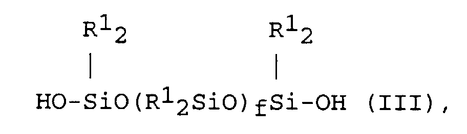
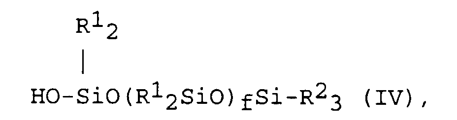
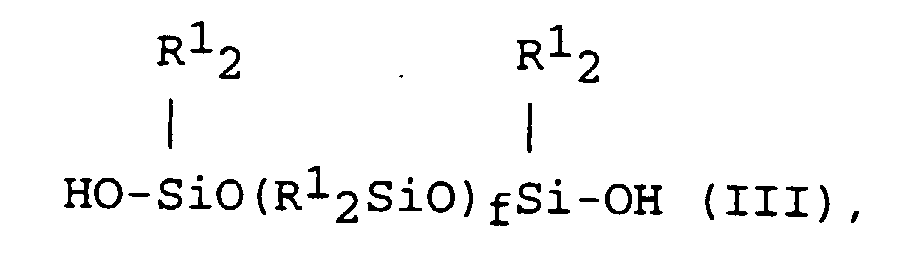
Preferred polydiorganosiloxanes within the
scope of Component (A), are described, for example, by
the formula
and by mixtures of polydiorganosiloxanes described by
formula (III) and polydiorganosiloxanes described by
formula
where R
1, R
2 and f are as defined above.
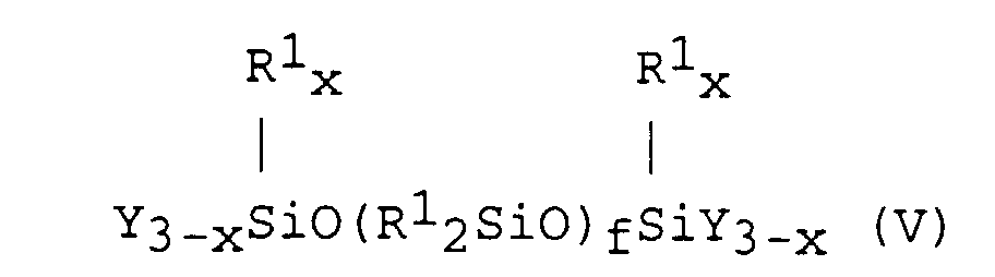
Other preferred polydiorganosiloxanes within
the scope of Component (A), are described, for example,
by the formula
and by mixtures of the polydiorganosiloxanes described by
formula (V) and polydiorganosiloxanes described, for
example, by the formula
where R
1, R
2, x and f are as defined above and each Y is
an independently selected alkoxy group.
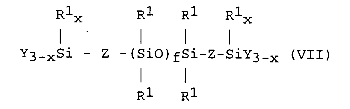
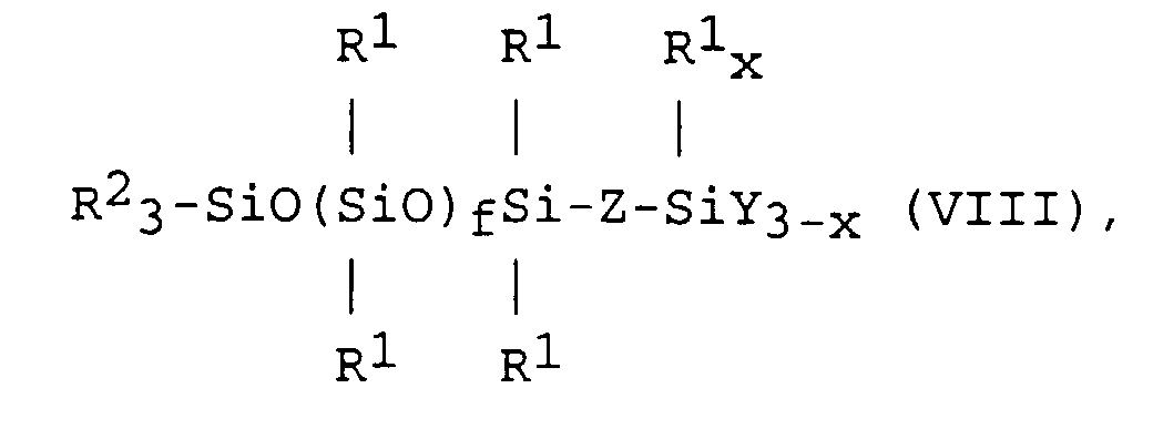
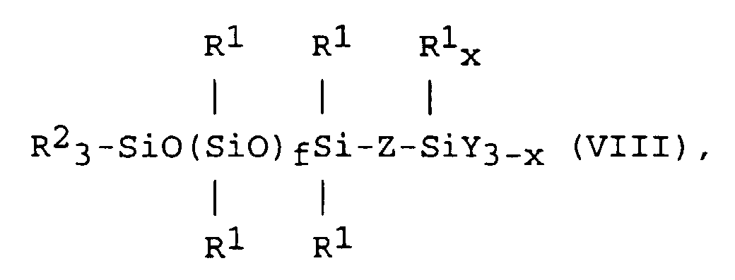
More preferred polydiorganosiloxanes within the
scope of Component (A), include those described for
example, by the formula
and mixtures of the polydiorganosiloxanes described by
formula (VII) and polydiorganosiloxanes described, for
example, by the formula
where R
1, R
2, Z, x and f are as defined above and each Y
is an independently selected alkoxy group.
When Component (A) comprises mixtures of
polydiorganosiloxanes described by formulas (III) and
(IV), (V) and (VI) or (VII) and (VIII), typically the
polydiorganosiloxanes described by formula (IV), (VI) and
(VIII) respectively will be present in an amount such
that 40 percent or less of the chain terminations of
Component (A) will be organosilyl chain terminations and
preferably such that less than 25 percent of the chain
terminations of Component (A) are organosilyl chain
terminations.
Component (B) used in the present process is a
silane described by formula R1 zSiX4-z, where each R1 is
an independently selected monovalent hydrocarbon radical
having from 1 to 18 carbon atoms; each X is independently
selected from alkoxy, acyloxy, ketoximo, aminoxy, amido
or amino and z is 0, 1 or 2.
Examples of the hydrocarbon radicals
represented by R1 are as described above.
Examples of the alkoxy, acyloxy, ketoximo,
aminoxy, amido and amino groups represented by X include
those described above for Y. Preferably, each X is
independently selected from alkoxy or acyloxy. More
preferably, each X is independently selected from alkoxy
groups having 1 to 8 carbon atoms or acyloxy groups
having 2 to 8 carbon atoms. Most preferably, each X is
independently selected from alkoxy groups having 1 to 4
carbon atoms and acyloxy groups having 2 to 4 carbon
atoms.
Subscript z can be 0, 1 or 2. Preferably z is
1 or 2 with 1 being most preferred.
Component (B) is specifically exemplified by
silanes such as methyltrimethoxysilane, vinyltriethoxysilane,
vinylmethyldiethoxysilane, methyltri(methylethylketoximo)silane,
isobutyltrimethoxysilane, vinyltri-(methylethylketoximo)silane,
phenyltri(methylethylketoximo)silane,
methyltriacetoxysilane, vinyltriacetoxysilane,
phenyltriacetoxysilane, dimethyldiacetoxysilane,
methylethoxydiacetoxysilane,
methyltri(N,N-diethylaminoxy)silane, vinyltri(N,N-diethylaminoxy)silane,
vinyltri(N-cyclohexylamino)silane,
vinyltri(N-methylacetamido)silane, tetraacetoxysilane and
tetra(methylketoximo)silane. The partial hydrolyzates of
these silanes can also be used in the present process.
The amount of silane useful in the RTV silicone
compositions prepared by the present process is from 3 to
15 parts by weight based on the weight of Component (A),
with 5 to 8 parts by weight on the same basis being
preferred. The silane may be a single species or a
mixture of two or more species.
Component (C) used in the present process is a
filler which is selected from those known to be useful in
RTV silicone sealants. The fillers include ground,
precipitated and colloidal calcium carbonates which are
untreated or treated with compounds such as stearate or
stearic acid; reinforcing silicas such as fumed silicas,
precipitated silicas, silica gels and hydrophobed silicas
and silica gels; crushed quartz, ground quartz, alumina,
aluminum hydroxide, titanium dioxide, diatomaceous earth,
iron oxide, carbon black and graphite. Silica and
calcium carbonate are each preferred fillers, in
particular fumed silica and precipitated calcium
carbonate.
The amount of filler added depends upon the
physical properties desired for the RTV silicone
compositions. The amount of filler useful in the RTV
silicone compositions prepared by the present process is
from 5 to 250 parts by weight based on 100 parts by
weight of Component (A). Preferably, the filler is added
in amounts from 8.5 to 150 parts by weight on the same
basis. The filler may be added as a single species or as
a mixture of two or more species.
Component (D) used in the present process is a
catalyst effective for facilitating the room temperature
vulcanizing of the composition. Catalysts useful for
curing the silicone sealant mixtures are dependent upon
the reactive groups on Components (A) and (B) and include
compounds such as metal carboxylates, including iron
octoate, cobalt octoate, manganese octoate, tin
naphthenate and tin octoate; organotin compounds, such as
dibutyltin acetate, dibutyltin octoate and dibutyltin
dilaurate; titanium compounds such as tetraalkyltitanates
including tetraisopropyltitanate, tetra-n-butyltitanate,
tetraoctyltitanate, tetra-tertiary-butyltitanate and
tetra-tertiary-amyltitanate; titanate chelates including
dialkoxyacetylacetonate titanate chelate and dialkoxyethylacetoacetate
titanate chelate, where the alkoxy
group includes isopropoxy or isobutoxy or organosiloxytitanium
compounds; zirconium alkoxides and chelates; and
alkoxyaluminum compounds. It is preferred to use
organotin compounds or titanium compounds. It is more
preferred to use organotin compounds when acyloxy groups
are present in the composition and it is preferred to use
a tetraalkyltitanate or titanate chelate when alkoxy
groups are present in the composition.
The amount of catalyst useful in the RTV
silicone compositions prepared by the process of the
present invention is from 0.01 to 5 parts by weight based
on 100 parts by weight of Component (A). Preferably, the
catalyst is added in amounts from 0.025 to 3 parts by
weight on the same basis. The catalyst may be a single
species or a mixture of two or more species.
Other ingredients which are conventionally used
in RTV silicone compositions such as adhesion promoters,
rheology additives, fungicides, colorants, pigments and
plasticizers can also be added in the present process.
In the present process, appropriate amounts of
Components (A)-(D) and any desired additional ingredients
are fed into an axial flow mixing turbine comprising a
casing having a proximal end and a distal end, a shaft
positioned along the casing's longitudinal axis having a
blade which rotates in a direction perpendicular to the
longitudinal axis of the casing, starting material feed
openings installed at the proximal end of the casing so
that the starting materials flow toward the blade and a
discharge opening positioned at the distal end of the
casing so to discharge mixed materials. The starting
materials are then mixed by rotation of the blade at a
rotational speed to produce a homogeneous mixture having
entrained gasses and volatiles.
Suitable axial flow mixing turbines for the
present process are as described in U.S. Patent 4,737,561
which comprises a casing having a proximal end and a
distal end, a shaft positioned along the casing's
longitudinal axis having a blade which rotates in a
direction perpendicular to the longitudinal axis of the
casing, starting material feed openings installed at the
proximal end of the casing so that the starting materials
flow toward the blade and a discharge opening positioned
at the distal end of the casing so to discharge mixed
materials. A single stage or multi-stage mixing turbine
may be used. A preferred axial flow mixing turbine for
use in the present process is a single stage axial flow
mixing turbine manufactured by Buss AG (MT-170,
Hohenrainstrasse 10; CH-4133 Pratteln 1; Switzerland).
The casing of the axial flow mixing turbine has
a proximal end and a distal end. The casing may be
corrosion resistant and have a clam-shell type structure
allowing for ease of cleaning. The casing may also be
jacketed for cooling.
A shaft is positioned along the casing's
longitudinal axis having a blade which rotates in a
direction perpendicular to the longitudinal axis of the
casing. Preferably, the shaft is centrally positioned
along the casing's longitudinal axis. The blade may have
various geometries and configurations so to create the
desired mixing zone.
Starting material feed openings are installed
at the proximal end of the casing so that the starting
materials flow toward the blade. The blade is operated
at a rotational speed to form a homogeneous mixture
having entrained gasses and volatiles which is discharged
from the mixer through a discharge opening positioned at
the distal end of the casing. A rotational speed is that
speed at which a homogeneous mixture is formed.
Preferably, the blade is operated at a rotational speed
from 500 to 4000 rpm. More preferably, the blade is
operated at a rotational speed from 2000 to 3250 rpm.
The flow and mixing of the starting materials may also be
affected by the gap width. The gap width should enable
the starting materials to be mixed by the blade and then
flow through the mixer to the discharge opening
positioned at the distal end of the casing. As used
herein, the term "gap width" means the distance between
the tip of the blade and the casing of the mixing
turbine. A preferred gap width is in the range from 1 to
11 mm and more preferably is in the range from 2.5 mm to
6.5 mm.
The starting materials are fed to the starting
material feed openings by conventional means such as
piston, gear or lobe pumps for liquid starting materials
and loss-in-weight feeders for solid starting materials.
The homogeneous mixture having entrained gasses
and volatiles is then introduced into a vacuum-equipped
degassing apparatus where degassing and removal of
volatiles occurs under reduced pressure. Recovery of the
degassed and devolatized mixture is then accomplished by
conventional means such as transferring into pails, drums,
bulk containers or cartridges.
No specific restrictions apply to the vacuum-equipped
degassing apparatus employed here and the
process can use those apparatuses already known for the
vacuum removal of gases and volatiles present in liquids
and pastes. Suitable vacuum-equipped degassing apparatus
are exemplified by single screw extruders such as Baker-Perkins
rotofeed extruders manufactured by B&P Process
Equipment and Systems, Saginaw, MI; batch mixers,
manufactured by Turello Corp., Spilimbergo, Italy or
Charles Ross and Son Company, Hauppauge, NY; single-screw
and twin-screw extruders, manufactured by Welding
Engineer Inc., Blue Bell, PA or Krupp Werner &
Pfleiderer, Ramsey NJ. The homogeneous mixture having
entrained gasses and volatiles is introduced into the
vacuum-equipped degassing apparatus by conventional means
such as a pump, including gear pumps, piston pumps,
peristaltic pumps, gravity flow pumps or progressive
cavity pumps.
There is no limitation as to the temperature
the present process may be operated, however preferably
it is operated at temperatures from 60°C. to 150°C. and
more preferably it is operated at temperatures from 80°C.
to 135°C. The present process may be operated as a
continuous or semi-continuous process with continuous
processing being preferred.
The present process is further illustrated by
the following examples which are presented for that
purpose and are not intended to limit the scope of the
claims herein. As used in the examples, "pbw" means
parts by weight and viscosities are as measured at 25°C.
Modulus, tensile and elongation were measured using ASTM
D412 and durometer was measured using ASTM 2240.
Example 1
The following ingredients were added at 20-25°C.
and continuously compounded using either an axial
flow mixing turbine (MT-170, Buss AG, Hohenrainstrasse
10; CH-4133 Pratteln 1; Switzerland) or a flow jet mixer
(FJM-300, Funken Co. Ltd., Tokyo, Japan). 100 pbw
triethoxysilylethylene endblocked polydimethylsiloxane
polymer with a viscosity of 110 Pa·s, 18.6 pbw
trimethylsilyl terminated polydimethylsiloxane having a
viscosity of 0.1 Pas, 8.57 pbw methyltrimethoxy-silane,
3.93 pbw tetra-t-butyltitanate, 14.3 pbw fumed silica
with an apparent bulk density of approximately 120
grams/liter and 1.43 pbw silicone glycol fluid were
continuously metered at a total rate of 100 kg/hr into
each mixer and discharged to a drum. Outlet temperature
for sealants compounded in the mixing turbine was 110°C.
and 108°C. for sealants compounded in the flow jet mixer.
For both mixers, process conditions were
selected to achieve optimal filler dispersion. For the
axial flow mixing turbine, the rotational speed was 3000
rpm (linear velocity = 62.5 m/sec.) with a gap width of
2.5 mm. For the flow jet mixer, the rotational speed was
900 rpm (linear velocity = 25.4 m/sec) with a gap width
of 15 mm.
Periodically, samples were collected and
entrained gasses and volatiles were removed by mixing
under vacuum (68kPa to 95kPa) for five to ten minutes in
a small change can mixer. Then 2 mm thick slabs were
cured for 7 days at 20-25°C. and 50±5% relative humidity,
evaluated for appearance and physical properties tested.
Since the dispersion of filler affects the
appearance of sealants, the appearance of each sealant
was evaluated by assessing filler dispersion. The cured
slabs were placed on a lighted surface which projected an
image onto a screen. Filler dispersion was determined by
counting the number of undispersed filler agglomerates,
identified as dark spots on the projection, for a given
area. Results provided in Table 1A show that sealant
compounded on the mixing turbine had a reduced number of
undispersed filler agglomerates compared to sealant
compounded on a flow jet mixer. Physical property
testing is provided in Table 1B.
| Comparison of Undispersed Filler Agglomerates Using Mixing Turbine and Flow Jet Mixer |
| Mixer | Number of undispersed agglomerates per given area |
| Mixing Turbine | 30 |
| Flow Jet Mixer | 120 |
| Physical Properties of Cured Sealants |
| Mixer | 100% Modulus (MPa) | Ult. Tensile (MPa) | Ult. Elong. (%) | Durometer (Shore A) |
| Mixing Turbine | 0.41 | 1.48 | 377 | 13 |
| Flow Jet | 0.39 | 1.37 | 374 | 13 |
The same ingredients as described in Example 1,
except the viscosity of the polymer was 60 Pa·s and the
density of the silica was 80 g/liter, were continuously
compounded, cured and tested as described in Example 1.
Outlet temperature for sealants compounded in the mixing
turbine was 110°C. and 96°C. for sealants compounded in
the flow jet mixer. Results provided in Table 2A
demonstrate that the sealant compounded on the mixing
turbine had a reduced number of undispersed filler
agglomerates compared to sealant compounded on a flow jet
mixer. Physical property testing is provided in Table
2B.
| Comparison of Undispersed Filler Agglomerates Using Mixing Turbine and Flow Jet Mixer |
| Mixer | Number of undispersed agglomerates per given area |
| Mixing Turbine | 10 |
| Flow Jet | 50 |
| Physical Property Testing |
| Mixer | 100% Modulus (MPa) | Ult. Tensile (MPa) | Ult. Elong. (%) | Durometer (Shore A) |
| Mixing Turbine | 0.33 | 1.04 | 379 | 8 |
| Flow Jet | 0.44 | 1.08 | 309 | 12 |
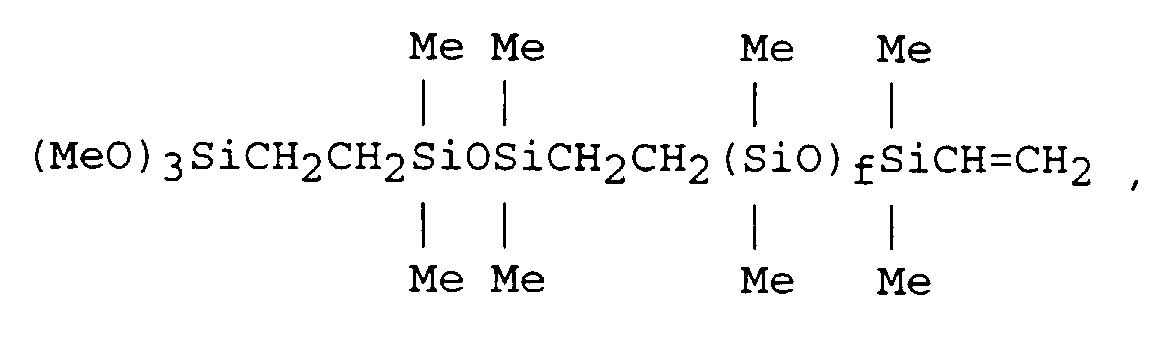
The following ingredients were added at 20-25°C.
and continuously compounded using either an axial
flow mixing turbine or a flow jet mixer. 100 pbw of a
mixture of polydimethylsiloxanes where one type of
polymer is described by the formula
and another type of polymer is described by the formula
where in the polymer mixture 20 percent of the chain
terminations are organosilyl chain terminations and f had
an average value such that the polymer mixture's overall
viscosity was 65 Pas, 5.6 pbw methyltrimethoxysilane, 1.5
pbw diisopropoxy bis(ethyl acetoacetate) titanate, 0.43
pbw tetra-n-butyltitanate, 73 pbw precipitated calcium
carbonate, 0.25 pbw 3-mercaptopropyltrimethoxysilane and
0.2 pbw ethylenediaminepropyltrimethoxysilane were
continuously metered at a total rate of 100 kg/hr into
each mixer and discharged to a drum. Outlet temperature
for sealants compounded in the mixing turbine was 134°C.
and 97°C. for sealants compounded in the flow jet mixer.
For both mixers, process conditions were
selected to achieve optimal filler dispersion. For the
axial flow mixing turbine, the mixer rotational speed was
2000-3000 rpm (linear velocity = 41.7 - 62.5 m/sec.) with
a gap width of 2.5 mm; for the flow jet mixer, the mixer
rotation speed was 900 - 1200 rpm (linear velocity = 25.4
- 33.8 m/sec) with a gap width of 15 mm.
Periodically, samples were collected and
entrained gasses and volatiles were removed by mixing
under vacuum (68kPa to 95kPa) for five to ten minutes in
a small change can mixer. Then 2 mm thick slabs were
cured for 7 days at 20-25°C. and 50±5% relative humidity,
evaluated for appearance and physical properties tested.
Appearance was rated on a numerical scale with ratings
defined as follows:
For the axial flow mixing turbine, compounded
sealant exhibiting appearance ratings ranging from 1 to 2
on the preceding scale were achieved. For the flow jet
mixer, the compounded sealant had appearance ratings of 4
to 5 on the preceding scale. Physical property testing
is provided in Table 3.
| Physical Property Testing |
| Mixer | 100% Modulus (MPa) | Ult. Tensile (MPa) | Ult. Elong. (%) | Durometer (Shore A) |
| Mixing Turbine | 0.67 | 2.4 | 407 | 25 |
| Flow Jet | 0.83 | 2.2 | 337 | 32 |
The following ingredients were added at 20-25°C.
and continuously compounded using either an axial
flow mixing turbine or a flow jet mixer. 100 pbw of a
polydimethylsiloxane (85% hydroxyl endblocked/15%
trimethyl endblocked) with a viscosity of 17 Pas, 5.24
pbw 50/50 weight percent blend of methyltriacetoxysilane
and ethyltriacetoxysilane, 11.7 pbw fumed silica and
0.0263 pbw dibutyltindiacetate were continuously metered
at a total rate of 100 kg/hr into each mixer and
discharged to a drum. Outlet temperature for sealants
compounded in the mixing turbine was 102°C. and 67°C. for
sealants compounded in the flow jet mixer.
For both mixers, process conditions were
selected to achieve optimal filler dispersion. For the
axial flow mixing turbine, the mixer rotational speed was
1000 - 3000 rpm (linear velocity = 20.8 - 62.5
meters/sec.) with a gap width of 2.5 mm; for the flow jet
mixer, the mixer rotation speed was 900 rpm (linear
velocity = 25.4 meters/sec) with a gap width of 15 mm.
Periodically, samples were collected and
entrained gasses and volatiles were removed by mixing
under vacuum (68kPa to 95kPa) for five to ten minutes in
a small change can mixer. Then 2 mm thick slabs were
cured for 7 days at 20-25°C. and 50±5% relative humidity,
evaluated for appearance and physical properties tested.
Appearance was rated on a numerical scale with ratings
defined in Example 3. For the axial flow mixing turbine,
compounded sealant exhibiting appearance ratings ranging
from 2 to 3 on the preceding scale were achieved. For
the flow jet mixer, the compounded sealant had appearance
ratings of 4 on the same scale. Physical property
testing is provided in Table 4.
| Physical Property Testing |
| Mixer | 100% Modulus (Mpa) | Ult. Tensile (MPa) | Ult. Elong. (%) | Durometer (Shore A) |
| Mixing Turbine | 0.56 | 2.1 | 453 | 30 |
| Flow Jet | 0.59 | 2.02 | 406 | 26 |