This non-provisional patent application is based on the following provisional
applications all filed within one year of the filing date of this application.
| U.S. Serial No. | Title | Filing Date |
| 60/110,239 | Low Taper Injection Blow-molded Tumbler | 11/30/98 |
| 60/110,240 | Injection Blow-molded Disposable Tumbler | 11/30/98 |
| 60/110,238 | Large Volume Injection Blow-molded Tumbler | 11/30/98 |
| 60/146,352 | Injection Blow-molded Polycarbonate Containers | 8/2/99 |
| 60/146,354 | Process for Injection Blow-molded Containers | 8/2/99 |
The disclosures of the above applications are hereby incorporated into this application
by reference thereto and the priority of the foregoing applications is claimed in
accordance with 37 CFR 1.78.
The present invention relates generally to disposable tumblers and in
particular to injection blow-molded tumblers of various configurations having a
fortified rim at the upper extremity of the sidewall.
Background
Disposable polymeric articles for packaging, bowls and cups are well known.
Such articles are formed of polystyrene, polypropylene, polyethylene terephthalate
and the like and may be made by thermoforming, injection molding, injection blow-molding,
or other suitable technique. Injection molding has advantages in that a short
cycle time is readily achieved, but tends to be more expensive in terms of material
and articles so formed tend to have anisotropic properties and therefore exhibit
brittleness. Thermoforming likewise tends to have advantageous cycle times,
however, the waste generated tends to be excessive. Moreover, the draw which may
be imposed on the sheet is limited. United States Patent No. 5,693,278 discloses
thermoformed articles produced from polyethylene terephthalate sheet. The
excessive waste problem is addressed in the '278 patent by utilizing at least forty
percent (40%) by weight recycled material.
United States Patent No. 5,433,337 of Willbrandt discloses an injection
molded drink container to fit in vehicle cup holders. The container has an upper rim
20 with a height of from about 1/16 of an inch to about 1/10 of an inch and a width of
from about 0.15 inches to about 0.25 inches. Note Col. 5 at lines 15-25. United States
Patent No. 5,427,269 notes at Col. 5 that this type of container may be produced by
an suitable method, but that injection molding is preferred.
As noted hereinabove, injection molding tends to be expensive in terms of
material, requiring relatively thick-walled parts to compensate for the anisotropy
inherent in the production technique. Disposable containers are preferably made
utilizing as little material as possible.
Many consumers are generally reluctant to use conventional disposable
drinking cups on a frequent basis due to their "look and feel", their expense, or their
performance. Survey data indicate that consumers in many instances prefer
disposable articles whose appearance and performance more closely resemble
glassware. Conventional disposable drinking cups produced by blow-molding
typically rely upon a relatively prominent curled rim to provide rigidity to the article
and accordingly, the article does not resemble glassware to the extent desired.
Moreover, even with the prominent top-curl, conventional blow-molded cups
typically are not rigid enough to mimic glassware. Injection blow-molding processes
and apparatus are widely known and widely used in industry. For example, reference
may be had to U.S. Pat. No. 3,183,552 to Farkas, U.S. Pat. No. 3,819,314 to Marcus,
U.S. Pat. No. 3,339,231 to Piotrowski and Canadian Pat. No. 995,418 to Cannon et
al.
It is known, in general, to use injection blow-molding of polycarbonates to
produce an assortment of containers, see Kirk-Othmer Encyclopedia of Chemical
Technology, Fourth Edition, Vol. 19, p. 600. Further, U.S. Patent No. 4,139,517
discloses reusable milk bottles composed of aromatic polycarbonates and is
specifically directed to a tinted polycarbonate container to prevent milk spoilage
caused by artificial light or sunlight. The patent discloses that the containers can be
prepared by well-known techniques, such as extrusion blow-molding, injection blow-molding,
rotational molding, thermoforming, injection molding and lamination. No
specific processing conditions for the mentioned molding techniques are given.
U.S. Patent Nos. 4,225,304; 4,230,298; 4,234,302 and 4,308,086, issued to
Valyi, disclose a continuous process and apparatus for blow-molding, including
injection blow-molding, containers formed of various plastics including
polycarbonates. Again, no specific process parameters for producing polycarbonate
containers are provided. It is and has been a long standing objective of blow-molding
processes to achieve a high productivity, i.e., to develop a process with a rapid,
efficient and economical operating cycle.
State of the art processes known heretofore are subject to one or more
significant disadvantages. Frequently, they are characterized by a relatively slow
operating cycle. A shorter operating cycle is particularly desirable since it is directly
translatable into a larger number of end products produced. Processes are known
with overlapping cycles in order to reduce overall cycle time, for example, by
providing that while one parison is being molded another is being blown and still
another is being removed. However, even with processes using overlapping cycles
the overall cycle time still leaves much to be desired and still necessitates
improvement in cycle time. The foregoing difficulties are further compounded by
frequent lack of reliability of prior art processes necessitating frequent interruptions
of the operation and thereby further impairing operating efficiency.
U.S. Patent No. 4,540,543 assigned to Canada Cup, Inc., a subsidiary of Fort
James Corporation, discloses an injection blow-molding process and apparatus for
hollow plastic articles. The method and apparatus for injection blow-molding hollow
plastic articles is characterized by a rapid and efficient operating cycle. The injection
mold includes a mold cavity and the blow mold is located adjacent the mold cavity in
a side-by-side relationship. The parison is injection molded into the mold cavity onto
a core. The parison on the core is separated from the mold cavity by moving the
parison on the core axially in a straight path away from the mold cavity, followed by
movement in a substantially arcuate path into axial alignment with the blow mold,
followed by axial movement in a straight path into the blow mold. The advantage of
the method and apparatus of injection blow-molding disclosed in U.S. Patent No.
4,540,543 compared to previous injection blow-molding methods is in its reliability,
preventing interruptions of the injection blow-molding operation and thereby
improving efficiency. The method and apparatus as disclosed in U.S. 4,540,543 have
been used to manufacture thin walled containers from polystyrene. In particular,
disposable containers have been successfully produced from polystyrene. Such
polystyrene containers are desirable because they are reusable and have aesthetic
clarity. However, for producing permanent ware products which have a nominal
thickness typically over 50 mils, it has been found that polystyrene was not
acceptable because of breakage. When producing blow-molded permaware
containers, it is often useful to incorporate onto the base indicia indicating the origin
of manufacture or provide other spatial configurations to the base to aid in subsequent
processing steps such as printing or packaging. However, for relatively thick bases,
the fluid pressure used in blow-molding is not sufficient to adequately press the
parison base against a mold and form an adequately deep molded impression on the
base. Previously, such base molding step was accomplished by removing the
containers from the continuous blow-molding process and stamping the base of the
containers in a wholly separate apparatus. Such separate processing adds significant
energy and time costs to the overall process .
Accordingly, an object of the present invention is to provide a reusable
permanent ware polycarbonate container prepared by injection blow-molding wherein
the container mimics glass but is not as breakable when dropped under normal usage.
Another object of the present invention is to provide a reusable, permanent
ware injection blow-molded polycarbonate container that has good clarity but is more
durable than other plastic containers such as those formed from polystyrene.
A further object of the present invention is to provide a process for injection
blow-molding hollow polycarbonate articles characterized by a rapid, efficient and
economical operating cycle.
A still further object of the present invention is to provide a process as
aforesaid which is convenient and easy to use on a commercial scale and may be
reliably used with high productivity.
Still yet another object of the present invention is to provide a process for
injection blow-molding hollow articles characterized by a rapid, efficient and
economical operating cycle such as provided by U.S. 4,540,543, but use resins other
than polystyrene.
A still further object of this invention is to blow mold hollow permaware
containers and mold the base of such containers in a continuous process without
having to remove the containers from the blow-molding apparatus.
Other objects and advantages of the present invention will become apparent
form the following description and drawings.
Summary of Invention
In a first aspect of the invention there is provided an injection blow-molded
disposable tumbler exhibiting biaxial toughness formed from a polymeric material
comprising: a base forming the bottom of the tumbler defining an outer edge thereof;
a sidewall integrally formed with said base extending upwardly from the outer edge
thereof defining about its upper extremity a fortified rim.
In one preferred embodiment of the present invention there is provided an
injection blow-molded disposable tumbler exhibiting biaxial toughness formed from a
polymeric material including: a base forming the bottom of said tumbler defining an
outer edge thereof; a sidewall integrally formed with the base extending upwardly
from the outer edge thereof having a thickness of from about 5 to about 50 mils
defining about its upper extremity a fortified rim; the sidewall extending upwardly
with a taper of from about 1.0 to about 4.5 degrees; wherein the fortified rim has a
thickness of at least 2 mils greater than the adjacent portion of said sidewall over a
height of at least 2 mils. More typically, the sidewall extends upwardly with a taper
of from about 2.75 to about 4 degrees; and preferably the sidewall extends upwardly
with a taper of about 3 degrees. The fortified rim generally has a thickness and a
height of from about 1.5 to about 6 times the thickness of the adjacent portion of the
sidewall; with from about 3 to about 5 times the thickness of the adjacent portion of
said sidewall being more typical. The tumbler is made from a polymer which is a
thermoplastic optically clear polymer, with a haze value of less than 10, usually
selected from the group consisting of polystyrene, clarified polypropylene, polyesters,
polycarbonates, polyacrylates and styrene acrylonitrile. The volume of said injection
blow-molded tumbler is generally from about 1.5 to about 4 times the volume of an
injection molded parison from which it was prepared; however, a volume of from
about 1.75 to about 3 times the volume of the injection molded parison from which it
was prepared is more typical, while a volume of the tumbler of about twice the
volume of the injection molded parison from which it was prepared is sometimes
preferred. The sidewall has a thickness of from about 10 to about 35 mils, with from
about 15 to about 25 mils being more common. A thickness of about 20 mils is
preferred in many instances. The sidewall may further include a pattern which alters
the cylindrical character thereof over at least a portion of the sidewall which pattern is
operative as a grip portion for a user. A ratio of the height of the tumbler to the inside
diameter of the upper portion of the sidewall is from about 2 to about 4 in some
embodiments, for example, about 3. The tumbler may have a contained volume of
from about 12 to about 15 ounces, or inner volume of about 14 ounces. In some
embodiments, the tumbler has a height of from about 5.75 to about 6 inches.
In another embodiment, there is provided an injection blow-molded
disposable tumbler exhibiting biaxial toughness formed of a polymeric material
including: (a) a base forming the bottom of the tumbler defining an outer edge
thereof; (b) a sidewall integrally formed with the base extending upwardly from the
outer edge thereof having a thickness of from about 5 to about 50 mils defining about
its upper extremity a fortified rim; (c) the sidewall extending upwardly with a taper of
from about 2.5 to about 10 degrees; wherein the fortified rim has a thickness of at
least 2 mils greater than the adjacent portion of the sidewall over a height of at least 2
mils. The sidewall typically extends upwardly with a taper of from about 4.5 to about
10 degrees and preferably the sidewall extends upwardly with a taper of from about
4.5 to about 7.5 degrees. The fortified rim generally has a thickness and a height of
from about 1.5 to about 6 times the thickness of the adjacent portion of the sidewall,
with from about 3 to about 5 times the thickness of the adjacent portion of said
sidewall being more typical. The tumbler is usually formed of optically clear
polymer with a haze value of less than 10 selected from the group consisting of
polystyrene, clarified polypropylene, polyesters, polycarbonates, polyacrylates and
styrene acrylonitrile. The contained volume of the tumbler is generally from about
1.5 to about 4 times the volume of an injection molded parison from which it was
prepared; while from about 1.75 to about 3 times the volume of the injection molded
parison from which it was prepared is more typical. The tumbler is about twice the
volume of the injection molded parison from which it was prepared. The tumbler
sidewall has a thickness of from about 10 to about 35 mils in general, whereas, the
sidewall has a thickness of from about 15 to about 25 mils in most embodiments.
Particularly preferred articles are those wherein the sidewall has a thickness of about
20 mils. The said sidewall may further include a pattern which alters the cylindrical
character thereof over at least a portion of said sidewall which pattern is operative as
a grip portion for a user. The tumbler typically exhibits a ratio of the height of the
tumbler to the inside diameter of the upper portion of the sidewall from about 1 to
about 5; whereas from about 1.3 to about 1.7 is preferred. The height of the tumbler
is from about 4.6 to about 4.8 inches and it has a typical volume of from about 12 to
about 16 ounces; while about 15 fluid ounces is preferred in this embodiment.
In another embodiment, there is provided an injection blow-molded
disposable tumbler exhibiting biaxial toughness formed of a polymeric material
including; a base forming the bottom of the tumbler defining an outer edge thereof; a
sidewall integrally formed with the base extending upwardly from the outer edge
thereof having a thickness of from about 5 to about 50 mils defining about its upper
extremity a fortified rim; the sidewall extending upwardly with a taper of from about
1 to about 10 degrees; wherein the fortified rim has a thickness of at least 2 mils
greater than the adjacent portion of the sidewall over a height of at least 2 mils, said
tumbler defining a volume of at least about 16 fluid ounces. More typically, the
sidewall extends upwardly with a taper of from about 2.75 to about 9 degrees and
preferably with a taper of from about 5 to about 7 degrees. The fortified rim
generally has thickness and a height of from about 1.5 to about 6 times the thickness
of the adjacent portion of the sidewall, while a thickness and height of from about 3
to about 5 times the thickness of the adjacent portion of the sidewall is preferred. The
tumbler is made from a polymeric material which is an optically clear polymer with a
haze value of less than 10, selected from the group consisting of polystyrene, clarified
polypropylene, polyesters, polycarbonates, polyacrylates and styrene acrylonitrile.
The volume of the injection molded tumbler is typically from about 1.5 to about 4
times the volume of an injection molded parison from which it was prepared and the
tumbler defines a volume of from about 16-20 fluid ounces.
The present invention is directed in still yet another embodiment to a reusable,
permanent ware polylycarbonate container and method of making the polycarbonate
container. The polycarbonate container mimics the clarity of glass without having the
undesirable fragile property of glass and is more durable than other plastic containers
such as polystyrene containers. Thus, the polycarbonate containers or tumblers have
the look and feel of glass permaware and can be employed in normal usage without
concern for breakage if the container is dropped. The container or tumbler includes a
base, a sidewall and a fortified upper rim. The sidewall is integrally formed with the
base and extends upwardly from the outer edge thereof. The sidewall is of uniform
caliper or thickness of about greater than 50 thousandths of an inch ("mils") to about
500 thousandths of an inch. The tumbler preferably has a mouth (upper rim) which is
about as wide or wider than the diameter of the remainder of the tumbler. Such
containers are not as easily handled during the blow-molding process as blow-molded
bottles and the like in which the mouth of the bottle is substantially less than the
diameter of the shoulders and remaining portions of the bottle. At the upper
extremity of the sidewall or mouth can be provided a fortified rim which serves to
impart additional rigidity to the container. The fortified rim area has a finite width
and height both of which exceed the thickness of the adjacent sidewall. While the
tumbler is generally cylindrical in overall shape, the tumbler can be provided with
either a uniform or non-uniform taper. The tumbler can be embossed to impart a
decorative pattern on the sidewall. The permaware polycarbonate container of the
present invention is preferably prepared by a side-by-side injection blow-molding
method and apparatus as disclosed in U.S. 4,540,543. The patented method
comprises: providing an injection mold including a mold cavity formed by a mold
wall and a core; injecting molten polycarbonate into the cavity to form a parison on
the core; separating said parison from the mold wall by moving the parison on the
core axially in a straight path away from the mold wall; providing a blow mold
adjacent the mold cavity in side-by-side relationship therewith; moving the parison on
the core in a substantially arcuate path into axial alignment with the blow mold;
moving the parison on the core axially in a straight path into the blow mold; and
expanding the parison on the core in the blow mold at a uniform temperature to form
the hollow container. The apparatus comprises: an injection mold including a mold
wall; a core engageable with said injection mold to form a mold cavity with the mold
wall; means to inject molten polycarbonate into the mold cavity to form a parison
therein; a blow mold adjacent the mold cavity in side-by-side relationship therewith;
means to separate the parison from the mold wall operative to move the parison
axially in a straight path away from the mold wall, followed by in a substantially
arcuate path into axial alignment with the blow mold, followed by axially in a straight
path into the blow mold; and means to expand the parison on the core in the blow
mold to form the hollow container. The core is preferably separated from the hollow
container leaving the container in the blow mold and returned to the injection mold
for another cycle along paths corresponding to the foregoing path, i.e., axially,
substantially arcuate and axially into the injection mold. An ejection station may then
be provided adjacent the blow mold in side-by-side relationship. An ejection core can
transfer the hollow container from blow mold to ejection station and return along
paths corresponding to the paths of the core. In one embodiment, a second core,
second ejection station, second blow mold and second ejection core are provided on
the side opposed to the blow mold and ejection station for operation of an overlapping
cycle. The second core and second ejection core move on paths corresponding to the
paths of the core and ejection core. That is, when the core is in the blow mold the
second core is in the injection mold. A major advantage of the patented blow-molding
process resides in the rapid operating cycle enabled by the critical movement
paths. Also, the process and apparatus are simple, convenient to operate and reliable.
The resultant high productivity is a significant feature. In this aspect of the invention
a method of forming a durable polycarbonate permaware container includes: (a)
injecting molten polycarbonate into a mold cavity formed by a mold wall and a core
to form a polycarbonate parison on the core; separating the parison from the mold
wall by moving the parison on the core axially in a straight path away from the mold
wall; moving the parison on the core in a substantially arcuate path into axial
alignment with a blow mold which is in a side-by-side relationship with the mold
cavity; moving the parison on the core axially in a straight path into the blow mold;
and expanding the parison on the core in the blow mold at a uniform temperature to
form a hollow container having a sidewall integrally formed to a base and a fortified
rim, the sidewall having a uniform thickness of from about greater than 50 mils to
about 500 mils. More typically, the sidewall has a uniform thickness of from about
75 mils to about 375 mils. In most instances, the polycarbonate is injected into the
mold cavity at a temperature of from about 450°F to about 700°F and more typically,
at a temperature of from about 500°F to about 650°F. In general, the molten
polycarbonate is injected into the mold cavity at a pressure of about 1,000 to 3,000
psi and in a preferred embodiment at an injection pressure of about 2,100 psi. The
parison is expanded at a uniform temperature of from about 250°F to about 500°F, at
5 a pressure of from about 100 to about 500 psi. Typically, the polycarbonate
comprises aromatic homopolycarbonate or aromatic copolycarbonate resins with a
melt flow rate of from about 10 to 22 g/10 min. The polycarbonate tumbler is an
injection blow-molded polycarbonate permaware hollow container comprising: a
base forming the bottom of the container defining an outer edge thereof; a sidewall
integrally formed with the base extending upwardly from the outer edge thereof and
having a thickness of from about over 50 to about 500 mils to a fortified rim about its
upper extremity. The fortified rim has a thickness of at least 2 mils greater than an
adjacent portion of the sidewall over a height of at least 2 mils. Both the width and
height of the fortified rim are from about 1.1 to about 4 times a thickness of an
adjacent sidewall. In a particularly preferred article, both the width and the height of
the fortified rim are about 100 mils and the adjacent sidewall is about 80 mils. The
base is from about 1.1 to about 8 times the thickness of the sidewall. The permaware
polycarbonate container is preferably one wherein the bottom of the base has
integrally molded thereto indicia or a configuration different from the remaining base.
) A particularly preferred method of forming a container having a wall thickness
greater than 50 mils comprises: blowing a parison in a blow mold shaped in the form
of said container; inserting within said blown container a core which presses the base
of said container against a mold face having thereon indicia or other structural
configurations so as to mold said indicia or other mold configurations onto the
5 outside surface of the base. Most preferably, the parison is formed from a
polycarbonate plastic and the parison is blown by directing fluid pressure initially at
the top of the parison and directing the fluid pressure from the top toward said base of
said parison.
The present invention is directed in still yet another aspect to improvements in
forming permaware containers by a continuous blow-molding process. The invention
is also directed to improvements in the blow-molding process as disclosed in U.S.
4,540,543 so as to form containers from resins other than polystyrene.
The present invention is characterized in these latter aspects as a side-by-side
injection blow-molding method and apparatus and is at least in part disclosed in U.S.
4,540,543. The patented method comprises: providing an injection mold including a
mold cavity formed by a mold wall and a core; injecting molten resin into the cavity
to form a parison on the core; separating said parison from the mold wall by moving
the parison on the core axially in a straight path away from the mold wall; providing a
blow mold adjacent the mold cavity in side-by-side relationship therewith; moving
the parison on the core in a substantially arcuate path into axial alignment with the
blow mold; moving the parison on the core axially in a straight path into the blow
mold; and expanding the parison on the core in the blow mold at a uniform
temperature to form the hollow container. The apparatus comprises: an injection
mold including a mold wall; a core engageable with said injection mold to form a
mold cavity with the mold wall; means to inject molten resin into the mold cavity to
form a parison therein; a blow mold adjacent the mold cavity in side-by-side
relationship therewith; means to separate the parison from the mold wall operative to
move the parison on the core axially in a straight path away from the mold wall,
followed by in a substantially arcuate path into axial alignment with the blow mold,
followed by axially in a straight path into the blow mold; and means to expand the
parison on the core in the blow mold to form the hollow container. The core is
preferably separated from the hollow container leaving the container in the blow mold
and returned to the injection mold for another cycle along paths corresponding to the
foregoing path, i.e., axially, substantially arcuate and axially into the injection mold.
An ejection station may then be provided adjacent the blow mold in side-by-side
relationship. An ejection core can transfer the hollow container from blow mold to
ejection station and return along paths corresponding to the paths of the core.
In an additional embodiment, a second core, second ejection station, second blow
mold and second ejection core are provided on the side opposed to the blow mold and
ejection station for operation of an overlapping cycle. The second core and second
ejection core move on paths corresponding to the paths of the core and ejection core.
That is, when the core is in the blow mold the second core is in the injection mold.
Obviously, additional cores, ejection stations, blow molds, and ejection cores can be
provided and operated in an overlapping cycle to increase productivity. A major
advantage of the patented blow-molding process resides in the rapid operating cycle
enabled by the critical movement paths. Also, the process and apparatus are simple,
convenient to operate and reliable. The resultant high productivity is a significant
feature.
In accordance with this invention, the above patented process is used to form
injection blow-molded containers formed of polymers other than polystyrene. Thus,
it has been found that the above patented process can be used to form clear containers
from resins such as polycarbonate, polyethylene terephthalate, polycarbonate/ABS
mixed resin, acrylic resins, clarified (amorphous) polypropylene and
polyvinylchloride. Additionally, the present invention is directed to a process of
molding the base of a blown container without removing the container from the blow
mold. In this invention, after the parison is blown to the container in the blow cavity,
an ejection core is inserted into the container while the container remains in the blow
cavity. The ejection core pushes the base of the container against a mold opposed to
the outside surface of the container base. The mechanical pressure of the ejection
core against the container base is sufficient to adequately transfer the molded
configuration of the mold onto the outside surface of the container base. Once the
base is molded, the container can be removed from the blow cavity by the ejection
core on a continuous basis. The continuous process saves considerable time and
energy over prior art processes which required a stamping step after the container had
been removed from the blow cavity. There is thus provided a method of forming a
container comprising: injecting molten resin into a mold cavity formed by a mold
wall and a core to form a resinous parison on the core; separating the parison from the
mold wall by moving the parison on the core axially in a straight path away from the
mold wall; moving the parison on the core in a substantially arcuate path into axial
alignment with a blow mold which is in a side-by-side relationship with the mold
cavity; moving the parison on the core axially in a straight path into the blow mold;
and expanding the parison on the core in the blow mold at a uniform temperature to
form a hollow container; wherein the resin is selected from the group consisting of
filled polystyrene, filled and non-filled polycarbonate, polyethylene terephthalate,
polycarbonate and ABS mixtures, acrylic resins, clarified polypropylene and
polyvinylchlroide. The filled resins contain up to 5 wt.% of nanometer-sized particles
which may comprise a clay. In one embodiment, a transparent drinking tumbler is
comprised of polystyrene filled with nanometer-sized particles having a size within
the range of visible-light wavelengths. In another aspect, there is provided a method
of forming a container having a wall thickness greater than 50 mils, the container
containing sidewalls and an integrally formed base, the method comprising: blowing
a parison in a blow mold shaped in the form of the container to form a hollow
container, inserting within the hollow container, which remains in the blow mold, a
core which presses the base of the container against a mold face having thereon
indicia or other structural configurations so as to mold the indicia or other mold
configurations onto the outside surface of the base. Another method involves
forming a container comprising: (a) injecting molten resin into a mold cavity formed
by a mold wall and a core to form a resinous parison on the core; (b) separating the
parison from the mold wall by moving the parison on the core axially in a straight
path away from the mold wall; (c) moving the parison on the core in a substantially
arcuate path into axial alignment with a blow mold which is in a side-by-side
relationship with the mold cavity; (d) moving the parison on the core axially in a
straight path into the blow mold; and (e) expanding the parison on the core in the
blow mold by directing fluid initially at the top of the parison and directing the fluid
pressure from the top toward the base of the parison at a uniform temperature to form
a hollow container; there the resin is selected from the group consisting of
polycarbonate, polyethylene terephthalate, polycarbonate and ABS mixtures, acrylic
resins, clarified polypropylene and polyvinylchloride.
In still further embodiments of the present invention, there is provided an
injection blow-molded tumbler with a fortified rim having a thickness greater than the
adjacent sidewall formed of a polymeric material including a styrene/butadiene
copolymer. In general, the copolymer is from about 2 to about 40 percent by weight
butadiene residue with from about 8 to about 15 percent by weight butadiene residue
in the composition being typical. The tumbler may consist entirely of
butadiene/styrene copolymer, or the copolymer may be blended with other polymers,
for example, polystyrene.
Alternatively, polystyrene or other polymeric composition may be provided
with an impact modifier. Typically, impact modifiers may be core-shell polymers,
olefin containing copolymers, rubber polymers, rubber copolymers, styrene
containing copolymers and mixtures thereof. So also, the inventive tumblers may be
made from filled polymeric compositions including conventional filler such as mica,
talc and the like. Suitable filled compositions may include from 5 to 50 weight
percent filler, with from about 8 to about 20 percent filler being more typical. From
about 10 to about 15 weight percent filler is perhaps most suitable for the injection
blow-molded tumblers.
Brief Description of Drawings
The invention is described in detail below with reference to numerous
examples and drawings. In the drawings:
Detailed Description
The invention is described below in connection with various embodiments and
aspects. Modifications to particular embodiments within the spirit and scope of the
present invention, which is set forth in the appended claims, will be apparent to those
of skill in the art.
Disposable tumblers in accordance with the present invention more closely
resemble conventional glassware and mimic its rigidity, performance and "look and
feel" than do previously known blow-molded articles. Salient features include the
biaxial-induced toughness of the blow-molded article, as well as rigidity achieved by
combing a relatively low taper with a fortified upper rim. Conventional blow-molded
cups typically include a very prominent curled lip which is not consistent with
glassware and tends to make the article unappealing for everyday use or for use with
guests.
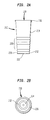
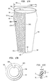
There is shown in Figures 1(a) through 1(c) a tumbler 10 constructed in
accordance with the present invention. In general, tumbler 10 has a base portion 12, a
sidewall portion 14 and an upper circular rim portion 16 which extends about the
periphery 18 of an opening 20 of tumbler 10. Base portion 12 of tumbler 10 is
integrally formed with the rest of the tumbler and includes a bottom 22 which has a
meniscus portion 24 and a base sidewall 26. Base sidewall 26 is typically thicker
than sidewall 14, and has substantially zero taper.
Tumbler 10 is optionally provided with a molded-in design 28 which is more
clearly seen by reference to Figures 1(b) and 1(c). Base sidewall 26 extends
upwardly to define an outer edge 30 which attaches to sidewall 14. Sidewall 14
extends upwardly to fortified rim 16. Rim 16 is integrally formed with sidewall 14
and is a continuous generally circular or oval, solid polymer bead extending about
periphery 18 of opening 20. Rim 16 has a width 31 which is defined by the
difference between an inner diameter 32 and an outer diameter 34 of rim 16 and a
height 35 which is the distance over which width 31 extends. Width 31 is thicker than
adjacent sidewall portion 38 which is typically of the same caliper as the reset of
sidewall 14. In the example shown in Figures 1(a) - 1(c), adjacent sidewall portion
38 has a thickness of 10 mils, height 35 is approximately 28 mils and width 31 is
approximately 40 mils at its thickest point.
Other dimensions of tumbler 10 are indicated on Figure 1(a). Base portion 12
has a diameter D, at edge 30 of about 2.125 inches, an outer upper diameter 34 of
2.770 inches an inner upper diameter 32 of 2.730 inches. The overall height, H, of
tumbler 10 is 5.785 inches. These dimensions define an angle of taper T as shown
about imaginary central axis 40 of about 3° for sidewall 14 of tumbler 10. As used
herein "taper", "degree of taper" and like terminology indicates the angle that the
sidewall of the inventive tumbler makes with the imaginary central longitudinal axis
defined by the sidewall which is substantially perpendicular to bottom 22, the taper of
the article may also be thought of as the angle the sidewall makes with the bottom
less 90 degrees.
Figure 1(c) shows a molded in swirl design 28 which extends from base
portion 12 to roughly 50 per cent of the height of tumbler 10. Design 28 is comprised
of wall embossments at least as prominent as ½ the caliper of sidewall 14 and
typically of the same thickness or prominence of the sidewall. Thus, design 28
substantially alters the topography of sidewall 14 and provides a secure grip for a
user, as well as a modicum of longitudinal reinforcement.
There is shown in Figures 2(a) and 2(b) another tumbler 210 constructed in
accordance with the present invention. In general, tumbler 210 has a base portion
212, a sidewall portion 214 and an upper circular fortified rim portion 216 which
extends about the periphery 218 of an opening 220 of tumbler 210. Base portion 212
of tumbler 210 is integrally formed with the rest of the tumbler and includes a bottom
222 which has a meniscus portion 224 and a base sidewall 226. Base sidewall 226 is
typically thicker than sidewall 214, and has slightly reversed taper as opposed to the
taper of sidewall 214.
Tumbler 210 is provided with a molded-in design 228 which is a series of
concentric rings as shown on Figures 2(a) and 2(b). The dimensions of tumbler 210
are otherwise substantially identical to the dimensions of the tumbler 10 of Figures
1(a) - 1(c).
There is shown in Figures 3(a) through 3(d) a tumbler 310 constructed in
accordance with the present invention. In general, tumbler 310 has a base portion
312, a sidewall portion 314 and an upper circular fortified rim portion 316 which
extends about the periphery 318 of an opening 320 of tumbler 310. Base portion 312
of tumbler 310 is integrally formed with the rest of the tumbler and includes a bottom 322 which has a meniscus portion 324 and a base sidewall 326. Base sidewall 326 is
thicker than sidewall 314 and has a slight taper.
Tumbler 310 is optionally provided with a "cut-glass" molded-in design 328
which is most clearly seen by reference to Figures 3(b) and 3(c). The molded in
design defines a series of triangular ridges which are deeper in dimension than the
wall caliper of sidewall 314, thus providing strength by way of corrugation. The
molded in cut glass grooves 328 have a wall thickness the same as the rest of the
tumbler and a depth of up to about 1/8 inch as shown.
Base sidewall 326 extends upwardly to define an outer edge 330 which
attaches to sidewall 314. Sidewall 314 extends upwardly to fortified rim 316.
Rim 316 is integrally formed with sidewall 314 and is a continuous generally circular
or oval, solid polymer bead extending about periphery 318 of opening 320. Rim 316
has a width 331 which is defined by the difference between an inner diameter 332 and
an outer diameter 334 of rim 316 and a height 335 which is the longitudinal distance
over which width 331 extends. Width 331 is thicker than adjacent sidewall portion
338 which is typically of the same caliper as the rest of sidewall 314. In the example
shown, adjacent sidewall portion 338 has a thickness of 20 mils height 335 is
approximately 28 mils and width 331 is approximately 40 mils at its thickest point.
Other dimensions of tumbler 310 are approximately identical to those of tumblers 210
of Figures 2(a) and 2(b) and tumbler 10 of Figures 1(a) - 1(c). Tumbler 310 thus
has a taper of 3°.
Tumbler 310 is particularly rigid due to the triangular ridge "cut glass" pattern
328 which extends upwardly from the base over about 40% of the height of the glass,
forming a grip for the user, as can best be appreciated from Figure 3(b). As can be
seen from Figure 3(b), the ridges are accordion shape when viewed in section,
wherein segments have flat surfaces 344 having a width of one quarter of an inch or
so. As shown in Figures 3(c) and 3(d), there is an angle, S, between connected
segments of 130 degrees and each triangular segment extends over an angle S1 of
about 15 degrees of the periphery of the tumbler.
Referring to Figure 4(a), there is schematically depicted a lip curl
characteristic of prior art disposable drinking cups. In general, such prior art cups
have a sidewall 414a of a given thickness D4a which extends upwardly into a curl
generally indicated at 450a. The curl has a characteristic radius Ra as well as a height
Ha and a width Wa. Such structures are sometimes called "open top curls" and may
be seen, for example, in United States Patent No. 4,540,543. See Figure 4 thereof at
31.
Figure 4(b) schematically depicts in section and elevation a solid polymer
bead about the upper periphery of a tumbler, that is, an embodiment of the fortified
rim of the present invention which extends around the upper periphery of the
inventive tumbler. The tumbler has a sidewall 414b of thickness D4b. The fortified
rim, 416b is formed of solid polymer integrally formed with sidewall 414b and has a
height Hb and width Wb as indicated. Inasmuch as the cross section of the
embodiment shown in circular, the width Wa is approximately equal to the height
Wb.
Bead 416b has advantages over the prior art top curl, whether or not one is
seeking to mimic glassware. For one, it rounded and will not tend to snag on the mold
or snag with a cup cover as to prior art top-curls. For another advantage, a bead type
top rim can more compactly provide rigidity to a cup than does a top curl, with less
width. While polymer bead 416b is shown as circular in cross section, other profiles
may be suitable for example, conic sections such as ellipsoid shapes of truncated
conic sections or profiles such as truncated conic section including a semi-circle or a
half ellipse.
As noted above, tumblers in accordance with the present invention are
produced by injection blow-molding. Optically opaque materials may be used,
however, optically transparent polymers are usually preferred. Particularly preferred
polymers include crystal polystyrene available from Dow Corporation, Midland,
Michigan, grade 685d. this polymer may be used to produce the inventive tumblers
by the method of United States Patent No.4,540,543, the disclosure of which is
incorporated herein by reference. The subject apparatus and method is generally
shown and described in connection with Figure 5.
There is illustrated in Figure 5 an injection mold 555, a blow mold 557 and an
ejection station 559. Together with core 561, mold 555 defines an injection mold
cavity wherein a parison 563 is injection molded. Core 561, mold 555 are provided
with passageways 565 to apply fluid pressure to aid processing of the tumbler noted
in the '543 patent. After injection molding, parison 563 is retained on core 40 and
moved to blow mold 557. Parison 563 is of predetermined volume and has at its
upper periphery a fortified rim 516 in accordance with the invention. The parison is
expanded to the desired shape in blow mold 557 to a volume of from about 1.5 to
about 4 times its former volume on core 561. This process imparts biaxial orientation
to the article, reducing the anisotropy inherent in the injection molding process and
proving biaxial toughness to the article.
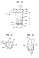
There is shown in Figures 6(a) through 6(c) a tumbler 610 constructed in
accordance with the present invention. In general, tumbler 610 has a base portion
612, a sidewall portion 614 and an upper circular rim portion 16 which extends about
the periphery 618 of an opening 620 of tumbler 610. Base portion 612 of tumbler
610 is integrally formed with the rest of the tumbler and includes a bottom 622 which
has a meniscus portion 624 and a base sidewall 626. Base sidewall 626 is typically
thicker than sidewall 614, and has either no taper, or a reverse taper from the taper of
sidewall 614.
Tumbler 610 is optionally provided with a molded-in design 628 which is
more clearly seen by reference to Figures 6(b) and 6(c). Molded in designs may
define ridges which are deeper in dimension than the wall caliper of sidewall 614,
thus providing strength by way of corrugation, much like as is known in connection
with cardboard. The design shown is an alternating saw-tooth type, slightly curved,
with larger curves alternating with smaller curves about the entire periphery of the
tumbler. The design is also operative as a grip for a user since the smooth sidewall is
substantially altered.
Base sidewall 626 extends upwardly to define an outer edge 630 which
attached to sidewall 614. Sidewall 614 extends upwardly to fortified rim 616.
Rim 616 is integrally formed with sidewall 614 and is a continuous generally circular
or oval, solid polymer bead extending about periphery 618 of opening 620. Rim 616
has a width 631 which is defined by the difference between an inner diameter 632 and
an outer diameter 634 of rim 616 and a height 635 which is the distance over which
width 631 extends. Width 31 is thicker than adjacent sidewall portion 638 which is
typically of the same caliper as the rest of sidewall 614, that is, sidewall 614 is
substantially uniform in thickness on the entire tumbler. In the example shown,
adjacent sidewall portion 638 has a thickness of 20 mils, height 635 is approximately
28 mils and width 631 of rim 616 is approximately 40 mils at its thickest point.
The other dimensions of tumbler 610 are indicated on Figures 6(a) through
6(c). Base portion 612 has a diameter, dl, at edge 630 of about 2.125 inches, an outer
upper diameter 34 of 3.32 inches and an inner upper diameter 632 of 3.279 inches.
The overall height, H of tumbler 10 is 4.75 inches. These dimensions, as can be seen
from Figure 6(c), define an angle of taper T as shown about imaginary central axis
40 of about 7° for sidewall 614 of tumbler 610. As used herein, "taper", "degree of
taper", or like terminology indicates the angle that the sidewall of the inventive
tumbler makes with the imaginary central longitudinal axis defined by the sidewall
which is substantially cylindrical or conical depending upon the embodiment.
Inasmuch as the sidewall is substantially perpendicular to bottom 622, the taper may
also be thought of as of the angle the sidewall makes with the bottom less 90 degrees.
Figure 6(c) shows a molded in "sawtooth" swirl design 628 which extends
from base portion 612 to roughly 65 per cent of the height of tumbler 610. Design
628 is comprised of wall embossments at least as prominent as ½ the caliper of
sidewall 614. Typically the molded in ridges of the design are about as deep as the
wall caliper. Thus, design 628 substantially alters the topography of sidewall 614 and
provides a secure grip for a user.
There is shown in Figures 7(a) through 7(c) another tumbler 710
constructed in accordance with the present invention. Tumbler 710 has a base portion
712, a sidewall portion 714 and an upper circular rim portion 716 which extends
about the periphery 718 of an opening 720 of tumbler 710. Base portion 712 of
tumbler 710 is integrally formed with the rest of the tumbler and includes a bottom
722 which has a meniscus portion 724 and a base sidewall 726. Base sidewall 726 is
typically thicker than sidewall 714, and has a reverse taper from the taper of sidewall
714, as can be seen from Figure 7(a).
Tumbler 710 is optionally provided with a fluted molded-in design 728
which is seen by reference to Figure 7(b). Each flute 719 is substantially a flat,
rectangular shape and approximately 30 degrees about the periphery 242 of the glass.
Molded-in design 728 provides strength as is known in connection with injection
molded drinking vessels. Base sidewall 726 extends upwardly to define an outer edge
730 which attaches to sidewall 714. Sidewall 714 extends upwardly to fortified rim
716.
Rim 716 is integrally formed with sidewall 714 and is a continuous
generally circular or oval, solid polymer bead extending about periphery 718 of
opening 720. Rim 716 has a width 731 which is defined by the difference between
an inner diameter 732 and an outer diameter 734 of rim 716 and a height 735 which is
the distance over which width 731 extends. Width 731 is thicker than adjacent
sidewall portion 738 which is typically of the same caliper as the rest of sidewall 714.
In the example shown, adjacent sidewall portion 738 has a thickness of 20 mils,
height 736 is approximately 28 mils and width 731 is approximately 40 mils at its
thickest point.
Other dimensions of tumbler 710 are generally as indicated in connection
with tumbler 610 of Figure 6. Sidewall 714 of tumbler 710 has a taper of
approximately 6.5 degrees.
The tumblers of Figures 6 and 7 have the fortified rim design of the present
invention wherein the rim includes a spherical or elliptical solid polymer bead.
Typically, this bead is twice the thickness of the adjacent sidewall or more as was
discussed in connection with Figures 4(a) and 4(b) above. That discussion applies
equally to the embodiments of Figures 6, 7, 8 and 17 as will be appreciated from the
foregoing and subsequent discussion.
Salient features of the inventive tumblers include the biaxial-induced
toughness of the blow-molded article, as well as rigidity achieved by combining a
relatively low taper with a fortified upper rim. Conventional blow-molded cups
typically include a very prominent curled lip which is not consistent with glassware
and tends to make the article unappealing for everyday use or for use with guests.
Moreover, the rim is larger than a comparable rim on tumblers of the invention such
that there is more rim stress upon flexing, especially in connection with larger volume
tumblers as will be appreciated from the following.
There is shown in Figure 8 a tumbler 810 which is constructed in accordance
with the present invention. In general, tumbler 810 is cylindrical or in the shape of a
truncated cone and has a base portion 812, a sidewall portion 814 and an upper
circular rim portion 816 which extends about the periphery 818 of an opening 820 of
tumbler 810. Base portion 812 of tumbler 810 is integrally formed with the rest of the
tumbler and includes a bottom 822 which has a meniscus portion 824 and a base
sidewall 826. Base sidewall 826 is typically thicker than sidewall 814, and has either
no taper, or reverse taper from the taper of sidewall 814.
Base sidewall 826 extends upwardly to define an outer edge 830 which
attaches to sidewall 814. Sidewall 814 extends upwardly to fortified rim 816. Rim
816 is integrally formed with sidewall 814 and is a continuous generally circular or
oval, solid polymer bead extending about periphery 818 of opening 820. Rim 816 has
a width 831 which is defined by the difference between an inner diameter 832 and an
outer diameter 834 of rim 816 and a height 835 which is the distance over which
width 831 extends. Width 831 is thicker than adjacent sidewall portion 838 which is
typically of the same caliper as the rest of sidewall 814, that is, sidewall 814 is
substantially uniform in thickness on the entire tumbler. In the example shown,
adjacent sidewall portion 838 has a thickness of 20 mils, height 835 is approximately
28 mils and width 831 of rim 816 is approximately 28 mils and width 831 of rim 816
is approximately 40 mils at its thickest point. The tumbler is also provided with a
series of molded-in grooves 841 which extend around the tumbler. These grooves
provide a grip for a user as well as providing rigidity to the article. Typically, the
circumferential grooves 841 have a depth of from 810 to 40 mils.
Other dimensions of tumbler 810 are indicated on Figure 8 and Table I in
connection with the tumbler of Figure 8(b) as shown schematically in Figure 4(b).
Base portion 812 has a diameter dl, at edge 830 of about 2.5 inches, an outer upper
diameter 834 of 3.38 inches and an inner upper diameter 832 of 3.32 inches. The
overall height, H of tumbler 810 is about 4.6 inches. These dimensions define an
angle of taper T as shown about imaginary axis 840 of about 5° for sidewall 814 of
tumbler 810. As used herein, "taper", "degree of taper" or like terminology indicates
the angle that the sidewall of the inventive tumbler makes with the longitudinal axis
defined by the sidewall which is substantially cylindrical or conical depending upon
the embodiment. Inasmuch as the sidewall is substantially perpendicular to bottom
822, the taper may also be though of as of the angle the sidewall makes with the
bottom less 90 degrees, because the axis of the tumbler is substantially perpendicular
to bottom 822 as shown.
Referring again to
Figure 4(a), there is schematically depicted a lip curl
characteristic of prior art disposable drinking cups. In general, such prior art cups
have a
sidewall 414a with a portion
438a adjacent the curl of a given thickness
D2a
which extends upwardly into a curl generally indicated at
450a. The curl has a
characteristic radius
Ra as well as a height
Ha and a width
Wa. Such structures are
sometimes called "open top curls" and may be seen, for example, in United States
Patent No. 4,540,543.
See Figure 4 thereof at
31. Figure 4(b) schematically depicts
in section and elevation a solid polymer bead
416 about the upper periphery of a
tumbler, that is, an embodiment of the fortified rim of the present invention as is also
shown in
Figure 8 hereof which extends around the upper periphery of the inventive
tumbler. The tumbler has a
sidewall 414b with a portion
adjacent rim 416b of
thickness
D2b. the fortified rim,
416b is formed of solid polymer integrally formed
with
sidewall 414b and has a height
Hb and width
Wb as indicated. Inasmuch as the
cross section of the embodiment shown is circular, the width
Wa is approximately
equal to the height
Hb. Bead
416b has advantages over the prior art top curl. For
one, it is rounded and will not tend to snag on the mold or snag with a cup cover as do
prior art top-curls. For another advantage, a bead type top rim can more compactly
provide rigidity to a cup than does a top curl, with less width as demonstrated below
in Table I, even for a relatively large volume container such as that shown in
Figure
8.
| Impact of Dimensions Upon Rigidity |
| Container | Cup of Figure 4(a) | Tumbler of Figure 4(b) and Figure 8 |
| | Open Rim | Solid Rim |
| Sidewall Caliper, Inches | 0.0150 | 0.0150 |
| Top Curl Caliper, Inches | 0.0150 | 0.0628 |
| Top Curl/Sidewall Caliper Ratio | 1.00 | 4.19 |
| Top Curl Width, Inches | 0.084 | 0.063 |
| Taper, Degrees | 5.0 | 5.0 |
| Inside height, Inches | 4.584 | 4.584 |
| Upper Inside diameter, Inches | 3.3250 | 3.3250 |
| Lower Inside diameter, Inches | 2.5200 | 2.5200 |
| Volume, Ounces | 17.1448 | 17.1448 |
| Rigidity, LBS/0.25" Deflection | 1.045 | 1.045 |
Being more compact, less hoop stress about the rim is generated upon flexing
of the cup. While polymer bead 416b is shown as circular in cross-section, other
profiles may be suitable for example, conic sections such as ellipsoid shapes or
truncated conic sections or profiles such as truncated conic section including a semi-circle
or a half ellipse. As noted above, tumblers in accordance with the present
invention are produced by injection blow-molding optically transparent polymers.
Particularly preferred polymers include crystal polystyrene available from Dow
Corporation, Midland, Michigan, with the grade designation 685D. This polymer
may be used to produce the inventive tumblers by the method of United States Patent
No. 4,540,543, the disclosure of which is incorporated herein by reference. The
subject apparatus and method is shown and described in more detail in connection
with the embodiments of the present invention which follow.
The present invention is directed in still yet further embodiments to a reusable
polycarbonate container or tumbler and method of making the polycarbonate
container. The reusable or permaware polycarbonate container of the present
invention is made by an injection blow-molding process to provide a polycarbonate
container which mimics the aesthetic clarity of glass and polystyrene containers but is
more durable than either glass or polystyrene containers of comparable caliper and
shape. The permaware polycarbonate containers or tumblers include a base, a
sidewall and a fortified upper rim. The sidewall is integrally formed with the base
and extends upwardly from the outer edge thereof. The sidewall is of uniform caliper
or thickness of greater than about 50 thousandths of an inch ("mils") to about 500
thousandths of an inch. Preferably, the caliper of the sidewall ranges from about 75
mils to about 375 mils. While the tumbler in accordance with the invention is
generally cylindrical in overall shape, the sidewall preferably has either a uniform or
non-uniform taper from an imaginary central axis from the base to the opening. The
height of the tumbler is from about 5 to 10 inches. At the upper extremity of the
sidewall is a fortified rim which serves to impart rigidity to the tumbler. The fortified
rim area has a finite width and height both of which exceed the thickness of the
adjacent sidewall. The rim is at least 2 mils thicker than the adjacent sidewall over a
height of at least 2 mils; preferably, both the width and the height of the rim are from
about 1.1 to about 4 times the thickness of the adjacent sidewall. The base ranges
from about 1.1 to about 8 times, preferably, from about 1.1 to about 4 times the
thickness of the sidewall. Generally speaking, the tumbler in accordance with the
invention, has a volume of at least 1.5 and up to 4 times the volume of the injection
molded parison from which it was prepared; while volume ratios (sometimes referred
to as "blow ratio") of from about 1.75 to about 3 are typical. A blow ratio of about 2
to about 2.5 is most preferable. Articles in accordance with the present invention are
distinguished from other containers, such as bowls or other flat shapes where rigidity
is not critical, by virtue of the fact that the ratio of the height of the tumbler to the
diameter of the upper opening is generally in the range of from about 1 to about 5.
Ratios of 1.25 to about 4 are preferred, while ratios of about 1.5 to about 3.5 are more
preferred.
An example of a polycarbonate container in accordance with the present
invention is a "bell fountain" container illustrated in Figures 17(a) - (c) and is
described in detail below. The reusable polycarbonate containers are preferably
prepared by the rapidly and economically efficient side-by-side injection blow-molding
process as disclosed in aforementioned U.S. 4,540,543. The process is
described below in combination with the drawings of Figures 9-19. U.S. 4,540,543
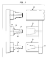
is herein incorporated by reference in its entirety. Referring to Figures 9-11,
injection station 910 is secured in fixed platen 911. Blow stations 912 and 913 are
also secured to fixed platen 911 and are situated adjacent injection station 910 and in
side-by-side relationship with respect thereto, with blow station 912 containing blow
mold 916 which may be split if desired being on one side of the injection station and
blow station 913 containing blow mold 917 which may be split if desired being on the
other side. Blow molds 916 and 917 are in the shape of the hollow articles to be
made. Ejection stations 914 and 915 are also secured to fixed platen 911 and are
situated adjacent the respective blow stations in side-by-side relationship with respect
thereto, with ejection station 914 situated adjacent blow station 913 and ejection
station 915 situated adjacent blow station 912.Core 920 is provided secured to
movable platen 921 engageable with injection station 910 as shown in Figure 9. The
injection station 910 includes mold wall 922. Thus, when core 920 is engaged with
injection station 910 as shown in Figure 9 the core 920 is spaced from the mold wall 922 to form mold cavity 923 therebetween. Injection means 924 is in communication
with mold cavity 923 and is connected to a source of hot flowable plastic, i.e.,
polycarbonate, (not shown) for forcing said hot formable plastic under pressure into
mold cavity 923 to form parison 925. Core 920 is movable into and out of
engagement with injection station 910 by movable platen 921 actuated by the motive
means shown schematically in Figure 9 and to be described in more detail herein
below. Naturally, the movement of platen 921 may be accomplished by conventional
means, shown only schematically in Figure 9, which are capable of providing a
clamping force between the two platens to keep them from separating during the
injection step and the other steps which will be described below. It should be
understood that while movement of platen 921 is described, one may of course move
platen 911 or both platens 911 and 921, if desired. The hot, newly formed parison or
container 925 remains in mold cavity 923 until sufficiently cooled to be removed, if
desired using cooling means 926 adjacent mold wall 922, as for example, by fluid
circulation. If desired, such cooling means may also be provided in core 920. After
such cooling of parison 925, the clamping force is released and platen 21 is moved
away from platen 11 carrying with it core 920 and parison 925 adhered thereto. If a
neck mold is used as to form a threaded neck portion the neck mold is operable by
conventional means and remains closed during the formation of the parison, removal
of the parison from the injection station and blowing, which also aids in retention of
the parison on the core. In the present embodiment, a neck mold is not employed and
both the parison and final article have a cup-shaped configuration as seen in the
drawings and clearly shown in Figure 13 and Figure 17. In such configuration, the
top or mouth of the container (mold) is about as wide or wider than the diameter of
the remainder of the container mold. Thus, parison 925 has a base portion 930, a
fortified rim or lip 931 and outwardly flaring side walls 932 extending from base 930
to lip 931. Fortified rim 931 may serve as an undercut to aid in retention of the
parison on the core. Core 920 is provided with fluid passageway 933 connected to a
source of fluid pressure for blowing the final article. If desired, a vacuum may be
drawn through passageway 933 to aid in retention of the parison on the core. Core
920 with parison 925 thereon is then moved to blow station 913 as shown in Figures
10 and 11 in a manner which first separates the parison from the mold wall 922 by
moving parison core 920 axially in a straight path away from said mold wall at least
until the parison clears the injection station, followed by movement in a substantially
arcuate path into axial alignment with blow station 913 and blow mold 917, followed
by moving the parison core axially in a straight path into blow mold 917. Parison 925
is then expanded on core 920 in blow mold 917 by fluid pressure through passageway
933 to form hollow article 934. Figure 9 shows core 920 engaged with the injection
station. Figure 10 shows core 920 with parison 925 thereon removed from the
injection station on its arcuate path between injection station 910 and blow station
913 with platen 921 and core 920 at the peak of their arcuate path. Figure 10 shows
core 920 engaged with blow station 913 forming hollow article 935 therein. After the
formation of hollow article 934, core 920 is removed from blow station 913 leaving
hollow article 934 remaining therein and returned to the injection station along paths
corresponding to the path taken by core 920 from the injection station 910 to the blow
mold 917, that is, the core is moved axially in a straight path away from blow mold
917 followed by movement in a substantially arcuate path into axial alignment with
said injection station, followed by movement axially in a straight path into said
injection station for repeat of the cycle.
Second core 940 having fluid passageway 945 similar to passageway 933 is
provided on movable platen 921 adjacent core 920 in side-by-side relationship with
respect thereto. Second core 940 is engageable with injection station 910 when core
920 engages blow mold 917 to form a second parison in an overlapping cycle with
respect to core 920. Thus, second core 940 engages injection station 910 to form a
parison 925 in a manner similar to the formation of a parison on core 920 in the
injection station 910. The formation of a parison on core 940 takes place while core
920 is in the blow mold 917 forming the hollow article. Core 940 carrying a parison
925 is then removed from the injection station and transferred to blow station 912 and
blow mold 916 in a path corresponding to the transfer path of core 910 to blow station
913 and blow mold 917 for formation of additional hollow article 934 in blow mold
917. The transfer of core 940 to blow mold 917 takes place simultaneously with the
return of core 920 to injection station 910. After removal of core 920 from blow
station 913 hollow article 934 remains in blow mold 917. Hollow article 934
corresponds in shape generally to parison 925 with an expanded configuration caused
by the blowing step. Thus, article 934 has a base portion 941, fortified rims or lips
942 and outwardly flaring side walls 943 extending from base 941 to lips 942. The
blown article 934 cools in contact with the walls of the blow mold which may contain
cooling means 944, as for example for cooling by fluid circulation in a conventional
manner. Article 934 may be retained in the blow mold by any desired means as by
applying a vacuum to the inside of the blow mold or providing means on the blow
mold to engage lip 942.
Ejection core 950 and second ejection core 951 are provided on movable
platen 921 adjacent and in side-by-side relationship to cores 940 and 920, with
ejection core 951 alongside second core 940. Thus, when cores 920 and 940 leave
their respective blow molds 917 and 916 with the hollow articles remaining therein
for return to the injection station, ejection cores 950 and 951 move into engagement
with said hollow articles in the blow molds along paths corresponding to the paths of
cores 920 and 940. Cores 950 and 951 then disengage from the blow molds removing
hollow articles 934 with them and move from the blow stations to the ejection
stations along paths corresponding to the paths of cores 920 and 940. Removal of
hollow article 934 onto the ejection cores may be assisted by pusher means 952
operatively associated with blow molds 916 and 917 for positively pushing article
934 away from the blow molds, see Figures 12 and 13. Also, ejection cores 950 and
951 may be provided with fluid passageways 953 connected to a source of fluid
pressure (not shown), see Figure 13, which may be used to draw a vacuum and aid in
removal of hollow article 934 from the respective blow molds. The final hollow
article is then transferred to the respective ejection station, which may incorporate
any suitable ejection means as the chute, suction tube or other conventional means to
convey plastic articles. Removal of article 934 from the ejection cores 950 and 951 at
ejection stations 914 and 915 may be assisted by flow pressure from passageway 953
and also by stripper 954 including stem 955 to which a widened cap 956 is attached
(Figures 12 and 13) movable axially via motive means (not shown). After removal
of the hollow article 934 at the ejection stations the cycle is repeated. The apparatus,
particularly for use with cup-shaped articles, assures holding of the articles
concentrically on the mandrels and effecting reliable transfer as shown in Figure 13.
In operation, the parison is transferred into blow mold 917 as above described
and blown into final shape therein, followed by insertion of mandrel 950 which is
shorter than the depth of the blow mold. In order to remove the blown article 934,
pusher plate 952 is advanced forcing the blown object onto mandrel 950 which is then
withdrawn. If desired, vacuum may be applied through passage 953 better to assure
adherence of article 934 to the mandrel during withdrawal from the blow mold.
Clearly, pusher plate 952 and the stripper cap 956 may also be used to shape the
portion of article 934 between them. If a rim undercut is embedded in the blow mold,
it is overcome to effect release from the blow mold by the action of pusher plate 952
which has a stroke at least sufficient for the length of said undercut, it being
understood that a given article may exhibit more than one undercut. In this manner,
sticking of the finished article to the blow mold is avoided. Subsequently, mandrel
950 carrying article 934 is aligned with removal devices as described above and,
since all relative movement between the mandrel and the blow mold may be
precluded due to the close fit of the mandrel and the article at the neck of the article,
which may be an interference fit or an undercut, and, if necessary due to the vacuum,
the alignment will be consistent from cycle to cycle. Upon alignment with the
ejection station, the vacuum if theretofore applied through channel 953 is released
and stripper 954 is actuated to urge the article into engagement with the ejecting
device by positive mechanical means. The advantage of this arrangement compared
to previous practice is in its reliability, preventing interruptions of the operation and
thereby improving efficiency. While the foregoing description shows a single
injection mold and core set, it will naturally be understood that multiple injection
mold and core sets may readily be employed, for example, arranged side-by-side or in
several rows. Thus, it can be seen that the process and apparatus of U.S. 4,540,543
obtains significant advantages. The overlapping cycles enable plural operations to be
conducted simultaneously. While core 90 is engaging injection station 910 to form a
first parison, second core 940 is engaging blow mold 916 to form a final article 934,
second ejection core 951 is ejecting a hollow article at ejection station 915 and
ejection core 950 is engaging a hollow article at blow station 913 for removal thereof,
with the axial, arcuate and axial movement described hereinabove providing a
considerable advantage in reduction in cycle time which of course is a prime
consideration in this art. The so-called "dry cycle" is that part of the total operating
cycle of the apparatus described in Figures 9-11 which is not attributable to process
related factors but only to the mechanism.
The total cycle divides into the dry cycle and the process cycle. In an
injection blow-molding operation the pressure molding of the parison typically takes
longer than the finishing thereof by blowing or the removal of the blown article.
These three steps overlap so that while one parison is being molded another is being
blown and still another is being removed after having been blown. Accordingly, the
longest of these three steps determines the overall process cycle. Considering the
injection molding step by itself it is found that the process of pressure molding and
cooling the parison sufficiently to be removable from the injection mold takes about
one (1) second for a polycarbonate cup referred to above, while the dry cycle of the
injection mold clamping apparatus is apt to take nearly four (4) seconds in a
conventional device. The dry cycle as such, being the greatest part of the total cycle,
could not therefore be reduced because of the time consuming movement of the core
assembly away from the injection mold, sideways into alignment with the blow mold
and towards the blow mold, including the reverse of same. This is true of prior linear
and rotary systems.
In accordance with the present invention, however, the axial, arcuate and axial
movement substantially reduces the dry cycle time and thus reduces the overall cycle
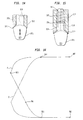
time. Referring to Figure 11, the movements of movable platen 921 are shown
diagrammatically, which will of necessity include the movement of the cores thereon.
Thus, when platen 921 moves from the position in Figure 9 to the position in Figure
11 a given point on the platen will follow curve A. The return movement will follow
curve B. As platen 921 moves away from platen 911 the section on curve A from
location 960 to 961 represents movement from the closed position of Figure 9 to that
point at which movement of core 920 with parison 925 thereon may occur laterally
without mechanical interference. As soon as location 961 is passed said point starts
its lateral movement which is subdivided into three (3) sections, namely between
locations 961 and 962 in which acceleration is taking place, then between 962 and
963 in which the velocity of the point is constant, followed by between 963 and 964
in which deceleration is taking place. Finally, locations 964 and 965 show the
approach to the blow mold and the position shown in Figure 16. Naturally, the actual
shapes of the curve segments will depend on the mass being moved, with the segment
being steeper the lighter the movement assembly. As indicated above, curve B
depicts the reverse movement. These movements can be effected by any
conventional means, e.g. fluid actuators or by cam action. If by fluid actuators, it is
readily possible to initiate their movement and thus also that of platen 921 by a limit
switch placed to be tripped by platen 921 as soon as said platen reaches the distance
from platen 911 at which the lateral movement of core 920 can take place unimpeded.
If by cam action, fixed cams in the shape of curves A and B of Figure 16 may be
used and platen 911 may be equipped with corresponding cam followers, to the effect
that the axial movement of platen 921 will at the same time induce its lateral
movement according to the cam path. Other means to produce the same result may
be employed so long as the lateral movement of platen 921 is effectively controlled
by its axial movement, whereby said lateral movement accommodates acceleration
and deceleration of platen 921 according to the mass to be moved therewith. The
advantage of this improved arrangement is evident from the gain in cycle time. Thus,
in the case referred to hereinabove the dry cycle of the injection clamping apparatus is
reduced from approximately 4 seconds to approximately 1.2 seconds, of which the
lateral shifting of platen 921 takes only 0.4 to 0.5 seconds including acceleration and
deceleration. This improvement is particularly noticeable in connection with
mechanical, e.g. toggle or crank clamping mechanisms which are favored for rapid
acting injection clamps over fluid actuated clamps. In the former, the clamping
apparatus, which is of the "fixed stroke" type can be used to induce the movement of
platen 21 during that portion of its opening and closing stroke respectively which is in
excess of the minimum clearance between core 920 and mold 917. Cores 920 and
940 are equipped with fluid passageways terminating in so-called blow slots 970 as
shown in Figure 14 in order to effect blowing of the preforms in the blow molds, as
is known in the art. If permanently open, the blow slot 970 is connected according to
conventional design of a source of pressure fluid and a source of vacuum via fluid
passageway 978 whereby the change from one to the other is effected by a
conventional valve in order for the dual function of the blow slot to be readily
accomplished as needed during injection and opening of the injection mold, and then
during blowing. The blow slot may be formed of two elements of the core, for
example leading element 971 and following element 972, that are capable of relative
movement as shown in Figure 14 by the arrow, with Figure 11 showing leading
element being relatively moveable, with element 971 having a leading bulb-like
portion 973 connected to a movable stem 974 which in turn is connected to a motive
means (not shown). It is necessary to control the opening and closing of blow slot
970 mechanically in the following sequence: the blow slot is closed and held in that
condition while injection of the plastic into the mold is initiated and almost
immediately thereafter is opened; alternatively, it may be kept closed until the filling
of the mold is accomplished and opened only thereafter. Vacuum is applied while the
blow slot is open and maintained as core 20 or 40 is moved away from injection
station 910 (see Figures 9 and 10). The blow slot remains open and vacuum is
maintained while the preform moves from the injection station into the blow station,
at which time, by suitable valving, the vacuum is broken and fluid pressure applied
inside the preform to expand it into the shape of the finished article. At the end of the
blowing cycle, the connection between the blow slot and the source of fluid pressure
is interrupted, but vacuum is not admitted inside the finished article. Accordingly, in
the case of an operable slot, the flow of fluid or connection to vacuum is controlled
by a valve system that operates as follows: open to vacuum; closed to vacuum, open
to pressureclosed to pressure, open to atmosphereclosed to pressure, closed to
vacuum; blow slot closed Figure 15 shows one embodiment of actuating the blow
slot 970. As shown, a spring 975 is provided, urging the movable element 971
forming the blow slot to open the latter. Stem 974 is provided with a fixed annular
bar 976. Spring 975 is affixed to stem 974 between bar 976 and internal ridge 977
on element 972. When inserted into the injection station, the entering plastic will
tend to counteract the force of spring 975 closing the blow slot. When the pressure of
the entering plastic is relieved, spring 975 will tend to open the slot again. However,
if no vacuum is applied, then atmospheric pressure will tend to close the slot or
counteract the spring. Accordingly, the spring force chosen has to be such as to
maintain the blow slot open against the atmospheric pressure so that vacuum may be
applied.
The total force due to atmosphere pressure counteracting the spring is of
course one atmosphere times the maximum projected area of the movable portion of
the core assembly; A2 π /4. Accordingly, the force of the spring will be chosen well
above that figure, for example, twice or three times that much, it being noted that the
pressure of the plastic during injection is many times higher so that even with a
stronger spring the blow slot will still be closed during the injection step. Thus, the
cores may be provided with means operative to close the blow slot under the pressure
of incoming plastic and to open the blow slot when the pressure of the incoming
plastic is relieved. If the blow slot is to be permanently open, it must of course be
held to a dimension precluding clogging thereof by penetration of the plastic while
under pressure. That dimension is accordingly chosen according to the viscosity of
the plastic at pressure molding temperature. In the case of very thin fluid plastics,
e.g. relatively low molecular weight polyethylene and nylon, it is not possible to
produce a narrow enough slot and to maintain it economically. In the case of most
amorphous plastics such as polystyrene, a permanently open slot may be used. As an
improvement, the faces of the corresponding blow core components forming the slot
are slightly tapered toward the outside as shown in Figures 14 and 15, i.e., the side
facing away from the core, and they are preferably coated with a substance that
prevents adhesion of the entering plastic to metal surfaces, e.g. teflon. In
consequence, any slight amount of penetration into the slot will be cured during the
blowing step, at which time the plastic that will thus have entered the blow slot will
be blown out. The above described apparatus features interact with the process,
particularly because a critical relationship exists between the temperature of the
plastic at any given stage and the rate and magnitude of the forming operation to
which it is subjected. The process injection blow-molding is of course aimed at
providing a predetermined shape of the finished article. In addition, in most
instances, as when converting brittle plastics into thin-walled objects the process is
used to improve the properties of the plastic, such as strength, ductility, resistance to
permeation, etc. by molecular orientation, the details of which are well known,
including the fact that the best levels of orientation are obtained by conducting the
forming process at the lowest temperature compatible with the glass transition range
of the given plastic that the chosen procedure is capable of.
In accordance with this invention, namely the manufacture of a bell fountain
drinking cup as illustrated in Figure 17(a) from polycarbonate, the following process
parameters can be used with the blow-molding apparatus and process as described in
U.S. 4,540,543 and above. Initially, the polycarbonate in the form of pellets is dried
to remove moisture. Drying conditions of 3.5 hours at 250°F have been found useful
in providing a polycarbonate which can be injection blow-molded into the permaware
containers of this invention. The polycarbonate plastic has to be pressure formed into
the parison rapidly, hence the molten plastic temperature is left relatively high at from
about 450°F to about 700°F, preferably, from about 500°F to about 650°F; and most
preferably, a temperature of about 545°F has been found to yield the desired parison.
Injection pressures of 1,000 to 3,000 psi can be used, with an injection pressure of
about 2,100 psi being most preferred. The parison has to be removed from the
parison mold after the shortest possible dwell therein in order to rapidly proceed to
the next molding cycle, yet without tending to adhere to the mold and become
deformed thereby. For permaware, which require a thicker parison, the time in the
parison mold must yield a stable parison. Dwell times in the parison mold to produce
the polycarbonate permaware of this invention range from about 1 to 3 seconds, with
2.5 seconds being most preferred. In general, the temperature of the parison has to
reach a level suitable for orientation during the short dwell in the parison mold and
the comparatively short time, shortened by the clamp action described herein, during
which the parison is transported into the blow mold.The temperature at which the
deformation of the parison, i.e., blowing takes place, should be uniformly maintained
while the parison is expanding and until it contacts the parison mold. Temperatures
ranging from about 250°F to about 500°F, and most preferably at about 285°F can be
used. In no case must the parison be damaged, nor deformed in the course of any
operation to which it is subjected, except of course blowing. A blowing pressure of
from about 100 to about 500 psi, preferably, from about 200 to about 400 psi, and
most preferably at about 250 psi, is employed. Figures 17(a) through 17(c) illustrate
a bell fountain tumbler 979 injection blow-molded in accordance with the present
invention. The tumbler can be prepared using a split blow cavity employing two
separate halves which can be configured exactly the same or differently to provide
separate design elements to the tumbler. For example, tumbler 979 can optionally be
provided with an embossing design defined by embossed flat surfaces 988 and ridges
1004 which circumscribe the embossed areas 988. The design is operative as a grip
for a user since the smooth sidewall is substantially altered. Such tumblers are
typically characterized by a seam 1001 along the longitudinal axis of the tumbler.
The tumbler 979 has a base portion 980, a sidewall portion 981 and an upper circular
rim portion 982 which extends about the periphery 983 of an opening 984 of tumbler
979. Base portion 980 of tumbler 979 is integrally formed with the rest of the
tumbler and includes a bottom 985, a base sidewall 987, and an inner face 989
attached integrally to sidewall 981. Tumbler 979 as shown is characterized as a "bell
fountain" tumbler in which sidewall 981 extends upwardly to convex portion 990
which extends to concave portion 991 and extends to fortified rim 982. Rim 982 is
integrally formed with sidewall 981 and is a continuous generally circular or oval,
solid polymer bead extending about periphery 983 of opening 984. Rim 982 has the
advantages that it is rounded and does not snag on the mold or snag with a cup cover
as a top curl does. For another advantage, a bead type top rim can more compactly
provide rigidity and strength to a cup than does a top curl, with less width. While
polymer bead rim 982 is shown as circular in cross section, other profiles may be
suitable for example, conic sections such as ellipsoid shapes or truncated conic
sections or profiles such as truncated conic sections including a semi-circle or a half
ellipse. Rim 982 has a width W which is defined by the difference between an inner
diameter 993 and an outer diameter 994 of rim 982 and a height H which is the
distance over which width W extends. Width W is thicker than the rest of sidewall
981. Sidewall 981 is substantially uniform in thickness on the entire tumbler. In a
preferred form of the bell fountain tumbler shown, sidewall 981 has at thickness of 80
mils, height H is approximately 100 mils and width W of rim 982 is approximately
100 mils. Also, base sidewall 987 preferably has a height or thickness of about 100
mils. While the base sidewall 987 can have a height up to 8 times the thickness of
sidewall 81, it has been found that under harsh washing conditions, the base tends to
deteriorate if it is about 150 mils or more in the polycarbonate tumbler shown. The
overall height of the preferred tumbler 979 is 6.625 inches, inner diameter 993 is 3.25
inches, base diameter is 2.325 inches and shoulder 990 has an inner diameter of 3.5
inches. As noted above, tumblers in accordance with the present invention are
produced by injection blow-molding thermoplastic optically transparent polymers.
As discussed above, crystal polystyrene available from Dow Corporation of
Midland, Michigan, grade 685d have been used to produce tumblers by the method of
United States Patent No. 4,540,543. However, permaware products formed from
polystyrene polymers using the injection blow-molding process described above do
not have a consistent durability, are brittle and tend to break. Advantageously, the
polycarbonate tumblers of the present invention provide a product having the same
desirable clarity of polystyrene tumblers but are more durable such that the
polycarbonate tumblers do not break during normal use. It is often desirable to
incorporate at the bottom of a tumbler identifying indicia, including the location of
the manufacturer, trademarks, even to mold into the bottom certain configurations
which enable the tumbler to be printed or packaged.
Referring to Figure 17(b), it can be seen that the bottom of base 985 has been
molded to include a concave, flat portion 986 which includes a rim 1005, both of
which locations can be used to imprint product identifying indicia (not shown).
Figure 17(b) also shows where a lug 1006 has been molded into the bottom 985 of
base 980. Molded lug 1006 can be used to align the tumbler during any subsequent
printing operation. Previous to this invention, the incorporation of such molded
indicia or components to the base of a blow-molded article, in particular, an article in
which the wall thickness was greater than 50 mil, required a separate noncontinuous
step in which the article, such as a tumbler needed to be taken from the blow mold at
an elevated temperature, and conveyed by a separate conveyor structure to a stamping
operation. For relatively thick walled structures including those having a wall
thickness of greater than 50 mils, the molding of the indicia could not take place
during blow-molding since the fluid pressure during the blowing step could not press
the parison to be molded sufficiently hard against a mold surface to provide
acceptable indicia or deep structural configurations to the surface such as the printing
lug 1006 shown in Figure 17(b). In a novel aspect of the present invention, the
polycarbonate tumbler of the present invention can be blow-molded and the base
thereof reconfigured in a continuous manner without the need to remove the tumbler
from the blow mold and convey the tumbler away from the apparatus to a separate
stamping operation. The base molding method and apparatus which are novel to the
present invention can be described by referring to Figure 18. Thus, after removal of
the core from the blow-molding station, as described above, an alternative ejection
core can be inserted into the blow cavity which contains the blow-molded container.
This alternative ejection core provides a slight pressure against the inside surface of
the container pressing the bottom surface of the container against a preformed mold.
More specifically, shown in Figure 18 is the blow cavity 1010 of a blow mold such
as a blow station 913 as shown in Figure 11. Within the blow cavity is the blow-molded
tumbler 1012 which includes a sidewall 1014 and a base 1016 which has a
bottom surface 1018 which is to be provided with indicia or other structural
configurations such as printing lug 1006 as shown in Figure 17(b).
In accordance with the molding operation of the present invention, after the
blow-molding step and once the core has been removed from the
blow mold 1010 of
Figure 18, for example, an
ejection core 1020 is inserted into the
blow cavity 1010
and the
tumbler 1012 which remains therein.
Ejection core 1020 is wide enough to
contact the inside edge of
sidewall 1014 near or at the
base 1016 of
tumbler 1012.
Such contact is shown at
location 1022.
Bottom edge 1024 of
ejection core 1020
contacts the inside surface of
base 1016 and pushes the
tumbler 1012 against a
mold
1026. Ejection core 1020 can also include a
circumferential lip 1021 which engages
the
lip 1013 of
tumbler 1012 so as to aid in pushing
tumbler 1012 uniformly against
the surface of
mold 1026. In
Figure 18,
mold 1026 is shown containing a
mold
configuration 1028 which is capable of forming a printing lug on the
bottom 1018 of
base 1016 such as equivalent to
printing lug 1006 shown in
Figure 17(b). Mold 1026
can be secured to blow
cavity 1010 via threaded
connector 1027. It has been found
that the mechanical pressure of
ejection core 1020 against the inside surface of
base
1016 provides adequate pressure against the
mold 1026 to adequately stamp any
indicia or other configuration into the base of the tumbler. Typically, the pressure of
the
ejection core 1020 against the
base 1016 within the blow cavity to mold or stamp
the base takes approximately 0.5 second.
Mold 1026 can include a
cooling channel
1030 to provide the cooling of the base subsequent to the molding operation.
Likewise,
ejection core 1020 can also be provided with a
cooling channel 1032. In
each of
cooling channels 1030 and
1032, cooling fluids such as water can be
circulated therein to provide the proper temperature. Subsequent to the molding or
stamping operation, the
ejection core 1020 is removed from the blow cavity. Since
the
mandrel 1020 contacts the
inside sidewall 1014 of
tumbler 1012, the tumbler is
removed from the blow cavity as well and transferred to any conveying station as
described previously. The
ejection core 1020 is an alternative to the
ejection core 950
shown in
Figures 11, 12 and
13 and can be attached to a motive means as described
above with respect to
core 950 to provide a continuous process of injection blow-molding
and molding the base of the tumbler. Another improvement in this invention
for injection blow-molding permaware polycarbonate tumblers in which a sidewall
thickness of greater than 950 mils is provided is shown in
Figure 19.
Figure 19 is
an alternative blow mold cavity configuration which is different than, for example,
the blow cores shown in
Figures 14 and
15. Thus, in the previous description,
blowing of the parison into the molded tumbler was achieved by directing fluid
through a blow slot in the core which directed the fluid at the base of the parison
mold. Subsequently, the fluid pressure would work its way up the mold and be
vented from the entrance of the mold. With respect to the tumbler, the initial fluid
pressure would be at the base of the tumbler and work its way along the sidewall to
the tumbler opening. In accordance with this invention, it has been found that a
uniform blow-molded tumbler can be better achieved by directing the fluid pressure
during the blow stage from the top of the mold and working down toward the base of
the blow cavity or, with respect to the tumbler, blowing the parison at the opening of
the tumbler and working down toward the base of the tumbler. Such configuration is
shown in
Figure 19 which includes a
blow cavity 1040 into which has already been
inserted the
core 1042 which contains the injected molded
parison 1044 contained
along the outside surface of
core 1042. The
blow cavity 1040 includes a
mold 1046
in the shape of the bell fountain tumbler shown in
Figure 17(a). The
core 1042
includes a
blow vent 1048 which releases a fluid into the
mold 1046 of
blow cavity
1040 near the entrance thereof or with respect to the tumbler, near the opening of the
tumbler. The fluid pressure travels down the
core 1042 blowing and pressing the
parison 1044 against
mold 1046 from the top of the parison to the
base 1050 of the
parison.
Blow cavity 1040 also includes the
base mold 1026 as described in
Figure
18 which allows the molding of the base of the blow-molded tumbler once
core 1042
is removed and
ejection core 1020 is inserted.
Mold 1026 includes a
vent 1052
connected to blow
cavity 1040 to vent excess fluid pressure. It has been found that a
more uniform sidewall can be achieved by blowing from the opening of the
parison/tumbler to the base thereof. This method of blowing the parison has
previously been done to blow polystyrene disposable containers but is not believed to
have been done with resins other than polystyrene and not to form permaware
tumblers having sidewall thicknesses of greater than 50 mils.The reusable containers
of the present invention are formed from aromatic polycarbonates preferably having a
weight average molecular weight of from about 10,000 to 200,000, most preferably
from about 20,000 to 80,000, and most particularly a melt flow rate range of from
about 10 to 22 g/10 min (ASTM D-1238) and which are prepared by methods known
to those skilled in the art and more particularly by methods disclosed in U.S. Pat.
Nos. 3,028,365, 2,999,846, 3,248,414, 3,153,008, 3,215,668, 3,187,065, 2,964,794,
2,970,131, 2,991,273 and 2,999,835, all incorporated herein by reference.The
aromatic polycarbonates useful in practice of the invention are produced by reacting
di-(monohydroxyaryl)-alkanes (bisphenols) or dihydroxybenzenes and substituted
dihydroxybenzenes with derivatives of carbonic acid such as carbonic acid diesters,
phosgene, bis-chlorocarbonic acid esters of di-(monohydroxyaryl)-alkanes and the
bis-chlorocarbonic acid esters of the dihydroxy-benzenes and the substituted
dihydroxy-benzenes.By aromatic polycarbonate, in the sense of the present invention,
there are understood homopolycarbonate and copolycarbonate resins which are based,
for example, on one or more of the following bisphenols: hydroquinone, resorcinol,
dihydroxydiphenyls, bis-(hydroxyphenyl)-alkanes, bis-(hydroxyphenyl)-cycloalkanes,
bis-(hydroxyphenyl)-sulphides, bis-(hydroxyphenyl)-ethers, bis-(hydroxyphenyl)-ketones,
bis-(hydroxyphenyl)-sulphoxides, bis-(hydroxyphenyl)-sulphones
and a, a-bis-(hydroxyphenyl)-diisopropylbenzenes, as well as heir
nuclear-alkylated and nuclear-halogenated compounds. These and further suitable
aromatic dihydroxy compounds are described, for example, in U.S. Pat. Nos.
3,028,365, 2,999,835, 3,148,172, 3,271,368, 2,991,273, 3,271,367, 3,280,078,
3,014,891 and 2,999,846 (all incorporated herein by reference), in German
Offenlegungsschriften (German Published Specifications) 1,570,703, 2,063,050,
2,063,052, 2,211,956 and 2,211,957, in French Patent Specification No. 1,561,518
and in the monograph "
H Schnell, Chemistry and Physics of Polycarbonates,
Interscience Publishers, New York, 1964". Preferred bisphenols are those of the
formula I:
in which R is identical or different and denotes H, C
1-C
4 -alkyl, Cl or Br; preferably
H or C
1-C
4 -alkyl, and in which X is a bond, C
1-C
8 -alkylene, C
2-C
8-alkylidene,
C
5 -C
15 -cycloalkyene, C
5 -C
15 --cycloalkylidene, -S-, -SO
2 -, -SO-, -CO- or
Examples of these bisphenols are: 4,4'-dihydroxydiphenyl, 2,2-bis-(4-hydroxyphenyl)-propane
(bisphenol A), 2,4-bis-(4-hydroxyphenyl)-2-methylbutane,
1,1-bis-(4-hydroxyphenyl)-cyclohexane, α, α-bis-(4-hydroxyphenyl)-p-diisopropyl-benzene,
2,2-bis-(3-methyl-4-hydroxyphenyl)-propane, 2,2-bis-(3-chloro-4-hydroxyphenyl)-propane,
bis-(3,5-dimethyl-4-hydroxyphenyl)-methane, 2,2-bis-(3,5-dimethyl-4-hydroxyphenyl)-propane,
bis(3,5-dimethyl-4-hydroxyphenyl)-sulphone,
2,4-bis-(3,5-dimethyl-4-hydroxyphenyl)-methylbutane, 1,1-bis-(3,5-dimethyl-4-hydroxyphenyl)-cyclohexane,
α,α-bis-(3,5-dimethyl-4-hydroxyphenyl)-p-diisopropyl-benzene,
2-2-bis-(3,5-dichloro-4-hydroxyphenyl)-propane and 2,2-bis-(3,5-dichloro-4-hydroxyphenyl)-propane
and 2,2-bis-(3,5-dibromo-4-hydroxyphenyl)-propane
(tetrabromo bisphenol A).
Examples of particularly preferred bisphenols are: 2,2-bis-(4-hydroxyphenyl)-propane,
2,2-bis-(3,5-dimethyl-4-hydroxyphenyl)-propane, 2,2-bis-(3,5-dichloro-4-hydroxyphenyl)-propane,
2,2-bis-(3,5-dibromo-4-hydroxyphenyl)-propane and 1,1-bis-(4-hydroxyphenyl)-cyclohexane.
Preferred aromatic polycarbonates are those which are based on one or more
of the bisphenols mentioned as being preferred. Particularly preferred
copolycarbonates are those based on 2,2-bis-(hydroxyphenyl)-propane and one of the
other bisphenols mentioned as being particularly preferred. Further particularly
preferred polycarbonates are those based solely on 2,2-bis-(4-hydroxyphenyl)-propane
or 2,2-bis-(3,5-dimethyl-4-hydroxyphenyl)-propane.
The aromatic high-molecular weight polycarbonates can be branched due to
the incorporation of small amounts, preferably of between about 0.05 and 2.0 mol %
(relative to diphenols employed), or trifunctional or more than trifunctional
compounds, especially compounds with three or more phenolic hydroxyl groups.
Polycarbonates of this type are described, for example, in German
Offenlegungsschriften (German Published Specifications) 1,570,533, 1,595,762,
2,116,974 and 2,113,347, British Patent Specifications No. 3,544,514 (incorporated
herein by reference).
Some examples of compounds with three or more than three phenolic
hydroxyl groups which can be used are phloroglucinol, 4,6-dimethyl-2,4,6-tri-(4-hydroxyphenyl)-heptane-2,4,6-dimethyl-2,4,6-tri-(4-hydroxyphenyl)-heptane,
1,4,5-tri-(4-hydroxyphenyl)-benzene,
1,1,1-tri(4-hydroxyphenyl)ethane tri-(4-hydroxyphenyl)-phenylmethane,
2,2-bis-[4,4-bis-(4-hydroxyphenyl)-cyclohexyl]-phenol,
2,6-bis-(4-hydroxyphenyl-isopropyl)-phenol, 2,6-bis-(2-hydroxy-5'-methylbenzyl)-4-methylphenol,
2-(4-hydroxyphenyl)-2-(2,4-dihydroxyphenyl)-propane,
hexa(4-(4-hydroxyphenylisopropyl)phenyl) orthoterephthalic acid ester,
tetra-(4-hydroxyphenyl)-methane, tetra(4-(4-hydroxyphenylisopropyl)-phenoxy)-methane
and 1,4-bis-((4',4"-dihydroxytriphenyl)-methyl)-benzene. Some of the other
trifunctional compounds are 2,4-dihydroxybenzoic acid, trimesic acid, cyanuric
chloride and 3,3-bis-(4-hydroxyphenyl)-2-oxo-2, 3-dihydroindole.
Particularly preferred polycarbonates which can be used to injection blow
mold the permaware containers of this invention are the Calibre 200 Series
polycarbonates from Dow Chemical Canada, Inc., Sarnia, Ontario. Specifically,
Calibre 200-22 has been found particularly useful.
In high speed operation, such as the one at which this invention is aimed,
several factors have to be reconciled: the plastic has to be pressure formed rapidly,
hence its temperature is left relatively high; the parison has to be removed from the
parison mold after the shortest possible dwell therein, in order to proceed to the next
molding cycle, all without tending to adhere to the mold and becoming deformed
thereby; the temperature of the parison has to reach a level suitable for orientation
during the short dwell in the parison mold and the comparatively short time,
shortened by the clamp action described herein, during which the parison is
transported into the blow mold; the temperature at which the deformation of the
parison, i.e., blowing takes place should be uniformly maintained while the parison is
expanding and until it contacts the parison mold; in no case must the parison be
damaged, nor deformed in the course of any operation to which it is subjected, except
of course blowing.
A typical use of this invention in another aspect will serve as an example
hereinbelow, namely the manufacture of a thin-walled drinking cup of generally
known configuration, from polystyrene, e.g. Styron 685 made by the Dow Chemical
Company. In order to obtain satisfactory filling of the mold at a fast rate, it is
injected at 560°-570°F. The parison tends to adhere to the parison mold cavity wall
until its temperature drops to approximately 150°F. The newly molded parison, with
a wall thickness increasing from 0.3 mm to 0.6mm from its open end towards its
bottom dwells in the parison mold for approximately 0.8 seconds with the mold
cavity wall at a temperature of 140°F which is long enough for the parison to become
removable without sticking. The core in turn is kept at a temperature of 260°F for the
most part, with the region near the blow slot separately controlled at 220°F or slightly
lower to minimize penetration of the plastic thereinto.
As a result, temperatures of the inner and outer surface of the parison are so
balanced under action of the core and mold respectively that said parison remains
highly deformable while being readily separated from the parison mold cavity and
transferred to the blow mold. Once placed into the blow mold, a blowing pressure of
100-300 psi is applied which may be accompanied by forward movement of pusher
plate 952 in order to center the parison or the movable element of the blow core
shown in Figure 15, to stretch it into contact with the blow mold. If such movement
of the blow core element is used, it must not precede initiation of blowing, so as to
assure that no friction or adhesion exists between the parison and the core while the
former is being moved axially.
The injection blow-molding process and apparatus disclosed in U.S.
4,540,543 have been used to form containers, cups, tumblers and the like from
thermoplastic optically transparent polymers, in particular, from polystyrene. Such
containers were disposable having a nominal sidewall thickness substantially less
than 50 mils. Permaware products, such as those having thicknesses of greater than
50 mils, and formed from polystyrene polymers using the injection blow-molding
process described above do not have a consistent durability, are brittle and tend to
break. Accordingly, there has been a need to find alternative polymers which can be
injection blow-molded using the process described above and which can provide a
product having the same desirable clarity of polystyrene tumblers but which are more
durable.
In accordance with still yet another aspect of the present invention, it has been
found that the injection blow-molding process described in U.S. 4,540,543 can be
operated to form hollow containers using resins other than unfilled polystyrene which
is the only polymer disclosed in the mentioned patent. Thus, it has been found that
polycarbonate, polyethylene terephthalate, polycarbonate and ABS mixtures, acrylic
resins, clarified polypropylene and polyvinylchloride, as well as the filled polymers
described above, can be successfully injection blow-molded into transparent
containers. Additionally, the other resin or mixed resin alternatives to unfilled
polystyrene which are useful in this invention include filled resins such as filled
polystyrene, polycarbonate, polyethylene terephthalate, mixtures of polycarbonate
and ABS resins, acrylic resins, clarified polypropylene and polyvinyl chloride. It is
most advantageous that the filled resin systems have the flowability necessary for
injection blow-molding, can maintain at least the initial strength of the unfilled resin
and, in particular, remain transparent which is a highly desired property when
injection blow-molding containers such as plastic drinking tumblers or "glasses".
Accordingly, the process of the present invention is particularly useful in injection
blow-molding transparent drinking containers from filled resins which have been
characterized as "nano-composites". Nano-composites are reinforced resins which
comprise the resins enumerated above and nanometer-sized filler particles. It has
been found that resins containing small amounts of approximately 2-5% of the
nanometer-sized particles can provide improvements in mechanical and thermal
properties, improvements in gas barrier and flame resistance and do not reduce the
light transmission of the resins inasmuch as the nanometer-sized particles are in the
same size range as visible light wave lengths. A discussion of nano-composites is
provided in Plastics Technology, June, 1999. Accordingly, nano-composites can
advantageously be used to injection blow mold drinking containers such as tumblers
and the like. Thus, not only would the transparent nature of the resins be maintained,
but the strength of the resin could be improved. For polystyrene, the use of a
nanometer-sized filler could improve the strength of the resin and provide more uses
of this resin than for just disposable tumblers.
At present, nanometer-sized clay has been used to form nano-composites. For
example, montmorillonite, which is a layered alumino-silicate having individual
platelets that measure on the order of 1 micron diameter and have an aspect ratio of
1,000:1 have been added to nylon. Suppliers of the nanometer montmorillonite are
Nanocor, Inc. And Southern Clay Products. For some of the above listed resins, it
may be useful to chemically modify the surface of the montmorillonite inasmuch as
this hydrophilic clay may not be compatible with the more hydrophobic resins.
Surface treatments can include exchanging the inorganic cations on the surface of the
clay with materials which can induce hydrogen bonding with the resin including
hydrogen cations, ammonium cations, silane cations and the like. Other fillers can be
formed chemically or ground to the appropriate size and used as fillers for the
injection blow moldable resins of this invention. For example, inorganic or organic
pigments such as zinc oxide, or titanium oxide can be used. Even plastic fillers can
be provided in nanometer sizes and added to the blow moldable resins.
The nanocomposites can be formed by forming the resin itself in the presence
of the nano-filler particles or by simply melt compounding the formed resin with the
nano-filler particles. During the melt compounding method of forming nano-clay
composites, it has been found necessary to delaminate the clay particles sufficiently
so that the ultimate level of reinforcement and transparency can be achieved.
The injection blow-molding of these alternative resins can be used to form
both disposable and permaware containers having nominal sidewall thicknesses of
from 10 to 50 mils and greater than 50 mils to 500 mils, respectively. While each of
the resins may need to be processed differently from the others, typically, the molten
resin is pressure formed into the parison rapidly, at a relatively high temperature
ranging from about 300° to 850°F so as to form the desired parison. Injection
pressures of 1,00 to 3,500 psi can be used. Dwell times of the parison in the parison
mold will generally range from 0.5 to 3.5 seconds depending on the setting ability of
the polymer used and the thickness of the article to be formed. The temperature at
which the deformation of the parison, i.e., blow-molding, takes place should be
uniformly maintained while the parison is expanding and until it contacts the blow
cavity mold. Temperatures ranging from about 200° to 600°F can be used. In no
case must the parison be damaged, nor deformed in the course of any operation to
which it is subjected, except of course blowing. A blowing pressure of from about
100 to 500 psi, preferably from about 200 to 400 psi can be employed.
It is often desirable to incorporate at the bottom of a tumbler identifying
indicia, including the location of the manufacturer, trademarks, even to mold into the
bottom certain configurations which enable the tumbler to be printed or packaged.
For example, one or more molded lugs can be molded into the base of the container
and used to align the container during any subsequent printing operation. Previous to
this invention, the incorporation of such molded indicia or components to the base of
a blow-molded article, in particular, an article in which the wall thickness was greater
than 50 mil, required a separate noncontinuous step in which the article, such as a
tumbler needed to be taken from the blow mold at an elevated temperature, and
conveyed by a conveyor structure to a separate stamping operation. For relatively
thick walled structures including those having a wall thickness of greater than 50
mils, the molding of the indicia could not take place during blow-molding since the
fluid pressure during the blowing step could not press the parison to be molded
sufficiently hard against a mold surface to mold acceptable indicia or deep structural
configurations such as a printing lug into the surface.
In a novel aspect of the present invention, containers such as cups, tumblers
and the like can be blow-molded and the base thereof reconfigured in a continuous
manner without the need to remove the tumbler from the blow mold and convey the
tumbler away from the apparatus to a separate stamping operation.
The base molding method and apparatus which are novel to the present
invention in one embodiment can be described by referring to Figure 18. Thus, after
removal of the core from the blow-molding station, as described above, an alternative
ejection core can be inserted into the blow cavity which contains the blow-molded
container. This alternative ejection core provides a slight pressure against the inside
surface of the cup pressing the bottom surface of the cup against a preformed mold.
More specifically, shown in Figure 18 is the blow cavity 1010 of a blow mold such
as a blow station 913 as shown in Figure 11. Within the blow cavity is the blow-molded
tumbler 1012 in the form of a "bell fountain" tumbler which includes a
sidewall 1014 and a base 1016 which has a bottom surface 1018 which is to be
provided with indicia or other structural configurations such as a printing. In
accordance with the molding operation of the present invention, once the core has
been removed from the blow mold 1010 subsequent to the blowing step, an ejection
core 1020 is inserted into the blow cavity 1010 and the tumbler 1012 which remains
therein. Ejection core 1020 is wide enough to contact the inside edge of sidewall
1014 near or at the base 1016 of tumbler 1012. Such contact is shown at location
1022. Bottom edge 1024 of ejection core 1020 contacts the inside surface of base
1016 and pushes the tumbler 1012 against a mold 1026. Ejection core 1020 can also
include a circumferential lip 1021 which engages the lip 1013 of tumbler 1012 so as
to aid in pushing tumbler 1012 uniformly against the surface of mold 1026. In
Figure 18, mold 1026 is shown containing a mold configuration 1028 which is
capable of forming a printing lug on the bottom 1018 of base 1016. Mold 1026 can
contain other mold features including indicia or trademark logos and the like. Mold
1026 can be secured to blow cavity 1010 via threaded connector 1027. It has been
found that the mechanical pressure of ejection core 1020 against the inside surface of
base 1016 provides adequate pressure against the mold 1026 to adequately stamp any
indicia or other configuration into the base of the tumbler. Typically, the pressure of
the ejection core 1020 against the base 1016 within the blow cavity to mold or stamp
the base takes approximately 0.5 second. Mold 1026 can include a cooling channel
1030 to provide the cooling of the base subsequent to the molding operation.
Likewise, ejection core 1020 can also be provided with a cooling channel 1032. In
each of cooling channels 1030 and 1032, cooling fluids such as water can be
circulated therein to provide the proper temperature. Subsequent to the molding or
stamping operation, the ejection core 1020 is removed from the blow cavity. Since
the mandrel 1020 contacts the inside sidewall 1014 of tumbler 1012, the tumbler is
removed from the blow cavity as well and transferred to any conveying station as
described previously. The ejection core 1020 is an alternative to the ejection core 950
shown in Figures 11, 12 and 13 and can be attached to a motive means as described
above with respect to core 950 to provide a continuous process of injection blow-molding
and molding the base of the tumbler.
Another improvement relative to U.S. 4,540,543 is shown in Figure 19.
Figure 19 is an alternative blow mold cavity configuration which is different than, for
example, the blow cores shown in Figures 14 and 15. Thus, in the previous
description, blowing of the parison into the molded tumbler was achieved by
directing fluid through a blow slot in the core which directed the fluid at the base of
the parison mold. Subsequently, the fluid pressure would work its way up the mold
and be vented from the entrance of the mold. With respect to the tumbler, the initial
fluid pressure would be at the base of the tumbler and work its way along the sidewall
to the tumbler opening. In accordance with this invention, it has been found that a
uniform blow-molded tumbler can be better achieved by directing the fluid pressure
during the blow stage from the top of the mold and working down toward the base of
the blow cavity or, with respect to the tumbler, blowing the parison at the opening of
the tumbler and working down toward the base of the tumbler. Such configuration is
shown in Figure 19 which includes a blow cavity 1040 into which has already been
inserted the core 1042 which contains the injected molded parison 1044 contained
along the outside surface of core 1042. The blow cavity 1040 includes a mold 1046
in the shape of the bell fountain tumbler. The core 1042 includes a blow vent 1048
which releases a fluid into the mold 1046 of blow cavity 1040 near the entrance
thereof or with respect to the tumbler, near the opening of the tumbler. The fluid
pressure travels down the core 1042 blowing and pressing the parison 1044 against
mold 1046 from the top of the parison to the base 1050 of the parison. Blow cavity
1040 also includes the base mold 1026 as described in Figure 18 which allows the
molding of the base of the blow-molded tumbler once core 1042 is removed and
ejection core 1020 is inserted. Mold 1026 includes a vent 1052 connected to blow
cavity 1040 to vent excess fluid pressure. It has been found that a more uniform
sidewall can be achieved by blowing from the opening of the parison/tumbler to the
base thereof. This method of blowing the parison has previously been done to blow
polystyrene disposable containers but is not believed to have been done with resins
other than polystyrene and not to form permaware tumblers having sidewall
thicknesses of greater than 50 mils.
Optical/Physical Properties
The inventive tumblers characteristically exhibit enhanced optical properties
and crack resistance over prior art disposable cups. Unless otherwise indicated, cups
described below are fabricated from unfilled resins. There is shown in Table 2 below
a comparison of haze values of an injection blow-molded tumbler of
Figure 8 made
from PET with corresponding thermoformed cups.
| Optical Properties HAZE VALUES |
| | Injection Blow-Molded Tumbler of Figure 8 (PET) | Thermoformed PET Cup 1 | Thermoformed PET Cup 2 |
| 1 | 1.33 | 4.34 | 3.97 |
| 2 | 1.22 | 2.82 | 2.94 |
| 3 | 1.38 | 3.00 | 7.92 |
| 4 | 1.41 | 3.13 | 4.62 |
| 5 | 1.91 | 2.98 | 4.42 |
| 6 | 1.48 | 2.52 |
| Avg | 1.46 | 3.13 | 4.77 |
| Std | 0.239 | 0.628 | 1.875 |
Tumblers with a fortified, beaded rim produced in accordance with the present
invention likewise exhibit improved toughness over cups with a "U" shaped upper
rim as are known. In this regard, a test was devised to simulate impact resistance as
follows:
The tumblers (or tumbler stack in the case of a nested column) were clamped
about their bases to be in a free-standing position and a cylindrical suspended weight
was positioned to be at rest with its cylinder wall adjacent the rim of the tumbler. The
weight was then drawn to a predetermined angle from the vertical and released. The
angle with vertical at failure was recorded and the energy dissipated at impact was
calculated based on the height to which the cylindrical weight was raised above the
rest position.
Utilizing the above procedure, polystyrene cups having the general
characteristics of the cups of
Figure 8 ("beaded") were compared with similar cups
with a "U" shaped brim. The cups of the invention had a wall thickness of about 15
mils and a bead thickness of 63.7 mils about its brim. Results appear in Table 3,
wherein it can be seen the cups of the invention exhibit an energy to failure of nearly
twice that of cups with a "U" shaped brim.
| Pendulum Test Energy to Failure for Beaded and "U" Shaped Brim Polystyrene Cups (Nested Cups) |
| Cup ID | Pendulum Weight lbs | Pendulum Length inches | Pendulum Angle At Failure Degree | Energy to Failure lb-in | Energy to Failure Average |
| Beaded | 0.941816 | 25.5 | 20 | 1.45 |
| Beaded | 0.941816 | 25.5 | 25 | 2.25 |
| Beaded | 0.941816 | 25.5 | 25 | 2.25 |
| Beaded | 0.941816 | 25.5 | 25. | 2.25 |
| Beaded | 0.941816 | 25.5 | 25 | 2.25 | 2.09 |
| "U" | 0.941816 | 25.5 | 20 | 1.45 |
| "U" | 0.941816 | 25.5 | 15 | 0.82 |
| "U" | 0.941816 | 25.5 | 15 | 0.82 |
| "U" | 0.941816 | 25.5 | 15 | 0.82 |
| "U" | 0.941816 | 25.5 | 20 | 1.45 | 1.07 |
The material from which the cups are made likewise affects the toughness of
the product as does the various design elements of the tumbler. Utilizing the above
procedure (with tighter clamping of the cups) tumblers having the general
characteristics of Figures 3(a) - 3(c) were tested for impact resistance as indicated in
Table 4, as well as for crush loads and deflections (Instron).
The various tumblers of Table 4 had the characteristics noted as well as the
following:
The particular grade of PET employed for Tumbler C was MN058, available from
Eastman Chemicals, Kingsport, Tennessee.
The material employed likewise has a corresponding effect on the impact
resistance of the cups of Figure 8. Utilizing the above procedures, cups designed in
accordance with Figure 8 having a volume of 16 ounces, a wall thickness of 15 mils
and a rim bead diameter of 0.0637 inches were fabricated and tested as shown in
Table 5.
It can be seen from Table 5 that PET cups with dimensions similar to the
polystyrene cups of Table 3 exhibit greatly enhanced impact resistance.
Still yet another material useful for the present invention is K resin (Phillips
Petroleum). Utilizing the procedures detailed above, there is shown in Table 6 a
comparison of a polystyrene tumbler (Sample G) having the configuration of the
tumbler of Figure 8 hereof with a K resin/polystyrene (11.5% butadiene) tumbler
(Sample H) having the configuration of Figure 8. The tumbler of Sample H was
made with a K resin having 24.5 wt.% butadiene blended with polystyrene.
K resin is a copolymer of styrene and butadiene and is available from Phillips
Petroleum, Bartlesville, Oklahoma. Particularly preferred grades included from about
2 to about 40 wt.% butadiene.
It can be seen from Table 6 that K resin tumblers in accordance with the
invention exhibit high impact resistance.
The polymeric composition of this invention may further contain one or more
agents to improve the impact strength, i.e., an impact modifier other than or in
addition to butadiene/styrene copolymers.
So-called core-shell polymers built up from a rubber-like core on which one
or more shells have been grafted may be used. The core usually consists substantially
of an acrylate rubber or a butadiene rubber. One or more shells have been grafted on
the core. Usually these shells are built up for the greater part from a vinylaromatic
compound and/or a vinylcyanide and/or an alkyl(meth)acrylate and/or (meth)acrylic
acid. The core and/or the shell(s) often comprise multi-functional compounds which
may act as a cross-linking agent and/or as a grafting agent. These polymers are
usually prepared in several stages.
Olefin-containing copolymers such as olefin acrylates and olefin diene
terpolymers can also be used as impact modifiers in the present compositions. An
example of an olefin acrylate copolymer impact modifier is ethylene ethylacrylate
copolymer available from Union Carbide as DPD-6169. Other higher olefin
monomers can be employed as copolymers with alkyl acrylates, for example,
propylene and n-butyl acrylate. The olefin diene terpolymers are well known in the
art and generally fall into the EPDM (ethylene propylene diene) family of
terpolymers. They are commercially available such as, for example, EPSYN 704 from
Copolymer Rubber Company. They are more fully described in U.S. Patent No.
4,559,388, incorporated by reference herein.
Various rubber polymers and copolymers can also be employed as impact
modifiers. Examples of such rubbery polymers are polybutadiene, polyisoprene, and
various other polymers or copolymers having a rubbery dienic monomer.
Styrene-containing polymers can also be used as impact modifiers. Examples
of such polymers are acrylonitrile-butadiene-styrene, styrene-acrylonitrile,
acrylonitrile-butadiene-alpha-methylstyrene, styrene-butadiene, styrene butadiene
styrene, diethylene butadiene styrene, methacrylate-butadiene-styrene, high rubber
graft ABS, and other high impact styrene-containing polymers such as, for example,
high impact polystyrene. Other known impact modifiers include various elastomeric
materials such as organic silicone rubbers, elastomeric fluorohydrocarbons,
elastomeric polyesters, the random block polysiloxane-polycarbonate copolymers,
and the like. The preferred organopolysiloxane-polycarbonate block copolymers are
the dimethylsiloxane-polycarbonate block copolymers in some embodiments.
Injection blow-molded tumblers may be produced in accordance with the
present invention utilizing polymeric compositions filled with conventional inorganic
fillers such as talc, mica, wollastonite and the like, wherein the polymer component
is, for example, a polyester, a polystyrene homopolymer or copolymer, or a
polyolefin. While any suitable polymer may be used, polypropylene polymers which
are suitable are preferably selected from the group consisting of isotactic
polypropylene, and copolymers of propylene and ethylene wherein the ethylene
moiety is less than about 10% of the units making up the polymer, and mixtures
thereof. Generally, such polymers have a melt flow index from about 0.3 to about 4,
but most preferably the polymer is isotactic polypropylene with a melt-flow index of
about 1.5. In some preferred embodiments, the melt-compounded composition from
which the articles are made may include polypropylene and optionally further
includes a polyethylene component and titanium dioxide. A polyethylene polymer or
component may be any suitable polyethylene such as HDPE, LDPE, MDPE, LLDPE
or mixtures thereof and may be melt-blended with polypropylene if so desired.
The various polyethylene polymers referred to herein are described at length
in the Encyclopedia of Polymer Science & Engineering (2d Ed.), Vol. 6; pp: 383-522,
Wiley 1986; the disclosure of which is incorporated herein by reference. HDPE
refers to high density polyethylene which is substantially linear and has a density of
generally greater that 0.94 up to about 0.97 g/cc. LDPE refers to low density
polyethylene which is characterized by relatively long chain branching and a density
of about 0.912 to about 0.925 g/cc. LLDPE or linear low density polyethylene is
characterized by short chain branching and a density of from about 0.92 to about 0.94
g/cc. Finally, intermediate density polyethylene (MDPE) is characterized by
relatively low branching and a density of from about 0.925 to about 0.94 g/cc.
Typically, in filled plastics the primary mineral filler is mica, talc, kaolin,
bentonite, wollastonite, milled glass fiber, glass beads (solid or hollow), silica, or
silicon carbide whiskers or mixtures thereof. We have discovered that polypropylene
may be melt-compounded with acidic-type minerals such as mica, as well as
inorganic materials and/or basic materials such as calcium carbonate, talc, barium
sulfate, calcium sulfate, magnesium sulfate, clays, glass, dolomite, alumina, ceramics.
calcium carbide, silica, pigments such as titanium dioxide based pigments and so on.
Many of these materials are enumerated in the Encyclopedia of Materials Science and
Engineering, Vol. # 3, pp. 1745 - 1759, MIT Press, Cambridge, MA (1986), the
disclosure of which is incorporated herein by reference. Combinations of fillers are
preferred in some embodiments.
Mineral fillers are sometimes referred to by their chemical names. Kaolins,
for example, are hydrous alumino silicates, while feldspar is an anhydrous
alkalialumino silicate. Bentonite is usually an aluminum silicate clay and talc is
hydrated mangesium silicate. Glass, or fillers based on silicon dioxide may be natural
or synthetic silicas. Wollastonite is a calcium metasilicate whereas mica is a
potassium alumino silicate. Clays may be employed as a primary filler; the two most
common of which are kaolin and bentonite. Kaolin refers generally to minerals
including kaolinite which is a hydrated aluminum silicate (Al2O3 • 2SiO2 • 2H2O) and
is the major clay mineral component in the rock kaolin. Kaolin is also a group name
for the minerals kaolinite, macrite, dickite and halloysite. Bentonite refers to
hydrated sodium, calcium, iron, magnesium, and aluminum silicates known as
montmorillonites which are also sometimes referred to as smectites .
A large number of siliceous materials may also be employed as a primary
filler. These materials include diatomite, perlite, pumice, pyrophillite, silica, and talc.
These minerals typically consist of an alkali metal oxide or alkaline earth element
oxide, and silicon dioxide together with a minor amount of water and other
elements. Talc, for example, includes from about 25% to about 35% MgO, 35-60%
SiO2 and about 5% H2O.
Diatomite or kieselguhr is a sedimentary material formed by centuries of life
cycles of aquatic diatoms, a simple plant in the algae family with an opaline silica cell
wall. Thousands of species of diatoms have flourished and continue to do so in both
marine and lacustrine environments. Fossilized skeletal remains of diatoms in
commercial quantities are found in many parts of the world. Perlite is believed to
result from hydration of volcanic glass or obsidian. Generally, hydration is about 2-5%;
this water content is important to the expansibility of the perlite, influencing
melting point and supplying expansion steam.
The rapid expansion of dissolved gases in silica lavas during volcanic
eruptions produces the light density pumice or pumicite. The finer pumicite particles
are transported by wind away from the source volcano, whereas pumice accumulates
closer to the vent.
The hydrous aluminum silicate, pyrophilite, is formed by hydrothermal
metomorphism of acid tuffs or braccias.
Silica sand is frequently obtained from the weathering of quartz-containing
rock. Decomposition and disintegration of the rock with decomposition of other
minerals leaves a primary quartz sand that has been concentrated by water movement.
Induration of sands to sandstone results in another source for silica sand. Amorphous
silica, or more properly cryptocrystalline or microcrystalline silica, is formed by the
slow leaching of siliceous limestone or calcareous chert.
Talc is formed by the metamorphic (hydrothermal) alteration of magnesium
silicates such as serpentine, pyroxene or dolomite.
The siliceous fillers are generally inert in most applications as shown by pH
values in the range from about 6-10.
Sulfate minerals, such as gypsum and barite may likewise be employed as a
primary filler. Gypsum is the name given to the mineral that consists of hydrous
calcium sulfate (CaSO4 2H2O), and also to the sedimentary rock that consist primarily
of this mineral. In its pure state, gypsum contains 32.6% lime (CaO), 46.5% sulfur
trioxide (SO3), and 20.9% water. Single crystals and rock masses that approach this
theoretical purity are generally colorless to white, but in practice, the presence of
impurities such as clay, dolomite, silica and iron imparts a gray brown, red or pink
color to the rock.
There are three common varieties of gypsum: selenite, which occurs as
transparent or translucent crystals or plates; satin spar, which occurs as thin veins
(typically white) of fibrous gypsum crystals; and alabaster, which is compact, fine-grained
gypsum that has a smooth, even-textured appearance. Most deposits or rock
gypsum that are suitable for industrial purposes are aggregates of fine to coarse
gypsum crystals that have intergrown to produce a thick, massive sedimentary rock
unit that is 90-98% gypsum. Alabaster is highly prized because
of its uniformly fine particle size, but the more common deposits of rock gypsum
consisting of coarser-grained selenite can generally be crushed and ground to produce
a suitable filler and coating material.
Gypsum has a hardness of 2 on the Mohs scale, and can be scratched with the
fingernail. Large rock masses are easily crushed and ground to a fine powder. The
specific gravity of gypsum is about 2.31 and the refractive index is about 1.53.
Gypsum is slightly soluble in water but it is an inert substance that resists chemical
change. The oil-absorption capacity of gypsum is fairly low (0.17 - 0.25 cm3 g-1).
Raw or crude gypsum is one of the forms used as fillers and coatings, but for
some purposes calcined or deadburned gypsum is desired. In calcining, the gypsum
is heated to abut 120-160°C to drive off free water and partially remove the water of
crystallization. The calcined material or stucco, has a chemical composition of
CaSO4 • ½H2O, and it readily takes up water. Calcination at higher temperatures
(500-725°C) results in a product called deadburned gypsum, which has a composition
of CaSO4.
Anhydrite, a sulfate mineral and rock that is closely associated with gypsum
in nature and has minor uses as a filler, in anhydrous calcium sulfate (CaSO4)
containing 41.2% CsO and 58.8% SO3. It is typically fine grained (like alabaster),
and occurs in thick, massive sedimentary rock units. Anhydrite usually is white or
bluish gray when pure, but it may be discolored by impurities. Anhydrite has a
hardness of 3.5, a specific gravity of 2.98, and a refractive index of 1.57-1.61.
Thus, fillers commonly include:
| Barium Salt |
| Barium Ferrite |
| Barium Sulfate |
| Carbon/Coke Power |
| Calcium Fluoride |
| Calcium Sulfate |
| Carbon Black |
| Calcium Carbonate |
| Ceramic Powder |
| Chopped Glass |
| Clay |
| Continuous Glass |
| Glass Bead |
| Glass Fiber |
| Glass Fabric |
| Glass Flake |
| Glass Mat |
| Graphite Powder |
| Glass Sphere |
| Glass Tape |
| Milled Glass |
| Mica |
| Molybdenum Disulfide |
| Silica |
| Short Glass |
| Talc |
| Whisker |
Particulate fillers, besides mica, commonly include:
| Glass |
| Calcium carbonate |
| Alumina |
| Beryllium oxide |
| Magnesium carbonate |
| Titanium dioxide |
| Zinc oxide |
| Zirconia |
| Hydrated alumina |
| Antimony oxide |
| Silica |
| Silicates |
| Barium ferrite |
| Barium sulphate |
| Molybdenum disulphide |
| Silicon carbide |
| Potassium titanate |
| Clays |
Whereas fibrous fillers are commonly:
| Whiskers |
| Glass |
| Mineral wool |
| Calcium sulphate |
| Potassium titanate |
| Boron |
| Alumina |
| Sodium aluminum |
| Hydroxy carbonate |
Suitably the extruded polymeric compositions include coloring agents for
aesthetic appeal, preferably titanium dioxide, carbon black, and other opacifying
agents in the range of 0.5-8 weight percent based on total composition, preferably 1.5
to 6.5 weight percent. The compositions may comprise minor amounts of other
additives such as lubricants and antioxidants. These articles of manufacture may be
suitably colored with pigments or dyes. Pigments are defined as small insoluble
organic or inorganic particles dispersed in the resin medium to promote opacity or
translucency. Usual pigments include carbon black, titanium dioxide, zinc oxide, iron
oxides, and mixed metal oxides. Dyes are organic and soluble in the plastic, and may
be used alone or in combination with pigments to brighten up pigment based colors.
All such colorants may be used in a variety of modes which include dry color,
conventional color concentrates, liquid color and precolored resin.
This invention may be embodied in other forms or carried out in other ways
without departing from the spirit or essential characteristics thereof. The present
embodiment is therefore to be considered as in all respects illustrative and not
restrictive, the scope of the invention being indicated by the appended claims, and all
changes which come within the meaning and range of equivalency are intended to be
embraced therein.