EP1008368B1 - Resistance device - Google Patents
Resistance device Download PDFInfo
- Publication number
- EP1008368B1 EP1008368B1 EP98310103A EP98310103A EP1008368B1 EP 1008368 B1 EP1008368 B1 EP 1008368B1 EP 98310103 A EP98310103 A EP 98310103A EP 98310103 A EP98310103 A EP 98310103A EP 1008368 B1 EP1008368 B1 EP 1008368B1
- Authority
- EP
- European Patent Office
- Prior art keywords
- resistance
- resistance elements
- adjusting means
- atmosphere
- elements
- Prior art date
- Legal status (The legal status is an assumption and is not a legal conclusion. Google has not performed a legal analysis and makes no representation as to the accuracy of the status listed.)
- Expired - Lifetime
Links
Images




Classifications
-
- A—HUMAN NECESSITIES
- A63—SPORTS; GAMES; AMUSEMENTS
- A63B—APPARATUS FOR PHYSICAL TRAINING, GYMNASTICS, SWIMMING, CLIMBING, OR FENCING; BALL GAMES; TRAINING EQUIPMENT
- A63B21/00—Exercising apparatus for developing or strengthening the muscles or joints of the body by working against a counterforce, with or without measuring devices
- A63B21/008—Exercising apparatus for developing or strengthening the muscles or joints of the body by working against a counterforce, with or without measuring devices using hydraulic or pneumatic force-resisters
- A63B21/0085—Exercising apparatus for developing or strengthening the muscles or joints of the body by working against a counterforce, with or without measuring devices using hydraulic or pneumatic force-resisters using pneumatic force-resisters
- A63B21/0087—Exercising apparatus for developing or strengthening the muscles or joints of the body by working against a counterforce, with or without measuring devices using hydraulic or pneumatic force-resisters using pneumatic force-resisters of the piston-cylinder type
-
- A—HUMAN NECESSITIES
- A63—SPORTS; GAMES; AMUSEMENTS
- A63B—APPARATUS FOR PHYSICAL TRAINING, GYMNASTICS, SWIMMING, CLIMBING, OR FENCING; BALL GAMES; TRAINING EQUIPMENT
- A63B21/00—Exercising apparatus for developing or strengthening the muscles or joints of the body by working against a counterforce, with or without measuring devices
- A63B21/00058—Mechanical means for varying the resistance
- A63B21/00069—Setting or adjusting the resistance level; Compensating for a preload prior to use, e.g. changing length of resistance or adjusting a valve
-
- A—HUMAN NECESSITIES
- A63—SPORTS; GAMES; AMUSEMENTS
- A63B—APPARATUS FOR PHYSICAL TRAINING, GYMNASTICS, SWIMMING, CLIMBING, OR FENCING; BALL GAMES; TRAINING EQUIPMENT
- A63B23/00—Exercising apparatus specially adapted for particular parts of the body
- A63B23/035—Exercising apparatus specially adapted for particular parts of the body for limbs, i.e. upper or lower limbs, e.g. simultaneously
- A63B23/03516—For both arms together or both legs together; Aspects related to the co-ordination between right and left side limbs of a user
- A63B23/03525—Supports for both feet or both hands performing simultaneously the same movement, e.g. single pedal or single handle
-
- A—HUMAN NECESSITIES
- A63—SPORTS; GAMES; AMUSEMENTS
- A63B—APPARATUS FOR PHYSICAL TRAINING, GYMNASTICS, SWIMMING, CLIMBING, OR FENCING; BALL GAMES; TRAINING EQUIPMENT
- A63B21/00—Exercising apparatus for developing or strengthening the muscles or joints of the body by working against a counterforce, with or without measuring devices
- A63B21/40—Interfaces with the user related to strength training; Details thereof
- A63B21/4041—Interfaces with the user related to strength training; Details thereof characterised by the movements of the interface
- A63B21/4043—Free movement, i.e. the only restriction coming from the resistance
Definitions
- the major advantage is to reduce the total weight of the apparatus compared to an apparatus using gravity force (e.g., weight stacks) as the source of resisting force.
- atmospheric pressure i.e. vacuum means
- gravity force e.g., weight stacks
- Resistance devices for exercising apparatus are also disclosed in US Pat. No. 5558190 and US Pat. No. 5626543.
- each device just one resistance element is provided comprising a chamber of variable volume having valve means by which air flow into and out of the chamber from and to ambient atmosphere is controlled so as to regulate the resisting force offered by the resistance element in exercising operation by a user.
- An object of the present invention is to provide a resistance device which uses atmospheric pressure as the source of resisting force and with resistance adjusting means which can easily adjust the level of resisting force.
- the present invention consists in a resistance device adapted for installation in an exercising apparatus to provide a resisting force from atmospheric pressure, comprising a resistance element having a vacuum chamber that can be increased or reduced in volume and an air passage connected to the vacuum chamber, and moveable force transmission means connected to the resistance element through which a user can impart an exercising force to the resistance element, characterised in that there is a plurality of the resistance elements, the force transmission means is connected to each of the resistance elements, and in that resistance adjusting means is operable to selectively open and/or close one or more of the air passages of the resistance elements such that when the air passage of any one of the resistance elements is closed the respective vacuum chamber is substantially isolated from the atmosphere, and when the air passage of any one of the resistance elements is opened the respective vacuum chamber communicates with the atmosphere and the corresponding resistance element is disabled, the resistance adjusting means being arranged such that resistance to motion of the force transmission means is controllable by adjusting the number of the vacuum chambers open to the atmosphere, while the or each remaining chamber remains isolated from the atmosphere to provide resistance to motion of
- Each resistance element may be designed to provide an amount of resisting force different to that of another. By arranging different combinations of enabled resistance elements for selection, it is possible to provide more levels of resistance than the number of resistance elements.
- a further object of the present invention is to provide resistance adjusting means which not only can adjust the level of resisting force but also can be used to release (disable) the resistance.
- Another object of the present invention is to use a few resistance elements to achieve many different levels of resistance.
- four resistance elements may each provide 10Kg, 20Kg, 40Kg, and 80 Kg resistance force.
- fifteen different levels (10Kg, 20Kg, .... 150Kg, each level has 10Kg difference ) of resistance can be provided.
- a 130Kg resistance is provided by three enabled resistance elements, 10Kg, 40Kg, and 80 Kg, and one disabled resistance element, 20Kg.
- FIG. 1 gives a comprehensive illustration of how the present invention. is applied to an exercising apparatus 90.
- the resistance device 10 comprises a plurality of resistance elements 20, force transmission means 80 and resistance adjusting means 70.
- the force transmission means 80 a user 99 can apply an exercising force to the resistance elements 20 which provide a resisting force.
- the fixing means 85 fix the resistance device 10 on the exercising apparatus 90.
- the extension tubes 71 connect the resistance elements 20 and the resistance adjusting means 70.
- the user 99 applies an exercising force to draw the resistance elements 20 through a wire 91 and the force transmission means 80.
- each resistance element 20 is a cylinder 40 (the cross-section is not limited to a circular shape), which comprises a piston head 43 and a piston rod 44. All the cylinders 40 are mounted on the fixing base 46 (i.e., the fixing means 85) which includes the end covers 42 as a part. The fixing base 46 is then fastened to the exercising apparatus 90 by bolts 47. Each end cover 42 at least has an air passage 21 to which an extension tube 71 is hermetically connected. At the top end of each cylinder 40 is fastened a top cover 41 and all the top covers 41 are combined together. Each top cover 41 has an axial through hole 412. The piston rods 44 extend from the piston heads 43 through the through holes 412 and are fixed to a pulling member 45 (i.e. force transmission means 80.) The pulling member 45 is then connected to a wire 91 by an eyebolt 451.
- a pulling member 45 i.e. force transmission means 80.
- each piston head 43 sealingly engages the inner wall of cylinder 40 to resist passage of air in the cylinder 40 so that a vacuum chamber 30 is formed between the piston head 43 and the end cover 42. Further, an air passage 21 is connected with the vacuum chamber 30. Because such cylinders 40 uses atmospheric pressure as the source of resisting force is a prior art (e.g. U.S. Pat 5,336,150), the theory and detail description will not be discussed hereafter.
- the resistance adjusting means 70 mainly comprise a valve seat 72 and a valve cap 73.
- a bolt 75 is sequentially inserted through the axle holes 731, 721 and a spring 752 and then screws in a nut 751, to revolvably secure the valve cap 73 onto the valve seat 72.
- a plurality of protrusions 722 and depressions 732 are provided respectively on the surface of the valve seat 72 and on the corresponding positions on the valve cap 73, so that the user can turn the valve cap 73 stepwise.
- the protrusions 722 and depressions 732 may be provided at other appropriate portions of the valve seat 72 and valve cap 73 respectively or vice versa.
- the resistance adjusting means 70 is mounted on the exercising apparatus 90 through a connecting arm 77 by fastening member 771.
- the purpose of the resistance adjusting means 70 is to selectively close or open the air passages 21 of the resistance elements 20.
- the mechanism will be described hereafter.
- the valve seat 72 comprises a plurality of air gateways 76 which are respectively hermetically connected to the air passage 21 of the vacuum chambers 30 by extension tubes 71.
- the valve cap 73 comprises a plurality of valve sets 79 and each of valve sets 79 represents a level of resistance.
- Each valve set 79 is preferably provided with a unique combination of openings 74 which are respectively located opposed to the associated gateways 76 of the valve seat 72 when this valve set 79 connects to the gateways 76. All the openings 74 can communicate with the atmosphere.
- a valve set 79 may be provided with no opening 74, like valve set 79a illustrated in FIG. 5.
- valve set 79a is switched to connect to 10 the gateways 76, the air passages 21 of all the resistance elements 20 are closed, which means that all the resistance elements 20 are enabled and the total resistance is the aggregate of that provided by every resistance element 20.
- the valve set 79b which has two middle openings, is switched to connect to the gateways 76, two resistance elements 20 associated to these openings are disabled because the vacuum chambers 30 of these two resistance elements 20 communicate with the atmosphere. Therefore, the total resistance provided by selecting valve set 79b is smaller than by selecting valve set 79a.
- the resistance adjusting means 70 may be of other forms, for example, solenoid valves combined with an electric circuit to control the open or close status of air passages 21.
- each top cover 41 may have some small holes 411 to prevent the outside air quickly flowing into the cylinder 40. Therefore, when a user 99 releases his/her force after the piston heads 43 have been pulled up, the piston heads 43 will not quickly drop down to injure the user 99. With the design of some small holes 411, the top covers 41 should further have one-way valves 48 so that when a user 99 pull up the piston head 43, the exhaust air can pass through the one-way valves 48 easily.
- FIG. 2B is a cross-section of atypical one-way valve 48 which consists of a cap 481 and openings 482.
- the resistance elements 20 are arranged symmetrically in pairs except the one in the center. Both resistance elements 20 of a pair (for example, 20a and 20b) are identical and set to be enabled or disabled simultaneously by the resistance adjusting means 70. Therefore, all the resisting forces provided by the resistance elements 20 are balanced during operation without any torque.
- FIGS 7 and 8 shows that the cylinders 40 corresponding FIGS 2A and 6 may be also manufactured as a joined single piece.
- the cylinders 40 are arranged coaxially, in which case at least two piston rod 44 must be provided for each piston head 43 except the one in the center.
- each resistance element 20 is a flexible, variable length bellows-like sidewall 60 with two end covers 61, 62.
- the inside of bellows-like sidewall 60 is a vacuum chamber 30 with a variable volume.
- the prior art of bellows-like vacuum resistance device has been disclosed in U.S. Pat. Nos., 3,884,463 and 5,356,361.
- the end cover 61 and 62 each being a single piece shared by all the resistance elements 20, also act respectively as the force transmission means 80 and the fixing means 85.
- FIG. 11 shows a variation of the fourth embodiment, wherein the flexible side walls 60 are arranged coaxially.
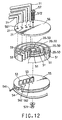
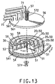
- FIGS 12 and 13 illustrate the sixth embodiment of the present invention, wherein the resistance elements 20 are circular chambers 50 in annular shape and coaxially arranged.
- Each circular chamber 50 comprises two side walls 51, an end cover 59, a rotary disc 55, a fixing plate 56, and a rectangular piston plate 53 which is perpendicularly fixed on the rotary disc 55 and initially located contiguous to the end cover 59.
- the side walls 51 and the end covers 59 are tightly fixed on the fixing plate 56 (they may be also manufactured as a joined single piece).
- a series of air passages 21 and a series of small holes 561 are provided respectively on the same side as the piston plates 53 and on the other side of the end covers 59.
- the small holes 562 may be disposed on the rotary disc 55 and adjacent to the piston plates 53 on the opposite side to the end covers 59, replacing or cooperating with the small holes 561.
- the functions of the small holes 561, 562 and of the air passages 21 which are hermetically connected to the extension tubes 71, have been described hereinbefore, please refer to the description of the first embodiment.
- the rotary disc 55 With the piston plates 53 being sealingly inserted into the circular chambers 50, the rotary disc 55 is sealingly and revolvably secured to the side walls 51, end covers 59 and fixing plate 56 combined by a bolt 57, a spring 572 and a nut 571.
- the rotary disc 55 and the fixing plate 56 also act respectively as the force transmission means 80 and the fixing means 85.
- the rotary disc 55 can be drawn to revolve by a wire 54 connected to and wound on its periphery, thereby moves the piston plates 53 away from the end covers 59, forming and expanding a vacuum chamber 30 therein between.
- the mechanism of gaining a desired resistance is the same as described hereinbefore.
Landscapes
- Health & Medical Sciences (AREA)
- Orthopedic Medicine & Surgery (AREA)
- General Health & Medical Sciences (AREA)
- Physical Education & Sports Medicine (AREA)
- Life Sciences & Earth Sciences (AREA)
- Biophysics (AREA)
- Prostheses (AREA)
- Electrical Discharge Machining, Electrochemical Machining, And Combined Machining (AREA)
- Coupling Device And Connection With Printed Circuit (AREA)
- Filters And Equalizers (AREA)
- Networks Using Active Elements (AREA)
- Adjustable Resistors (AREA)
Abstract
Description
- For an exercising apparatus using atmospheric pressure (i.e. vacuum means) as the source of resisting force, the major advantage is to reduce the total weight of the apparatus compared to an apparatus using gravity force (e.g., weight stacks) as the source of resisting force.
- For example, such apparatus like U.S. Pat. No. 5,336,150, "Lever Resistance Selection Mechanism for Strength Training" and U.K. Pat. GB2267224, "Exercising Device" reveal solutions for adjusting the resistance. Although U.S. Pat. 5,336,150 and GB2267224 disclose several types of resistance adjusting means, none of these resistance adjusting means can allow a user to adjust the level of resistance with a quick and easy process.
- Resistance devices for exercising apparatus are also disclosed in US Pat. No. 5558190 and US Pat. No. 5626543. In each device just one resistance element is provided comprising a chamber of variable volume having valve means by which air flow into and out of the chamber from and to ambient atmosphere is controlled so as to regulate the resisting force offered by the resistance element in exercising operation by a user.
- An object of the present invention is to provide a resistance device which uses atmospheric pressure as the source of resisting force and with resistance adjusting means which can easily adjust the level of resisting force.
- The present invention consists in a resistance device adapted for installation in an exercising apparatus to provide a resisting force from atmospheric pressure, comprising a resistance element having a vacuum chamber that can be increased or reduced in volume and an air passage connected to the vacuum chamber, and moveable force transmission means connected to the resistance element through which a user can impart an exercising force to the resistance element, characterised in that there is a plurality of the resistance elements, the force transmission means is connected to each of the resistance elements, and in that resistance adjusting means is operable to selectively open and/or close one or more of the air passages of the resistance elements such that when the air passage of any one of the resistance elements is closed the respective vacuum chamber is substantially isolated from the atmosphere, and when the air passage of any one of the resistance elements is opened the respective vacuum chamber communicates with the atmosphere and the corresponding resistance element is disabled, the resistance adjusting means being arranged such that resistance to motion of the force transmission means is controllable by adjusting the number of the vacuum chambers open to the atmosphere, while the or each remaining chamber remains isolated from the atmosphere to provide resistance to motion of the force transmission means.
- Each resistance element may be designed to provide an amount of resisting force different to that of another. By arranging different combinations of enabled resistance elements for selection, it is possible to provide more levels of resistance than the number of resistance elements.
- A further object of the present invention is to provide resistance adjusting means which not only can adjust the level of resisting force but also can be used to release (disable) the resistance.
- Another object of the present invention is to use a few resistance elements to achieve many different levels of resistance. For example, four resistance elements may each provide 10Kg, 20Kg, 40Kg, and 80 Kg resistance force. By controlling the enabled or disabled status of these four resistance elements, fifteen different levels (10Kg, 20Kg, .... 150Kg, each level has 10Kg difference ) of resistance can be provided. For example a 130Kg resistance is provided by three enabled resistance elements, 10Kg, 40Kg, and 80 Kg, and one disabled resistance element, 20Kg.
- Other advantages of the present invention will become apparent the course of the following description.
-
- FIG. 1 is an elevational view of the first embodiment of the present invention applied in an exercising apparatus.
- FIG. 2A is an exploded view of the first embodiment regarding the resistance elements of the present invention.
- FIG. 2B is an enlarged cross-section of the one-way valve described in the first embodiment of the present invention.'
- FIG. 3 is an exploded view of a preferred embodiment of the resistance adjusting means of the present invention.
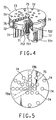
- FIG. 4 is a cutaway view of FIG. 3.
- FIG. 5 is a top plain view of FIG. 3.
- FIG. 6 is an exploded view of the second embodiment regarding the resistance elements of the present invention.
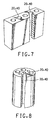
- FIG. 7 illustrates a way in which the cylinder walls in FIG. 2A can be combined as a single piece.
- FIG. 8 illustrates a way. in which the cylinder walls in FIG. 6 can be combined as a single piece.
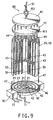
- FIG. 9 is a cutaway view of the third embodiment regarding the resistance elements of the present invention.
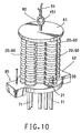
- FIG. 10 is a perspective view of the fourth embodiment regarding the resistance elements of the present invention.
- FIG. 11 is a cutaway view of the fifth embodiment regarding the resistance elements of the present invention.
- FIG. 12 is an exploded view of the sixth embodiment regarding the resistance elements of the present invention.
- FIG. 13 is another view of FIG. 12.
-
- The present invention will now be described, by way of example, with reference to the accompanying diagrammatic drawings. FIG. 1 gives a comprehensive illustration of how the present invention. is applied to an
exercising apparatus 90. Theresistance device 10 comprises a plurality ofresistance elements 20, force transmission means 80 and resistance adjusting means 70. Through the force transmission means 80, auser 99 can apply an exercising force to theresistance elements 20 which provide a resisting force. By operating the resistance adjusting means 70, theuser 99 can adjust the total resistance to a desired level. The fixing means 85 fix theresistance device 10 on the exercisingapparatus 90. To let theuser 99 access the resistance adjusting means 70 within a short distance, theextension tubes 71 connect theresistance elements 20 and the resistance adjusting means 70. During operation, theuser 99 applies an exercising force to draw theresistance elements 20 through awire 91 and the force transmission means 80. - Referring to FIG. 2A regarding the first embodiment of the present invention, each
resistance element 20 is a cylinder 40 (the cross-section is not limited to a circular shape), which comprises apiston head 43 and apiston rod 44. All thecylinders 40 are mounted on the fixing base 46 (i.e., the fixing means 85) which includes the end covers 42 as a part. Thefixing base 46 is then fastened to the exercisingapparatus 90 bybolts 47. Eachend cover 42 at least has anair passage 21 to which anextension tube 71 is hermetically connected. At the top end of eachcylinder 40 is fastened atop cover 41 and all thetop covers 41 are combined together. Eachtop cover 41 has an axial throughhole 412. Thepiston rods 44 extend from thepiston heads 43 through the throughholes 412 and are fixed to a pulling member 45 (i.e. force transmission means 80.) The pullingmember 45 is then connected to awire 91 by aneyebolt 451. - The edge of each
piston head 43 sealingly engages the inner wall ofcylinder 40 to resist passage of air in thecylinder 40 so that avacuum chamber 30 is formed between thepiston head 43 and theend cover 42. Further, anair passage 21 is connected with thevacuum chamber 30. Becausesuch cylinders 40 uses atmospheric pressure as the source of resisting force is a prior art (e.g. U.S. Pat 5,336,150), the theory and detail description will not be discussed hereafter. The amount of resisting force provided by acylinder 40 is depended on the cross-sectional area (F=P*A). - Referring now to FIGS 3, 4 and 5, in a preferred embodiment, the resistance adjusting means 70 mainly comprise a
valve seat 72 and avalve cap 73. Abolt 75 is sequentially inserted through the axle holes 731, 721 and aspring 752 and then screws in anut 751, to revolvably secure thevalve cap 73 onto thevalve seat 72. A plurality ofprotrusions 722 anddepressions 732 are provided respectively on the surface of thevalve seat 72 and on the corresponding positions on thevalve cap 73, so that the user can turn thevalve cap 73 stepwise. Of course, theprotrusions 722 anddepressions 732 may be provided at other appropriate portions of thevalve seat 72 andvalve cap 73 respectively or vice versa. The resistance adjusting means 70 is mounted on the exercisingapparatus 90 through a connectingarm 77 by fasteningmember 771. - The purpose of the resistance adjusting means 70 is to selectively close or open the
air passages 21 of theresistance elements 20. The mechanism will be described hereafter. Thevalve seat 72 comprises a plurality ofair gateways 76 which are respectively hermetically connected to theair passage 21 of thevacuum chambers 30 byextension tubes 71. Thevalve cap 73 comprises a plurality of valve sets 79 and each of valve sets 79 represents a level of resistance. Each valve set 79 is preferably provided with a unique combination ofopenings 74 which are respectively located opposed to the associatedgateways 76 of thevalve seat 72 when this valve set 79 connects to thegateways 76. All theopenings 74 can communicate with the atmosphere. A valve set 79 may be provided with noopening 74, like valve set 79a illustrated in FIG. 5. So if valve set 79a is switched to connect to 10 thegateways 76, theair passages 21 of all theresistance elements 20 are closed, which means that all theresistance elements 20 are enabled and the total resistance is the aggregate of that provided by everyresistance element 20. For another instance, when the valve set 79b which has two middle openings, is switched to connect to thegateways 76, tworesistance elements 20 associated to these openings are disabled because thevacuum chambers 30 of these tworesistance elements 20 communicate with the atmosphere. Therefore, the total resistance provided by selecting valve set 79b is smaller than by selecting valve set 79a. Of course, the resistance adjusting means 70 may be of other forms, for example, solenoid valves combined with an electric circuit to control the open or close status ofair passages 21. - Also referring to FIG. 2A again, each
top cover 41 may have somesmall holes 411 to prevent the outside air quickly flowing into thecylinder 40. Therefore, when auser 99 releases his/her force after the piston heads 43 have been pulled up, the piston heads 43 will not quickly drop down to injure theuser 99. With the design of somesmall holes 411, the top covers 41 should further have one-way valves 48 so that when auser 99 pull up thepiston head 43, the exhaust air can pass through the one-way valves 48 easily. FIG. 2B is a cross-section of atypical one-way valve 48 which consists of acap 481 andopenings 482. - Referring to FIG. 6, the second embodiment of the present invention, the
resistance elements 20 are arranged symmetrically in pairs except the one in the center. Bothresistance elements 20 of a pair (for example, 20a and 20b) are identical and set to be enabled or disabled simultaneously by the resistance adjusting means 70. Therefore, all the resisting forces provided by theresistance elements 20 are balanced during operation without any torque. - FIGS 7 and 8 shows that the
cylinders 40 corresponding FIGS 2A and 6 may be also manufactured as a joined single piece. - Referring to FIG. 9, in a third embodiment of the present invention, the
cylinders 40 are arranged coaxially, in which case at least twopiston rod 44 must be provided for eachpiston head 43 except the one in the center. - Referring to FIG. 10, in the fourth embodiment of the present invention, each
resistance element 20 is a flexible, variable length bellows-like sidewall 60 with two end covers 61, 62. The inside of bellows-like sidewall 60 is avacuum chamber 30 with a variable volume. The prior art of bellows-like vacuum resistance device has been disclosed in U.S. Pat. Nos., 3,884,463 and 5,356,361. Theend cover resistance elements 20, also act respectively as the force transmission means 80 and the fixing means 85. FIG. 11 shows a variation of the fourth embodiment, wherein the flexible side walls 60 are arranged coaxially. - FIGS 12 and 13 illustrate the sixth embodiment of the present invention, wherein the
resistance elements 20 are circular chambers 50 in annular shape and coaxially arranged. Each circular chamber 50 comprises twoside walls 51, anend cover 59, arotary disc 55, a fixingplate 56, and arectangular piston plate 53 which is perpendicularly fixed on therotary disc 55 and initially located contiguous to theend cover 59. Theside walls 51 and the end covers 59 are tightly fixed on the fixing plate 56 (they may be also manufactured as a joined single piece). On the fixingplate 56 and adjacent to the end covers 59, a series ofair passages 21 and a series ofsmall holes 561 are provided respectively on the same side as thepiston plates 53 and on the other side of the end covers 59. Thesmall holes 562 may be disposed on therotary disc 55 and adjacent to thepiston plates 53 on the opposite side to the end covers 59, replacing or cooperating with thesmall holes 561. The functions of thesmall holes air passages 21 which are hermetically connected to theextension tubes 71, have been described hereinbefore, please refer to the description of the first embodiment. - With the
piston plates 53 being sealingly inserted into the circular chambers 50, therotary disc 55 is sealingly and revolvably secured to theside walls 51, end covers 59 and fixingplate 56 combined by abolt 57, aspring 572 and anut 571. Therotary disc 55 and the fixingplate 56 also act respectively as the force transmission means 80 and the fixing means 85. Therotary disc 55 can be drawn to revolve by awire 54 connected to and wound on its periphery, thereby moves thepiston plates 53 away from the end covers 59, forming and expanding avacuum chamber 30 therein between. The mechanism of gaining a desired resistance is the same as described hereinbefore.
Claims (7)
- A resistance device (10) adapted for installation in an exercising apparatus to provide a resisting force from atmospheric pressure, comprising a resistance element (20) having a vacuum chamber (30) that can be increased or reduced in volume and an air passage (21) connected to the vacuum chamber (30), and moveable force transmission means (80) connected to the resistance element (20) through which a user can impart an exercising force to the resistance element (20), characterised in that there is a plurality of the resistance elements (20), the force transmission means (80) is connected to each of the resistance elements (20), and in that resistance adjusting means (70) is operable to selectively open and/or close one or more of the air passages (21) of the resistance elements (20) such that when the air passage (21) of any one of the resistance elements (20) is closed the respective vacuum chamber (30) is substantially isolated from the atmosphere, and when the air passage (21) of any one of the resistance elements (20) is opened the respective vacuum chamber (30) communicates with the atmosphere and the corresponding resistance element (20) is disabled, the resistance adjusting means (70) being arranged such that resistance to motion of the force transmission means (80) is controllable by adjusting the number of the vacuum chambers (30) open to the atmosphere, while the or each remaining chamber (30) remains isolated from the atmosphere to provide resistance to motion of the force transmission means (80).
- A resistance device (10) according to claim 1, characterised in that each resistance element (20) is a cylinder (40) with a piston head (43) and piston rod (44).
- A resistance device (10) according to claim 1, characterised in that the resistance elements (20) are circular chambers of annular shape and co-axially arranged; each circular chamber (50) comprising two side walls (51), an end cover (59), a rotary disc (55), a fixing plate (56), and a rectangular piston plate (53) which is perpendicularly fixed on the rotary disc (55) and initially located contiguous to the end cover (59); and the vacuum chamber (30) is formed between the piston plate (53) and the end cover (59), so that when the user rotates the rotary disc (55) to expand the vacuum chamber (30), the user receives a resisting force from atmospheric pressure.
- A resistance device (10) according to claim 1, characterised in that each resistance element (20) includes a flexible, variable length bellows-like sidewall (60).
- A resistance device (10) according to any of claims 1 to 4, characterised in that the resistance adjusting means (70) further includes a plurality of extension tubes (71) which connect the resistance adjusting means (70) and the air passages (21) of the vacuum chambers (30), so that the distance between the resistance adjusting means (70) and the resistance elements (20) can be extended.
- A resistance device (10) according to any of claims 1 to 5, characterised in that the resistance adjusting means (70) comprises:(1) a valve seat (72), which comprises a plurality of air gateways (76) hermetically connected to respective air passages (21) of the resistance elements (20); and(2) a valve cap (73), which is shiftable with regard to the valve seat (72) and comprising a plurality of valve sets (79), wherein each valve set (79) comprises a combination of openings (74) that may be placed in communication with the atmosphere, and the valve cap (73) being moveable for selecting particular air gateways (76) to be connected with the openings (74) thereby to render the corresponding resistance element (20) open to the atmosphere and unable to resist motions of the force transmission means (80).
- A resistance device (10) according to claim 2, characterised in that the cylinders (40) of the resistance elements (20) are arranged co-axially.
Priority Applications (6)
| Application Number | Priority Date | Filing Date | Title |
|---|---|---|---|
| PT98310103T PT1008368E (en) | 1998-12-09 | 1998-12-09 | RESISTANCE DEVICE |
| DE69807709T DE69807709T2 (en) | 1998-12-09 | 1998-12-09 | resistance device |
| ES98310103T ES2185121T3 (en) | 1998-12-09 | 1998-12-09 | RESISTANCE DEVICE. |
| AT98310103T ATE223246T1 (en) | 1998-12-09 | 1998-12-09 | RESISTANCE DEVICE |
| EP98310103A EP1008368B1 (en) | 1998-12-09 | 1998-12-09 | Resistance device |
| CA002258062A CA2258062C (en) | 1998-12-09 | 1998-12-30 | Resistance device |
Applications Claiming Priority (2)
| Application Number | Priority Date | Filing Date | Title |
|---|---|---|---|
| EP98310103A EP1008368B1 (en) | 1998-12-09 | 1998-12-09 | Resistance device |
| CA002258062A CA2258062C (en) | 1998-12-09 | 1998-12-30 | Resistance device |
Publications (2)
| Publication Number | Publication Date |
|---|---|
| EP1008368A1 EP1008368A1 (en) | 2000-06-14 |
| EP1008368B1 true EP1008368B1 (en) | 2002-09-04 |
Family
ID=32070424
Family Applications (1)
| Application Number | Title | Priority Date | Filing Date |
|---|---|---|---|
| EP98310103A Expired - Lifetime EP1008368B1 (en) | 1998-12-09 | 1998-12-09 | Resistance device |
Country Status (6)
| Country | Link |
|---|---|
| EP (1) | EP1008368B1 (en) |
| AT (1) | ATE223246T1 (en) |
| CA (1) | CA2258062C (en) |
| DE (1) | DE69807709T2 (en) |
| ES (1) | ES2185121T3 (en) |
| PT (1) | PT1008368E (en) |
Family Cites Families (3)
| Publication number | Priority date | Publication date | Assignee | Title |
|---|---|---|---|---|
| US5496242A (en) * | 1994-01-21 | 1996-03-05 | Greenmaster Industrial Corp. | Pull-up exercising machine with safety air buffer |
| US5558190A (en) * | 1995-10-06 | 1996-09-24 | Chang; John | Damping device adapted for use in exercise apparatus |
| US5626543A (en) * | 1996-04-03 | 1997-05-06 | Chen; Ping | Bellows-like exerciser |
-
1998
- 1998-12-09 DE DE69807709T patent/DE69807709T2/en not_active Expired - Lifetime
- 1998-12-09 AT AT98310103T patent/ATE223246T1/en active
- 1998-12-09 ES ES98310103T patent/ES2185121T3/en not_active Expired - Lifetime
- 1998-12-09 PT PT98310103T patent/PT1008368E/en unknown
- 1998-12-09 EP EP98310103A patent/EP1008368B1/en not_active Expired - Lifetime
- 1998-12-30 CA CA002258062A patent/CA2258062C/en not_active Expired - Fee Related
Also Published As
| Publication number | Publication date |
|---|---|
| ATE223246T1 (en) | 2002-09-15 |
| CA2258062A1 (en) | 2000-06-30 |
| CA2258062C (en) | 2004-12-21 |
| DE69807709T2 (en) | 2003-05-15 |
| DE69807709D1 (en) | 2002-10-10 |
| ES2185121T3 (en) | 2003-04-16 |
| PT1008368E (en) | 2003-01-31 |
| EP1008368A1 (en) | 2000-06-14 |
Similar Documents
| Publication | Publication Date | Title |
|---|---|---|
| US6095955A (en) | Resistance device | |
| EP1446201B1 (en) | Exercise apparatus | |
| US6196952B1 (en) | Adjustable dumbbell | |
| US5558190A (en) | Damping device adapted for use in exercise apparatus | |
| US5441466A (en) | Exercise step with adjustable leg bellows | |
| CA2396489A1 (en) | Saddle-ride type vehicle steering damper apparatus | |
| GB2202756A (en) | Chest expander-type exerciser | |
| KR20150027804A (en) | Hybrid resistance system | |
| IT202000027507A1 (en) | SYSTEM FOR AUTOMATIC ADJUSTMENT OF THE WEIGHT OF A HANDLEBAR. | |
| US20060040803A1 (en) | Exercise device | |
| US4974625A (en) | Four mode pneumatic relay | |
| CA2258062C (en) | Resistance device | |
| AU731540B2 (en) | Resistance device | |
| JP2819361B2 (en) | Arm type training device | |
| US4601467A (en) | Valve module and apparatus therefor | |
| US20230113430A1 (en) | Adjustable exercise device | |
| US20150198238A1 (en) | Shifter assembly | |
| CN1255391A (en) | Strain-resistant of sports equipment | |
| KR20050037271A (en) | Exercise equipment | |
| JPH08501514A (en) | Pressure operated door | |
| JPS6030481Y2 (en) | Cylinder with built-in valve mechanism | |
| KR970002959Y1 (en) | Exercising apparatus | |
| JPH0687773U (en) | Power shifter | |
| KR970002960Y1 (en) | Exercising apparatus | |
| KR20050084707A (en) | A health equipment |
Legal Events
| Date | Code | Title | Description |
|---|---|---|---|
| PUAI | Public reference made under article 153(3) epc to a published international application that has entered the european phase |
Free format text: ORIGINAL CODE: 0009012 |
|
| AK | Designated contracting states |
Kind code of ref document: A1 Designated state(s): AT BE CH DE DK ES FI FR GB GR IE IT LI LU NL PT SE |
|
| AX | Request for extension of the european patent |
Free format text: AL;LT;LV;MK;RO;SI |
|
| 17P | Request for examination filed |
Effective date: 20000710 |
|
| 17Q | First examination report despatched |
Effective date: 20001010 |
|
| AKX | Designation fees paid |
Free format text: AT BE CH CY DE DK ES FI FR GB GR IE IT LI LU MC NL |
|
| RBV | Designated contracting states (corrected) |
Designated state(s): AT BE CH DE DK ES FI FR GB GR IE IT LI LU NL PT SE |
|
| GRAG | Despatch of communication of intention to grant |
Free format text: ORIGINAL CODE: EPIDOS AGRA |
|
| GRAG | Despatch of communication of intention to grant |
Free format text: ORIGINAL CODE: EPIDOS AGRA |
|
| GRAH | Despatch of communication of intention to grant a patent |
Free format text: ORIGINAL CODE: EPIDOS IGRA |
|
| GRAH | Despatch of communication of intention to grant a patent |
Free format text: ORIGINAL CODE: EPIDOS IGRA |
|
| GRAA | (expected) grant |
Free format text: ORIGINAL CODE: 0009210 |
|
| AK | Designated contracting states |
Kind code of ref document: B1 Designated state(s): AT BE CH DE DK ES FI FR GB GR IE IT LI LU NL PT SE |
|
| REF | Corresponds to: |
Ref document number: 223246 Country of ref document: AT Date of ref document: 20020915 Kind code of ref document: T |
|
| REG | Reference to a national code |
Ref country code: GB Ref legal event code: FG4D |
|
| REG | Reference to a national code |
Ref country code: CH Ref legal event code: EP |
|
| REG | Reference to a national code |
Ref country code: IE Ref legal event code: FG4D |
|
| REF | Corresponds to: |
Ref document number: 69807709 Country of ref document: DE Date of ref document: 20021010 |
|
| PG25 | Lapsed in a contracting state [announced via postgrant information from national office to epo] |
Ref country code: SE Free format text: LAPSE BECAUSE OF FAILURE TO SUBMIT A TRANSLATION OF THE DESCRIPTION OR TO PAY THE FEE WITHIN THE PRESCRIBED TIME-LIMIT Effective date: 20021204 Ref country code: DK Free format text: LAPSE BECAUSE OF FAILURE TO SUBMIT A TRANSLATION OF THE DESCRIPTION OR TO PAY THE FEE WITHIN THE PRESCRIBED TIME-LIMIT Effective date: 20021204 |
|
| PG25 | Lapsed in a contracting state [announced via postgrant information from national office to epo] |
Ref country code: LU Free format text: LAPSE BECAUSE OF NON-PAYMENT OF DUE FEES Effective date: 20021209 |
|
| REG | Reference to a national code |
Ref country code: GR Ref legal event code: EP Ref document number: 20020403999 Country of ref document: GR |
|
| REG | Reference to a national code |
Ref country code: PT Ref legal event code: SC4A Free format text: AVAILABILITY OF NATIONAL TRANSLATION Effective date: 20021120 |
|
| ET | Fr: translation filed | ||
| REG | Reference to a national code |
Ref country code: ES Ref legal event code: FG2A Ref document number: 2185121 Country of ref document: ES Kind code of ref document: T3 |
|
| PLBE | No opposition filed within time limit |
Free format text: ORIGINAL CODE: 0009261 |
|
| STAA | Information on the status of an ep patent application or granted ep patent |
Free format text: STATUS: NO OPPOSITION FILED WITHIN TIME LIMIT |
|
| 26N | No opposition filed |
Effective date: 20030605 |
|
| PGFP | Annual fee paid to national office [announced via postgrant information from national office to epo] |
Ref country code: FI Payment date: 20041129 Year of fee payment: 7 |
|
| PG25 | Lapsed in a contracting state [announced via postgrant information from national office to epo] |
Ref country code: FI Free format text: LAPSE BECAUSE OF NON-PAYMENT OF DUE FEES Effective date: 20051209 |
|
| PGFP | Annual fee paid to national office [announced via postgrant information from national office to epo] |
Ref country code: PT Payment date: 20080211 Year of fee payment: 10 Ref country code: GR Payment date: 20071219 Year of fee payment: 10 |
|
| REG | Reference to a national code |
Ref country code: PT Ref legal event code: MM4A Free format text: LAPSE DUE TO NON-PAYMENT OF FEES Effective date: 20090609 |
|
| PG25 | Lapsed in a contracting state [announced via postgrant information from national office to epo] |
Ref country code: PT Free format text: LAPSE BECAUSE OF NON-PAYMENT OF DUE FEES Effective date: 20090609 |
|
| PG25 | Lapsed in a contracting state [announced via postgrant information from national office to epo] |
Ref country code: GR Free format text: LAPSE BECAUSE OF NON-PAYMENT OF DUE FEES Effective date: 20090703 |
|
| PGFP | Annual fee paid to national office [announced via postgrant information from national office to epo] |
Ref country code: IE Payment date: 20101223 Year of fee payment: 13 Ref country code: AT Payment date: 20101230 Year of fee payment: 13 |
|
| REG | Reference to a national code |
Ref country code: IE Ref legal event code: MM4A |
|
| PG25 | Lapsed in a contracting state [announced via postgrant information from national office to epo] |
Ref country code: IE Free format text: LAPSE BECAUSE OF NON-PAYMENT OF DUE FEES Effective date: 20111209 |
|
| REG | Reference to a national code |
Ref country code: AT Ref legal event code: MM01 Ref document number: 223246 Country of ref document: AT Kind code of ref document: T Effective date: 20111209 |
|
| PG25 | Lapsed in a contracting state [announced via postgrant information from national office to epo] |
Ref country code: AT Free format text: LAPSE BECAUSE OF NON-PAYMENT OF DUE FEES Effective date: 20111209 |
|
| PGFP | Annual fee paid to national office [announced via postgrant information from national office to epo] |
Ref country code: CH Payment date: 20131219 Year of fee payment: 16 |
|
| PGFP | Annual fee paid to national office [announced via postgrant information from national office to epo] |
Ref country code: IT Payment date: 20131224 Year of fee payment: 16 Ref country code: NL Payment date: 20131219 Year of fee payment: 16 Ref country code: ES Payment date: 20131227 Year of fee payment: 16 |
|
| PGFP | Annual fee paid to national office [announced via postgrant information from national office to epo] |
Ref country code: BE Payment date: 20131227 Year of fee payment: 16 |
|
| PGFP | Annual fee paid to national office [announced via postgrant information from national office to epo] |
Ref country code: GB Payment date: 20141226 Year of fee payment: 17 |
|
| PGFP | Annual fee paid to national office [announced via postgrant information from national office to epo] |
Ref country code: DE Payment date: 20150213 Year of fee payment: 17 |
|
| PGFP | Annual fee paid to national office [announced via postgrant information from national office to epo] |
Ref country code: FR Payment date: 20141224 Year of fee payment: 17 |
|
| PG25 | Lapsed in a contracting state [announced via postgrant information from national office to epo] |
Ref country code: BE Free format text: LAPSE BECAUSE OF NON-PAYMENT OF DUE FEES Effective date: 20141231 |
|
| REG | Reference to a national code |
Ref country code: NL Ref legal event code: V1 Effective date: 20150701 |
|
| REG | Reference to a national code |
Ref country code: NL Ref legal event code: V1 Effective date: 20150701 |
|
| REG | Reference to a national code |
Ref country code: CH Ref legal event code: PL |
|
| PG25 | Lapsed in a contracting state [announced via postgrant information from national office to epo] |
Ref country code: NL Free format text: LAPSE BECAUSE OF NON-PAYMENT OF DUE FEES Effective date: 20150701 |
|
| PG25 | Lapsed in a contracting state [announced via postgrant information from national office to epo] |
Ref country code: LI Free format text: LAPSE BECAUSE OF NON-PAYMENT OF DUE FEES Effective date: 20141231 Ref country code: CH Free format text: LAPSE BECAUSE OF NON-PAYMENT OF DUE FEES Effective date: 20141231 |
|
| PG25 | Lapsed in a contracting state [announced via postgrant information from national office to epo] |
Ref country code: IT Free format text: LAPSE BECAUSE OF NON-PAYMENT OF DUE FEES Effective date: 20141209 |
|
| REG | Reference to a national code |
Ref country code: ES Ref legal event code: FD2A Effective date: 20160127 |
|
| PG25 | Lapsed in a contracting state [announced via postgrant information from national office to epo] |
Ref country code: ES Free format text: LAPSE BECAUSE OF NON-PAYMENT OF DUE FEES Effective date: 20141210 |
|
| REG | Reference to a national code |
Ref country code: DE Ref legal event code: R119 Ref document number: 69807709 Country of ref document: DE |
|
| GBPC | Gb: european patent ceased through non-payment of renewal fee |
Effective date: 20151209 |
|
| REG | Reference to a national code |
Ref country code: FR Ref legal event code: ST Effective date: 20160831 |
|
| PG25 | Lapsed in a contracting state [announced via postgrant information from national office to epo] |
Ref country code: DE Free format text: LAPSE BECAUSE OF NON-PAYMENT OF DUE FEES Effective date: 20160701 Ref country code: GB Free format text: LAPSE BECAUSE OF NON-PAYMENT OF DUE FEES Effective date: 20151209 |
|
| PG25 | Lapsed in a contracting state [announced via postgrant information from national office to epo] |
Ref country code: FR Free format text: LAPSE BECAUSE OF NON-PAYMENT OF DUE FEES Effective date: 20151231 |