EP1007893B1 - Heat exchanger turbulizers with interrupted convolutions - Google Patents
Heat exchanger turbulizers with interrupted convolutions Download PDFInfo
- Publication number
- EP1007893B1 EP1007893B1 EP98941187A EP98941187A EP1007893B1 EP 1007893 B1 EP1007893 B1 EP 1007893B1 EP 98941187 A EP98941187 A EP 98941187A EP 98941187 A EP98941187 A EP 98941187A EP 1007893 B1 EP1007893 B1 EP 1007893B1
- Authority
- EP
- European Patent Office
- Prior art keywords
- convolutions
- turbulizer
- rows
- heat exchanger
- turbulizers
- Prior art date
- Legal status (The legal status is an assumption and is not a legal conclusion. Google has not performed a legal analysis and makes no representation as to the accuracy of the status listed.)
- Expired - Lifetime
Links
- 238000011084 recovery Methods 0.000 claims abstract description 22
- 230000007935 neutral effect Effects 0.000 claims abstract description 17
- 238000012546 transfer Methods 0.000 abstract description 9
- 229910052751 metal Inorganic materials 0.000 abstract description 3
- 239000002184 metal Substances 0.000 abstract description 3
- 239000000463 material Substances 0.000 description 7
- 239000012530 fluid Substances 0.000 description 5
- 229910052782 aluminium Inorganic materials 0.000 description 2
- XAGFODPZIPBFFR-UHFFFAOYSA-N aluminium Chemical compound [Al] XAGFODPZIPBFFR-UHFFFAOYSA-N 0.000 description 2
- 238000004891 communication Methods 0.000 description 2
- 238000004519 manufacturing process Methods 0.000 description 2
- 238000012986 modification Methods 0.000 description 2
- 230000004048 modification Effects 0.000 description 2
- 238000001816 cooling Methods 0.000 description 1
- 238000013461 design Methods 0.000 description 1
- 239000007788 liquid Substances 0.000 description 1
- 238000012423 maintenance Methods 0.000 description 1
- 230000002093 peripheral effect Effects 0.000 description 1
- 230000001737 promoting effect Effects 0.000 description 1
Images



Classifications
-
- F—MECHANICAL ENGINEERING; LIGHTING; HEATING; WEAPONS; BLASTING
- F28—HEAT EXCHANGE IN GENERAL
- F28F—DETAILS OF HEAT-EXCHANGE AND HEAT-TRANSFER APPARATUS, OF GENERAL APPLICATION
- F28F13/00—Arrangements for modifying heat-transfer, e.g. increasing, decreasing
- F28F13/06—Arrangements for modifying heat-transfer, e.g. increasing, decreasing by affecting the pattern of flow of the heat-exchange media
- F28F13/12—Arrangements for modifying heat-transfer, e.g. increasing, decreasing by affecting the pattern of flow of the heat-exchange media by creating turbulence, e.g. by stirring, by increasing the force of circulation
-
- F—MECHANICAL ENGINEERING; LIGHTING; HEATING; WEAPONS; BLASTING
- F28—HEAT EXCHANGE IN GENERAL
- F28D—HEAT-EXCHANGE APPARATUS, NOT PROVIDED FOR IN ANOTHER SUBCLASS, IN WHICH THE HEAT-EXCHANGE MEDIA DO NOT COME INTO DIRECT CONTACT
- F28D1/00—Heat-exchange apparatus having stationary conduit assemblies for one heat-exchange medium only, the media being in contact with different sides of the conduit wall, in which the other heat-exchange medium is a large body of fluid, e.g. domestic or motor car radiators
- F28D1/02—Heat-exchange apparatus having stationary conduit assemblies for one heat-exchange medium only, the media being in contact with different sides of the conduit wall, in which the other heat-exchange medium is a large body of fluid, e.g. domestic or motor car radiators with heat-exchange conduits immersed in the body of fluid
- F28D1/03—Heat-exchange apparatus having stationary conduit assemblies for one heat-exchange medium only, the media being in contact with different sides of the conduit wall, in which the other heat-exchange medium is a large body of fluid, e.g. domestic or motor car radiators with heat-exchange conduits immersed in the body of fluid with plate-like or laminated conduits
- F28D1/0308—Heat-exchange apparatus having stationary conduit assemblies for one heat-exchange medium only, the media being in contact with different sides of the conduit wall, in which the other heat-exchange medium is a large body of fluid, e.g. domestic or motor car radiators with heat-exchange conduits immersed in the body of fluid with plate-like or laminated conduits the conduits being formed by paired plates touching each other
- F28D1/0325—Heat-exchange apparatus having stationary conduit assemblies for one heat-exchange medium only, the media being in contact with different sides of the conduit wall, in which the other heat-exchange medium is a large body of fluid, e.g. domestic or motor car radiators with heat-exchange conduits immersed in the body of fluid with plate-like or laminated conduits the conduits being formed by paired plates touching each other the plates having lateral openings therein for circulation of the heat-exchange medium from one conduit to another
- F28D1/0333—Heat-exchange apparatus having stationary conduit assemblies for one heat-exchange medium only, the media being in contact with different sides of the conduit wall, in which the other heat-exchange medium is a large body of fluid, e.g. domestic or motor car radiators with heat-exchange conduits immersed in the body of fluid with plate-like or laminated conduits the conduits being formed by paired plates touching each other the plates having lateral openings therein for circulation of the heat-exchange medium from one conduit to another the plates having integrated connecting members
-
- F—MECHANICAL ENGINEERING; LIGHTING; HEATING; WEAPONS; BLASTING
- F28—HEAT EXCHANGE IN GENERAL
- F28F—DETAILS OF HEAT-EXCHANGE AND HEAT-TRANSFER APPARATUS, OF GENERAL APPLICATION
- F28F2255/00—Heat exchanger elements made of materials having special features or resulting from particular manufacturing processes
- F28F2255/12—Heat exchanger elements made of materials having special features or resulting from particular manufacturing processes expanded or perforated metal plate
Definitions
- the present invention relates to heat exchangers and to turbulizers for heat exchangers.
- turbulizers located in the tubes or between the plates inside the plate pairs to enhance heat transfer, especially where a liquid, such as oil, passes through these flow passages.
- turbulizers are commonly in the form of expanded metal inserts and they have undulations or convolutions formed therein to create turbulence in the flow and in this way increase heat transfer in the heat exchanger.
- EP-A-203458 discloses turbulizers for heat exchangers having the features of the preamble of enclosed claim 1: a difficulty with the turbulizers described in this patent is that the non-convoluted areas of the turbulizers are too large with respect to the row of convolutions, so the heat transfer efficiency is too low.
- the object of the present invention is to improve the balance between the heat exchange efficiency and flow resistance with respect to the known turbulizer.
- a turbulizer for a heat exchanger including a planar member having a plurality of longitudinal parallel rows of convolutions formed therein characterized by said convolutions being interrupted to form longitudinal neutral channels only between some of the adjacent longitudinal rows of convolutions.
- the convolutions are periodically interrupted in the turbulizer to form non-convoluted neutral channels located between groups of adjacent longitudinal rows of convolutions. Surprisingly, this substantially reduces the pressure drop caused by the turbulizer without appreciably reducing heat transfer.
- a heat exchanger comprising a plurality of spaced-apart tube members defining flow passages there between; said tube members defining spaced-apart inlet and outlet openings; and a turbulizer as previously defined and located in at least one of the flow passages between the respective inlet and outlet openings.
- Heat exchanger 10 is formed of a plurality of spaced-apart tube members or plate pairs 12, each having an upper plate 14, a lower plate 16 and a turbulizer 18 located therebetween. Plates 14, 16 are arranged back-to-back and have joined peripheral edges 20. Plates 14, 16 also have raised central portions 22 which define a flow passage therebetween in which turbulizers 18 are located. Raised central portions 22 also define spaced-apart inlet and outlet openings 24, 26 for the flow of fluid, such as oil, through the plate pairs.
- plates 14, 16 and the fins 28 can be any shape and configuration desired and are not, per se ,considered to be part of the present invention.
- plates 14, 16 can be formed with outwardly disposed dimples which mate in adjacent plate pairs in which case, fins 28 would not be used.
- a turbulizer 30 is shown which could be used as the turbulizer 18 in Figure 1, according to a prior art solution and which is not encompassed by the enclosed claims.
- Figures 5, 8 show preferred embodiments of turbulizers according to the present invention. Any one of these could be used as the turbulizer 18 in the heat exchanger 10 shown in Figure 1.
- the turbulizers shown in Figures 2, 5, 8 are just illustrations of sections or portions of the turbulizers. It will be appreciated that these turbulizers can be made in any length or width desired depending upon the manufacturing method.
- the turbulizers usually are stamped or roll-formed out of aluminum about 0.01 inches (0.25 mm) thick. However, other materials and heavier or thinner materials can be used for the turbulizers as well.
- Turbulizer 30 is a planar member having a plurality of convolutions 32, 34 formed therein. Convolutions 32, 34 are arranged in parallel rows. Where turbulizer 30 is elongate in shape, convolutions 32, 34 are arranged in parallel, longitudinal rows 36, and also in parallel transverse rows 38.
- Convolutions 32, 34 are interrupted periodically to form non-convoluted pressure recovery zones 40 located between or downstream of the convolutions 32, 34 in each row of convolutions 36.
- the convolutions 32, 34 in each row are spaced-apart by pressure recovery zones 40, rather than being located contiguous to one another.
- Turbulizer 30 has a central plane containing pressure recovery zones 40 as indicated by arrow 41 in Figure 3, and convolutions 32, 34 extend alternately above (convolutions 32) and below (convolutions 34) the central plane 41.
- Convolutions 32, 34 are in the form of bridges, and turbulizer 30 has a high pressure drop orientation in the direction of the bridges, or in the longitudinal direction, and a low pressure drop orientation in the direction passing under the bridges or the transverse direction.
- the convolutions 32, 34 are interrupted in the high pressure drop direction by pressure recovery zones 40 located between or downstream of the convolutions.
- the pressure recovery zones 40 are located in transverse rows or neutral channels 41 themselves.
- turbulizer 30 When turbulizer 30 is used as the turbulizer 18 in heat exchanger 10 of Figure 1, fluid flows in the high pressure drop orientation or direction parallel to longitudinal rows 36 from inlet openings 24 to outlet openings 26. The fluid flows around and under or through convolutions 32, 34. This causes turbulence and reduces boundary layer growth increasing the heat transfer coefficient.
- pressure recovery zones 40 allow for a pressure recovery to reduce flow resistance or pressure drop in the fluid passing from inlet openings 24 to outlet openings 26.
- convolutions 32, 34 are aligned in the low pressure drop or transverse direction.
- pressure recovery zones 40 are aligned in the low pressure drop or transverse direction to form neutral channels 41. Pressure recovery zones 40 thus form continuous neutral channels 41 in the low pressure drop direction. These neutral channels 41 also provide areas that can be used to eject the turbulizer from the dies used to produce the turbulizer.
- the width of the convoluted longitudinal rows 36 is preferably as narrow as is practical for tool design and maintenance purposes. For automotive cooling purposes, a preferred minimum width would be about 0.02 inches (0.5 mm). The maximum width should not exceed ten times the minimum. Typically, the maximum width would be about 0.2 inches (5 mm).
- the longitudinal length of pressure recovery zones 40 ranges from about 5% of the longitudinal or centerline to centerline spacing between convolutions 32, 34 to about 75% of the spacing between any two consecutive convolutions 32, 34. A preferable range would be between 0.02 inches (0.5 mm) to about 0.5 inches (1.25 cm), or about 40% to 50% of the centerline to centerline distance between longitudinally consecutive convolutions 32, 34.
- the height of convolutions 32, 34 above or below the central plane 41 containing pressure recovery zones 40 depends upon the thickness of the material used for turbulizer 30. This height should not be less than the material thickness and typically ranges from this minimum to about 10 times the material thickness where aluminum is used for turbulizer 30. A good range is from 0.01 inches (0.25 mm) to 0.5 inches (1.25 cm).
- the longitudinal length of convolutions 32, 34 is normally about 2 times the height of the convolutions.
- the height normally ranges from about 2 times the material thickness to about 20 times the material thickness.
- a good range is from 0.02 inches (0.5 mm) to about 1.0 inch (2.5 cm).
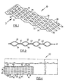
- a turbulizer 55 is shown that is most similar to turbulizer 30 of Figure 2, except the convolutions 32, 34 are also interrupted in the low pressure drop direction to form further pressure recovery zones 56 located between some of the rows of convolutions 36.
- pressure recovery zones 56 extend longitudinally the full length of turbulizer 55 to form longitudinal neutral channels 58 in the high pressure drop or longitudinal direction of turbulizer 55.
- the width of neutral channels 58 preferably is about the same as the width of the rows of convolutions 36.
- the convolutions 32, 34 are aligned in the low pressure drop or transverse direction, but they could be staggered as well.
- turbulizer 55 is similar to turbulizers 30, 45 and 50.
- a turbulizer 60 is shown where the convolutions 32, 34 are interrupted only in the low pressure drop or transverse direction and only between some of the rows of convolutions 36. These interruptions make pressure recovery zones 61 in the form of longitudinal neutral channels 62. In all other respects, turbulizer 60 is similar to turbulizers 30 and 55. In Figures 8 to 10, turbulizer 60 is shown cut to length in the middle of convolutions 32, 34. This has been done for the purposes of illustration. In practice, the turbulizers would normally be cut to length between the convolutions, as is the case in Figures 1 to 7.
- turbulizers 18 would be inserted lengthwise into one end of the tubes.
- the convolutions 32, 34 have been shown to be rounded with various curvatures. These convolutions can be any configuration, such as semi-circular, sinusoidal, trapezoidal or even V-shaped, if desired.
- turbulizer 18 is shown to be orientated such that the flow is in the high pressure drop or longitudinal direction.
- the turbulizer could be rotated 90 degrees so that the flow from inlet 24 to outlet 26 is in the low pressure drop direction if desired. It will also be appreciated that the various features of turbulizers 30, 55 and 60 could be mixed and matched, or a combination of these features could be employed in the same turbulizer. Also, any given heat exchanger could have any one or a combination of the turbulizers described above. Other modifications to the structure described above will be apparent to those skilled in the art.
Landscapes
- Engineering & Computer Science (AREA)
- Physics & Mathematics (AREA)
- Thermal Sciences (AREA)
- Mechanical Engineering (AREA)
- General Engineering & Computer Science (AREA)
- Heat-Exchange Devices With Radiators And Conduit Assemblies (AREA)
Abstract
Description
Claims (10)
- A turbulizer for a heat exchanger, the turbulizer including a planar member having a plurality of longitudinal parallel rows (36) of convolutions (32, 34) formed therein characterized by said convolutions (32, 34) being interrupted to form longitudinal neutral channels (58; 62) only between some of the adjacent longitudinal rows (36) of convolutions.
- A turbulizer as claimed in claim 1, characterized in that the convolutions (32, 34) are in the form of bridges, the bridges being orientated longitudinally to define a high pressure drop orientation in the direction of the bridges and a low pressure drop orientation transversely in the direction passing under the bridges.
- A turbulizer as claimed in claim 2, characterized in that wherein the rows (36) of convolutions are further interrupted in the longitudinal direction to form pressure recovery zones (40) located longitudinally between the convolutions (32, 34).
- A turbulizer as claimed in claim 3, characterized in that the convolutions (32, 34) are aligned in the transverse direction, the pressure recovery zones (40) also being aligned transversely to form neutral channels (59) in the transverse direction.
- A turbulizer as claimed in claim 2, characterized in that the convolutions (32, 34) are staggered in the transverse direction.
- A turbulizer as claimed in claim 2, characterized in that the convolutions (32, 34) are aligned in the transverse direction.
- A turbulizer as claimed in claim 3, characterized by having a central plane containing the pressure recovery zones, the convolutions (32, 34) in each row (36) of convolutions extending alternately above and below the central plane.
- A turbulizer as claimed in claim 5, characterized by having a central plane containing the pressure recovery zones, the convolutions (32, 34) in each row (26) of convolutions extending alternately above and below the central plane.
- A turbulizer as claimed in claim 1, characterized in that said groups include three rows (36) of convolutions, there being a single longitudinal neutral channel (58; 62) between each group.
- A heat exchanger (10) comprising a plurality of spaced-apart tube members defining flow passages there between; said tube members defining spaced-apart inlet and outlet openings (24, 26); and a turbulizer (55; 60) as claimed in any one of the foregoing claims; said turbulizer (55; 60) being located in at least one of the flow passages between the respective inlet and outlet openings (24, 26).
Applications Claiming Priority (3)
| Application Number | Priority Date | Filing Date | Title |
|---|---|---|---|
| CA002214255A CA2214255C (en) | 1997-08-29 | 1997-08-29 | Heat exchanger turbulizers with interrupted convolutions |
| CA2214255 | 1997-08-29 | ||
| PCT/CA1998/000826 WO1999011995A1 (en) | 1997-08-29 | 1998-08-28 | Heat exchanger turbulizers with interrupted convolutions |
Publications (2)
| Publication Number | Publication Date |
|---|---|
| EP1007893A1 EP1007893A1 (en) | 2000-06-14 |
| EP1007893B1 true EP1007893B1 (en) | 2004-01-02 |
Family
ID=4161363
Family Applications (1)
| Application Number | Title | Priority Date | Filing Date |
|---|---|---|---|
| EP98941187A Expired - Lifetime EP1007893B1 (en) | 1997-08-29 | 1998-08-28 | Heat exchanger turbulizers with interrupted convolutions |
Country Status (12)
| Country | Link |
|---|---|
| EP (1) | EP1007893B1 (en) |
| JP (1) | JP3749436B2 (en) |
| KR (1) | KR100370487B1 (en) |
| AT (2) | AT411397B (en) |
| AU (1) | AU738890B2 (en) |
| BR (1) | BR9811403A (en) |
| CA (1) | CA2214255C (en) |
| DE (2) | DE69820880T2 (en) |
| ES (2) | ES2191524A1 (en) |
| GB (1) | GB2345336B (en) |
| SE (1) | SE517362C2 (en) |
| WO (1) | WO1999011995A1 (en) |
Cited By (1)
| Publication number | Priority date | Publication date | Assignee | Title |
|---|---|---|---|---|
| EP3038743B1 (en) * | 2013-08-30 | 2023-06-07 | Beijing Zehua Chemical Engineering Co., Ltd. | Tower packing element, tower packing, and packing tower and mixer comprising the same |
Families Citing this family (7)
| Publication number | Priority date | Publication date | Assignee | Title |
|---|---|---|---|---|
| CA2420273A1 (en) | 2003-02-27 | 2004-08-27 | Peter Zurawel | Heat exchanger plates and manufacturing method |
| JP2007113821A (en) * | 2005-10-19 | 2007-05-10 | Tokyo Roki Co Ltd | Stacked heat exchanger |
| DE102007036305A1 (en) * | 2007-07-31 | 2009-02-05 | Behr Gmbh & Co. Kg | Heat-dissipating fins complementing coolant tubes in vehicle engine radiator block, have expanded-metal structure and corrugated form |
| KR101354916B1 (en) | 2007-11-02 | 2014-01-22 | 한라비스테온공조 주식회사 | Oil cooler |
| JP2009204182A (en) * | 2008-02-26 | 2009-09-10 | Denso Corp | Heat exchanger |
| DE112012002517T5 (en) * | 2011-06-17 | 2014-02-27 | Lithium Energy Japan | battery assembly |
| KR101423656B1 (en) | 2012-08-24 | 2014-07-25 | 주식회사 한국쿨러 | Exhaust gas heat exchanger |
Family Cites Families (7)
| Publication number | Priority date | Publication date | Assignee | Title |
|---|---|---|---|---|
| FR1537101A (en) * | 1967-07-11 | 1968-08-23 | Chausson Usines Sa | Interference device for heat exchanger duct |
| DE2113583B2 (en) * | 1971-03-20 | 1979-02-22 | Dieter Steinegg Appenzell Steeb (Schweiz) | Heat exchanger with flat tubes arranged parallel to one another and method for manufacturing the heat exchanger |
| JPS5638874B2 (en) * | 1974-05-10 | 1981-09-09 | ||
| CA1046499A (en) * | 1975-01-16 | 1979-01-16 | Borg-Warner Corporation | Air side turbulizer |
| FR2536524A1 (en) * | 1982-11-19 | 1984-05-25 | Nibart Jean Clair | Lining element for heat exchanger and heat exchanger comprising said lining |
| DE3660604D1 (en) * | 1985-05-15 | 1988-09-29 | Showa Aluminum Corp | Heat-exchanger of plate fin type |
| US4815534A (en) * | 1987-09-21 | 1989-03-28 | Itt Standard, Itt Corporation | Plate type heat exchanger |
-
1997
- 1997-08-29 CA CA002214255A patent/CA2214255C/en not_active Expired - Lifetime
-
1998
- 1998-08-28 DE DE1998620880 patent/DE69820880T2/en not_active Expired - Fee Related
- 1998-08-28 KR KR10-2000-7001976A patent/KR100370487B1/en not_active Expired - Fee Related
- 1998-08-28 AU AU89688/98A patent/AU738890B2/en not_active Ceased
- 1998-08-28 DE DE19882638T patent/DE19882638T1/en not_active Ceased
- 1998-08-28 BR BR9811403-4A patent/BR9811403A/en not_active Application Discontinuation
- 1998-08-28 GB GB0003877A patent/GB2345336B/en not_active Revoked
- 1998-08-28 JP JP2000508954A patent/JP3749436B2/en not_active Expired - Lifetime
- 1998-08-28 WO PCT/CA1998/000826 patent/WO1999011995A1/en not_active Ceased
- 1998-08-28 EP EP98941187A patent/EP1007893B1/en not_active Expired - Lifetime
- 1998-08-28 ES ES200050017A patent/ES2191524A1/en active Pending
- 1998-08-28 AT AT0911198A patent/AT411397B/en not_active IP Right Cessation
- 1998-08-28 AT AT98941187T patent/ATE257238T1/en not_active IP Right Cessation
- 1998-08-28 ES ES98941187T patent/ES2212332T3/en not_active Expired - Lifetime
-
2000
- 2000-02-17 SE SE0000511A patent/SE517362C2/en unknown
Cited By (1)
| Publication number | Priority date | Publication date | Assignee | Title |
|---|---|---|---|---|
| EP3038743B1 (en) * | 2013-08-30 | 2023-06-07 | Beijing Zehua Chemical Engineering Co., Ltd. | Tower packing element, tower packing, and packing tower and mixer comprising the same |
Also Published As
| Publication number | Publication date |
|---|---|
| ATE257238T1 (en) | 2004-01-15 |
| EP1007893A1 (en) | 2000-06-14 |
| DE69820880D1 (en) | 2004-02-05 |
| KR20010023338A (en) | 2001-03-26 |
| GB2345336B (en) | 2002-06-05 |
| JP3749436B2 (en) | 2006-03-01 |
| DE69820880T2 (en) | 2004-11-18 |
| JP2001515196A (en) | 2001-09-18 |
| GB2345336A (en) | 2000-07-05 |
| CA2214255A1 (en) | 1999-02-28 |
| SE0000511D0 (en) | 2000-02-17 |
| KR100370487B1 (en) | 2003-02-05 |
| BR9811403A (en) | 2000-08-29 |
| AU8968898A (en) | 1999-03-22 |
| WO1999011995A1 (en) | 1999-03-11 |
| SE0000511L (en) | 2000-02-17 |
| AU738890B2 (en) | 2001-09-27 |
| ATA911198A (en) | 2003-05-15 |
| CA2214255C (en) | 2004-11-02 |
| AT411397B (en) | 2003-12-29 |
| ES2191524A1 (en) | 2003-09-01 |
| GB0003877D0 (en) | 2000-04-05 |
| ES2212332T3 (en) | 2004-07-16 |
| SE517362C2 (en) | 2002-05-28 |
| DE19882638T1 (en) | 2000-08-03 |
Similar Documents
| Publication | Publication Date | Title |
|---|---|---|
| US6273183B1 (en) | Heat exchanger turbulizers with interrupted convolutions | |
| US4665975A (en) | Plate type heat exchanger | |
| CA2050281C (en) | Heat exchangers | |
| US10048020B2 (en) | Heat transfer surfaces with flanged apertures | |
| EP0384316B1 (en) | Embossed plate heat exchanger | |
| US4804041A (en) | Heat-exchanger of plate fin type | |
| CA1064902A (en) | Heat exchange device | |
| US6938685B2 (en) | Heat exchanger | |
| US5318112A (en) | Finned-duct heat exchanger | |
| US4830102A (en) | Turbulent heat exchanger | |
| US4934455A (en) | Plate-fin heat exchanger | |
| JPH01193596A (en) | Plate fin for heat exchanger and plate fin tube type heat exchanger | |
| GB2362456A (en) | Heat exchange fin | |
| US20040144525A1 (en) | Heat exchanger with brazed plates | |
| US20090260789A1 (en) | Heat exchanger with expanded metal turbulizer | |
| EP0415584B1 (en) | Stack type evaporator | |
| KR20010105349A (en) | Heat and mass transfer element assembly | |
| AU738890B2 (en) | Heat exchanger turbulizers with interrupted convolutions | |
| US4434846A (en) | Patterned heat exchanger fin | |
| EP0203458A1 (en) | Heat-exchanger of plate fin type | |
| EP2064509B1 (en) | Heat transfer surfaces with flanged apertures | |
| JPH02634B2 (en) | ||
| CA1239927A (en) | High heat transfer means for flat tube and fin heat exchangers | |
| GB2183811A (en) | Rotary regenerative heat exchanger | |
| US5875839A (en) | Heat exchanger for air conditioner |
Legal Events
| Date | Code | Title | Description |
|---|---|---|---|
| PUAI | Public reference made under article 153(3) epc to a published international application that has entered the european phase |
Free format text: ORIGINAL CODE: 0009012 |
|
| 17P | Request for examination filed |
Effective date: 20000321 |
|
| AK | Designated contracting states |
Kind code of ref document: A1 Designated state(s): AT BE CH CY DE DK ES FI FR GB GR IE IT LI LU MC NL PT SE |
|
| 17Q | First examination report despatched |
Effective date: 20001031 |
|
| GRAH | Despatch of communication of intention to grant a patent |
Free format text: ORIGINAL CODE: EPIDOS IGRA |
|
| RBV | Designated contracting states (corrected) |
Designated state(s): AT DE ES FR GB IT SE |
|
| RAP1 | Party data changed (applicant data changed or rights of an application transferred) |
Owner name: DANA CANADA CORPORATION |
|
| GRAS | Grant fee paid |
Free format text: ORIGINAL CODE: EPIDOSNIGR3 |
|
| GRAA | (expected) grant |
Free format text: ORIGINAL CODE: 0009210 |
|
| AK | Designated contracting states |
Kind code of ref document: B1 Designated state(s): AT DE ES FR GB IT SE |
|
| PG25 | Lapsed in a contracting state [announced via postgrant information from national office to epo] |
Ref country code: AT Free format text: LAPSE BECAUSE OF FAILURE TO SUBMIT A TRANSLATION OF THE DESCRIPTION OR TO PAY THE FEE WITHIN THE PRESCRIBED TIME-LIMIT Effective date: 20040102 |
|
| REG | Reference to a national code |
Ref country code: GB Ref legal event code: FG4D |
|
| REG | Reference to a national code |
Ref country code: IE Ref legal event code: FG4D |
|
| REF | Corresponds to: |
Ref document number: 69820880 Country of ref document: DE Date of ref document: 20040205 Kind code of ref document: P |
|
| PG25 | Lapsed in a contracting state [announced via postgrant information from national office to epo] |
Ref country code: SE Free format text: LAPSE BECAUSE OF FAILURE TO SUBMIT A TRANSLATION OF THE DESCRIPTION OR TO PAY THE FEE WITHIN THE PRESCRIBED TIME-LIMIT Effective date: 20040402 |
|
| REG | Reference to a national code |
Ref country code: ES Ref legal event code: FG2A Ref document number: 2212332 Country of ref document: ES Kind code of ref document: T3 |
|
| ET | Fr: translation filed | ||
| PGFP | Annual fee paid to national office [announced via postgrant information from national office to epo] |
Ref country code: DE Payment date: 20040930 Year of fee payment: 7 |
|
| PLBE | No opposition filed within time limit |
Free format text: ORIGINAL CODE: 0009261 |
|
| STAA | Information on the status of an ep patent application or granted ep patent |
Free format text: STATUS: NO OPPOSITION FILED WITHIN TIME LIMIT |
|
| 26N | No opposition filed |
Effective date: 20041005 |
|
| REG | Reference to a national code |
Ref country code: IE Ref legal event code: MM4A |
|
| PG25 | Lapsed in a contracting state [announced via postgrant information from national office to epo] |
Ref country code: DE Free format text: LAPSE BECAUSE OF NON-PAYMENT OF DUE FEES Effective date: 20060301 |
|
| PGFP | Annual fee paid to national office [announced via postgrant information from national office to epo] |
Ref country code: ES Payment date: 20080826 Year of fee payment: 11 |
|
| PGFP | Annual fee paid to national office [announced via postgrant information from national office to epo] |
Ref country code: IT Payment date: 20090827 Year of fee payment: 12 |
|
| REG | Reference to a national code |
Ref country code: ES Ref legal event code: FD2A Effective date: 20090829 |
|
| PG25 | Lapsed in a contracting state [announced via postgrant information from national office to epo] |
Ref country code: IT Free format text: LAPSE BECAUSE OF NON-PAYMENT OF DUE FEES Effective date: 20100828 |
|
| PG25 | Lapsed in a contracting state [announced via postgrant information from national office to epo] |
Ref country code: ES Free format text: LAPSE BECAUSE OF NON-PAYMENT OF DUE FEES Effective date: 20090829 |
|
| REG | Reference to a national code |
Ref country code: FR Ref legal event code: PLFP Year of fee payment: 18 |
|
| REG | Reference to a national code |
Ref country code: FR Ref legal event code: PLFP Year of fee payment: 19 |
|
| REG | Reference to a national code |
Ref country code: FR Ref legal event code: PLFP Year of fee payment: 20 |
|
| PGFP | Annual fee paid to national office [announced via postgrant information from national office to epo] |
Ref country code: FR Payment date: 20170825 Year of fee payment: 20 Ref country code: GB Payment date: 20170829 Year of fee payment: 20 |
|
| REG | Reference to a national code |
Ref country code: GB Ref legal event code: PE20 Expiry date: 20180827 |
|
| PG25 | Lapsed in a contracting state [announced via postgrant information from national office to epo] |
Ref country code: GB Free format text: LAPSE BECAUSE OF EXPIRATION OF PROTECTION Effective date: 20180827 |