EP1007127B1 - Gas supply apparatus for the supply of treatment gas to a person or to an animal - Google Patents
Gas supply apparatus for the supply of treatment gas to a person or to an animal Download PDFInfo
- Publication number
- EP1007127B1 EP1007127B1 EP98915098A EP98915098A EP1007127B1 EP 1007127 B1 EP1007127 B1 EP 1007127B1 EP 98915098 A EP98915098 A EP 98915098A EP 98915098 A EP98915098 A EP 98915098A EP 1007127 B1 EP1007127 B1 EP 1007127B1
- Authority
- EP
- European Patent Office
- Prior art keywords
- liquid
- emitting device
- gas
- supply
- anaesthetic
- Prior art date
- Legal status (The legal status is an assumption and is not a legal conclusion. Google has not performed a legal analysis and makes no representation as to the accuracy of the status listed.)
- Expired - Lifetime
Links
Images


Classifications
-
- A—HUMAN NECESSITIES
- A61—MEDICAL OR VETERINARY SCIENCE; HYGIENE
- A61M—DEVICES FOR INTRODUCING MEDIA INTO, OR ONTO, THE BODY; DEVICES FOR TRANSDUCING BODY MEDIA OR FOR TAKING MEDIA FROM THE BODY; DEVICES FOR PRODUCING OR ENDING SLEEP OR STUPOR
- A61M16/00—Devices for influencing the respiratory system of patients by gas treatment, e.g. mouth-to-mouth respiration; Tracheal tubes
- A61M16/10—Preparation of respiratory gases or vapours
- A61M16/14—Preparation of respiratory gases or vapours by mixing different fluids, one of them being in a liquid phase
- A61M16/18—Vaporising devices for anaesthetic preparations
-
- A—HUMAN NECESSITIES
- A61—MEDICAL OR VETERINARY SCIENCE; HYGIENE
- A61M—DEVICES FOR INTRODUCING MEDIA INTO, OR ONTO, THE BODY; DEVICES FOR TRANSDUCING BODY MEDIA OR FOR TAKING MEDIA FROM THE BODY; DEVICES FOR PRODUCING OR ENDING SLEEP OR STUPOR
- A61M16/00—Devices for influencing the respiratory system of patients by gas treatment, e.g. mouth-to-mouth respiration; Tracheal tubes
- A61M16/10—Preparation of respiratory gases or vapours
- A61M16/1075—Preparation of respiratory gases or vapours by influencing the temperature
- A61M16/109—Preparation of respiratory gases or vapours by influencing the temperature the humidifying liquid or the beneficial agent
-
- A—HUMAN NECESSITIES
- A61—MEDICAL OR VETERINARY SCIENCE; HYGIENE
- A61M—DEVICES FOR INTRODUCING MEDIA INTO, OR ONTO, THE BODY; DEVICES FOR TRANSDUCING BODY MEDIA OR FOR TAKING MEDIA FROM THE BODY; DEVICES FOR PRODUCING OR ENDING SLEEP OR STUPOR
- A61M16/00—Devices for influencing the respiratory system of patients by gas treatment, e.g. mouth-to-mouth respiration; Tracheal tubes
- A61M16/10—Preparation of respiratory gases or vapours
- A61M16/14—Preparation of respiratory gases or vapours by mixing different fluids, one of them being in a liquid phase
- A61M16/147—Preparation of respiratory gases or vapours by mixing different fluids, one of them being in a liquid phase the respiratory gas not passing through the liquid container
Definitions
- the present invention relates to an apparatus of the kind defined in the preamble of Claim 1.
- An apparatus according to the preamble of claim 1 is known from GB-A-2 255 912.
- the invention can be applied in a number of different applications in respect of supplying treatment gas to human beings and to animals, it finds particularly beneficial use in the anaesthesia of patients, in which case it is intended that the apparatus is connected to the system of hoses and devices by means of which breathing gas is supplied to a patient and to deliver the anaesthetic in a gasified state to the patient concerned.
- Anaesthetic vaporisers are well known to the art, and a large number of different methods have been described. With regard to known and used vaporisers, reference is made to Anaesthetic Equipment, C.S. Ward, published by Bailliere Tindall, 2nd edition, 1987, pp. 78-103 and to Anaesthesia Vaporisers by J.B. Eisenkraft in Anaesthesia Equipment, Principles and Applications, by Jan Ekrenwerth, James B. Eisenkraft, published by Mosby, 1993, pp. 57-58.
- the earlier described vaporisers are based on the principle of storing liquid anaesthetic in a container into which there is introduced a breathing gas which passes over the liquid surface or bubbles through the liquid anaesthetic.
- This problem has been dealt with by delivering additional heat in the case of some designs, or by varying the amount of breathing gas that passes over the liquid surface and then combining different gas flows so as to enable a constant anaesthetic content to be obtained in the breathing gas.
- Vaporisation of the anaesthetic is dependent on the rate of flow of the breathing gas. Attempts to compensate for this dependency have been made by using different intricate flow-dependent valves and gas mixing systems in the vaporiser. The flow dependency can become problematic, particularly in the case of low fresh-gas flows that are used in so-called low flow systems.
- Anaesthetics have different vaporisation characteristics in different gas mixtures. This can result in administering to a patient a different amount of anaesthetic than that for which the vaporiser is set, due to the composition of the gas mixture.
- a number of systems are based on the immersion of a wick in the anaesthetic.
- the anaesthetic is drawn up by the wick and vaporised on its surface.
- the drawback with this system is that the rate at which the anaesthetic is drawn up the wick will depend on the height and temperature of the liquid surface, therewith necessitating the inclusion of a compensatory system in the vaporiser.
- DE-A 4 105 163 teaches a anaesthetic vaporising system in which a porous body throughpassed by anaesthetic gases is saturated with anaesthetic.
- U.S. 3,540,445 describes a vaporiser in which fibrous wicks have been replaced with porous synthetic plastics that absorb the anaesthetic from a container through the medium of capillary forces.
- the container can admittedly be topped-up, the amount of anaesthetic taken up by the passing gas is primarily determined by the evaporation from the porous plastic rods and the capillary forces within these rods (when the level in a vessel filled with anaesthetic is kept constant), and consequently the apparatus becomes temperature-dependent and also dependent on the anaesthetic to be vaporised.
- GB 2 255 912 describes a system that uses porous rods through which the gas passes on the one hand and which are passed by the gas on the other hand. These rods are supplied with gaseous anaesthetic, by submerging the rods in the anaesthetic.
- the level of anaesthetic in relation to the rods is regulated by a level regulator. It is necessary to regulate the rods and the temperature of the anaesthetic and the gas in order to obtain a stable concentration of anaesthetic in the gas.
- GB 2 279 015 describes an apparatus in which the liquid to be vaporised is exposed to the gas, partly through porosities and partly through the free liquid surface, thereby also requiring the provision of temperature control means.
- the apparatus has no liquid quantity control facility.
- the object of the present invention is to eliminate several of the drawbacks of the aforedescribed systems and to provide a method and apparatus that will provide uniform vaporisation of a large number of different anaesthetics in respect of a large number of different gas mixtures and flows.
- the invention is thus based on delivering the liquid to be vaporised actively to the liquid emitting device, and is not therefore encumbered by the drawbacks associated with the type of system in which the vaporiser is charged with an initial quantity of liquid which is consumed during the process and the vaporisation process thereby influenced, i.e. such systems as those exemplified by the first three patent publications mentioned above.
- the invention is based on the same liquid delay principle as that described in the aforementioned publication GB 2 255 912, according to which liquid is delivered constantly to the liquid emitting device from an external liquid source.
- these problems that accompany the construction of this apparatus with the inclusion of porous rods that are partially immersed in a liquid and with the free liquid surface in contact with the bypassing gas, and where the vaporisation process in the rods is sensitive to variations in liquid level have been avoided by means of the special features of the present invention.
- the liquid in the liquid emitting device is exposed solely through its porosities, so as to eliminate the effect of the level of a free liquid surface. Because the liquid is exposed solely via said porosities, the delivery of vaporised medium is determined solely by the delivery rate of the pump.
- there is provided a large and constant exposure surface area so that the rate of evaporation will be at least equal to the liquid-emitting rate and can also be controlled, regulated, in a sure and purposeful manner.
- the facility of enabling the liquid to be heated with the aid of the heating device enables the temperature of the liquid to be adapted in relation to the nature of liquid to be vaporised, so as to obtain optimum conditions with regard to the vaporisation process.
- the heating device is placed within the liquid-emitting device, therewith providing effective heating.
- the heating device is placed outside but adjacent to the liquid-emitting device, therewith enabling the components to be arranged simply.
- One quick and simple method of heating the liquid is to use a heating device in the form of an electric resistance, this embodiment comprising a further preferred embodiment of the invention.
- the liquid-emitting devices can be controlled so as to adapt readily to variations in requirements, for instance in response to different types of liquid to be vaporised.
- the liquid is delivered by means of a pump, preferably a motor-driven pump, so as to provide safe and uniform supply of liquid and to enable the liquid supply to be readily regulated.
- the concentration of vaporised liquid in the outgoing air is preferably sensed by an optical sensor which appropriately controls the regulation of the amount of liquid supplied.
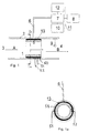
- the apparatus illustrated in Fig. 1 includes a vaporising chamber 1 formed by a container 2. Although the container is shown to have a tubular shape it will be understood that it may have any other desired shape.
- the vaporisation chamber 1 has an inlet opening 3 which is connected to a gas delivery inlet line (not shown) as symbolised with the arrow A, and an outlet opening 4 which is connected to a gas discharge outlet line (not shown), symbolised with the arrow B.
- the outlet line is intended for connection with the respiratory organs of a patient for the delivery of, in this case, anaesthetic gas.
- a liquid-emitting device 5 Arranged in the vaporisation chamber 1 is a liquid-emitting device 5 in the form of a porous body.
- the porous body has a cylindrical shape and is conveniently made of plastic material.
- a delivery line 6 for the delivery of anaesthetic in liquid form is connected to the liquid-emitting device 5.
- the gas flows from the inlet 3 and through the chamber 1 to the outlet 4, it passes the liquid-emitting device 5 and comes into contact with the liquid present in the porosities of said device. As the liquid is exposed to the bypassing gas, the liquid will be vaporised by evaporation. Fresh liquid is constantly delivered from the delivery line 6 through the passageways formed by the inner porosities of the porous body out to the surface-located porosities, such that the process will be continuous in principle.
- the outflowing gas B will therewith contain a certain amount of vaporised anaesthetic.
- the liquid delivered from the delivery line 6 is led directly to the porosities in the liquid-emitting device 5.
- the delivery is thus active and does not take place via a reservoir arranged in the proximity of the liquid-emitting device and from which liquid is drawn into the porosities via capillary action. This avoids the control problems and uniform flow problems that result from such capillary supply. Because the liquid is delivered directly to the porosities, the liquid will also be exposed to the gas exclusively via said porosities and not via a free liquid surface.
- liquid anaesthetic is delivered from an external anaesthetic container 8 to the liquid-emitting device 5 through the medium of a pump 7.
- the external container 8 can be positioned at a height sufficient to deliver the liquid gravitationally.
- the pump 7 is replaced with a control valve.
- a sensor 9 is mounted in the path of gas flow, downstream of the liquid-emitting device 5.
- the sensor may be an optical sensor that senses the optical absorption of the gas at different light wavelengths.
- the sensor may have a form of an opening connected to a hose for withdrawing a gas sample.
- the sensor 9 is coupled to a signal unit 10 which, via a signal line 11, sends signals to a control unit 12 that controls the pump 7.
- the signal unit 10 is comprised of a signal converter which, depending on the sensor reading, forwards a relevant signal to the control unit 12.
- the signal unit 10 includes analysis instruments which analyse the gas content and send signals to the control unit 12 on the basis of this analysis.
- the control unit 12 may be an electric, electronic or electromechanical unit, although a microprocessor controlled unit is preferred.
- the control unit influences the pump flow solely by varying the operational resistance of the motor or by directly varying the operating state of the pump.
- the control unit 12 and the pump 7 may conveniently be incorporated as one single unit.
- the pump may be an injector pump.
- the aforedescribed control apparatus is effective in controlling the amount of liquid anaesthetic delivered to the liquid-emitting device 5 per unit of time on the basis of the concentration of anaesthetic in the departing gas B.
- An electrical resistance 50 with connection lines 51, 52 is arranged between the liquid-emitting device 5 and the wall of container 2.
- the resistance 50 functions to heat the liquid present in the liquid-emitting device.
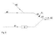
- Figs. 2 to 5 illustrate different ways of connecting the inventive vaporising apparatus in a system for delivering anaesthetic gas to a patient.
- the gas flowing into the container 2 through the gas delivery line 13 is comprised of a mixture of fresh gas entering from a line 15 and recycled gas entering from a line 14.
- the anaesthetic-containing gas is led on the outlet side through the line 17 to a line 19 leading to the patient, via a Y-coupling 18.
- the other branch of the Y-coupling 18 is comprised of the line 16 for exhalation gas.
- the coupling shown in Fig. 3 is modified inasmuch that the container 2 is connected between the Y-coupling 22 and the patient supply line 21.
- Reference numeral 24 identifies the inhalation hose
- 26 identifies the fresh gas hose
- reference 26 identifies the hose for re-circulated gas
- 23 identifies the exhalation hose.
- the container 2 is arranged in the fresh gas hose 31.
- the reference 32 identifies the patient supply hose
- 33 identifies the Y-coupling
- 34 identifies the hose for re-circulated gas
- 35 identifies the exhalation hose
- 36 identifies the inhalation hose.
- the container 2 is placed in the exhalation hose 41.
- Reference 42 identifies the patient supply hose, 44 identifies the inhalation hose, 45 identifies the fresh air hose, and 46 identifies the hose for re-circulated gas.
- the sensor 9 is placed separately from other components in the vaporising apparatus, although it is, of course, in signal communication therewith.
- the gas is enriched with anaesthetic in the exhalation hose 41, so that the re-circulation hose 46 will convey gaseous anaesthetic. That part of the exhalation hose 41 located downstream of the container 2, the re-circulation hose 46, and the inhalation hose 44 all form parts of the container outlet line.
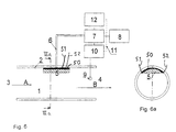
- Figs. 6-8, 6a-8a exemplify modified embodiments of the liquid-emitting device 5, although these apparatus are, in general, identical with the embodiment according to Figs. 1, 1a.
- the body 5 has a segmental form, in Figs. 7, 7a a form which is elongated transversely to the flow direction, and in Figs. 8, 8a a block-like form which is rounded to conform to the inner surface of the container 2.
- the heating device 50 may be placed within the liquid-emitting device 5 in both of these latter embodiments.
Abstract
Description
Claims (16)
- Gas supply apparatus for the supply of treatment gas, e.g. an anaesthetic, to a human being or to an animal, wherein the apparatus has a vaporiser which includes a vaporising chamber (1) that has a gas inlet means (3) and a gas outlet means (4) and in which a porous liquid-emitting device (5) is arranged to expose a liquid to said vaporising chamber (1) for vaporisation of liquid, and wherein the liquid-emitting device (5) is connected to a liquid supply device (6, 7) which communicates with an external liquid source (8), and wherein the gas outlet means (4) is adapted for connection to an inhalation means, characterised in that said liquid-emitting device (5) is adapted to expose the liquid exclusively via the porosities in the liquid-emitting device 5; and in that the apparatus includes liquid-heating means (50).
- Apparatus according to Claim 1, wherein the heating means (50) is adapted to heat the liquid present in the liquid-emitting device (5).
- Apparatus according to Claim 2, wherein the heating means (50) is arranged within the liquid-emitting device (5).
- Apparatus according to Claim 2, wherein the heating means (50) is arranged externally of but adjacent to said liquid-emitting device (5).
- Apparatus according to any one of Claims 1-4, wherein the heating means (50) is an electrical resistance.
- Apparatus according to any one of Claims 1-5, wherein the liquid supply means (7) is provided with liquid-quantity control means (10, 12).
- Apparatus according to any one of Claims 1-6, wherein said liquid supply means (7) includes a pump (7).
- Apparatus according to Claim 7, wherein the pump (7) is motor-driven.
- Apparatus according to Claim 7 or Claim 8, wherein the pump (7) is a controllable pump and therewith constitutes a component in said liquid-quantity control means (10, 12).
- Apparatus according to Claim 8, wherein the apparatus includes sensor means (9) for sensing the vaporised liquid content, said sensor means (9) being located downstream of said liquid-emitting device (5).
- Apparatus according to Claim 10, wherein said sensor means (9) includes an optical sensor.
- Apparatus according to Claim 10 or Claim 11, wherein said liquid-quantity control means (10, 12) is adapted to regulate the supply of liquid in response to said sensor means (9).
- Apparatus in accordance with any one of Claims 8-12, wherein said liquid-quantity control means (10, 12) is adapted to deliver per unit of time a quantity of liquid that is at most equal to the quantity of liquid that is vaporised in said liquid-emitting device (5) per unit of time.
- Apparatus according to any one of Claims 1-13, wherein said liquid-emitting device (5) is comprised of a plastic material.
- Apparatus according to any one of Claims 1-14, wherein said liquid-emitting device (5) lies against the inner surface of a wall (2) of said vaporisation chamber; and wherein the wall (2) includes on the surface thereof that lies against the liquid-emitting device (5) grooves (13) which communicate with said liquid supply means (6, 7).
- Apparatus according to any one of Claims 1-15, wherein the liquid-emitting device (5) has the form of a hollow cylinder.
Applications Claiming Priority (3)
| Application Number | Priority Date | Filing Date | Title |
|---|---|---|---|
| SE9701262 | 1997-04-07 | ||
| SE9701262A SE510741E (en) | 1997-04-07 | 1997-04-07 | Apparatus and method for supplying treatment gas to man or animals by gasification of treatment fluid |
| PCT/SE1998/000633 WO1998044977A1 (en) | 1997-04-07 | 1998-04-06 | Gas supply apparatus and method for the supply of treatment gas to a person or to an animal |
Publications (2)
| Publication Number | Publication Date |
|---|---|
| EP1007127A1 EP1007127A1 (en) | 2000-06-14 |
| EP1007127B1 true EP1007127B1 (en) | 2003-07-23 |
Family
ID=20406462
Family Applications (1)
| Application Number | Title | Priority Date | Filing Date |
|---|---|---|---|
| EP98915098A Expired - Lifetime EP1007127B1 (en) | 1997-04-07 | 1998-04-06 | Gas supply apparatus for the supply of treatment gas to a person or to an animal |
Country Status (9)
| Country | Link |
|---|---|
| US (1) | US6275650B1 (en) |
| EP (1) | EP1007127B1 (en) |
| JP (1) | JP4121563B2 (en) |
| AT (1) | ATE245458T1 (en) |
| AU (1) | AU728521B2 (en) |
| CA (1) | CA2285532C (en) |
| DE (1) | DE69816625T2 (en) |
| SE (1) | SE510741E (en) |
| WO (1) | WO1998044977A1 (en) |
Families Citing this family (45)
| Publication number | Priority date | Publication date | Assignee | Title |
|---|---|---|---|---|
| US6234167B1 (en) | 1998-10-14 | 2001-05-22 | Chrysalis Technologies, Incorporated | Aerosol generator and methods of making and using an aerosol generator |
| US6397838B1 (en) * | 1998-12-23 | 2002-06-04 | Battelle Pulmonary Therapeutics, Inc. | Pulmonary aerosol delivery device and method |
| US6501052B2 (en) | 2000-12-22 | 2002-12-31 | Chrysalis Technologies Incorporated | Aerosol generator having multiple heating zones and methods of use thereof |
| US6491233B2 (en) | 2000-12-22 | 2002-12-10 | Chrysalis Technologies Incorporated | Vapor driven aerosol generator and method of use thereof |
| US6701921B2 (en) | 2000-12-22 | 2004-03-09 | Chrysalis Technologies Incorporated | Aerosol generator having heater in multilayered composite and method of use thereof |
| US6681998B2 (en) | 2000-12-22 | 2004-01-27 | Chrysalis Technologies Incorporated | Aerosol generator having inductive heater and method of use thereof |
| US6799572B2 (en) | 2000-12-22 | 2004-10-05 | Chrysalis Technologies Incorporated | Disposable aerosol generator system and methods for administering the aerosol |
| US6640050B2 (en) | 2001-09-21 | 2003-10-28 | Chrysalis Technologies Incorporated | Fluid vaporizing device having controlled temperature profile heater/capillary tube |
| US6568390B2 (en) | 2001-09-21 | 2003-05-27 | Chrysalis Technologies Incorporated | Dual capillary fluid vaporizing device |
| US6804458B2 (en) | 2001-12-06 | 2004-10-12 | Chrysalis Technologies Incorporated | Aerosol generator having heater arranged to vaporize fluid in fluid passage between bonded layers of laminate |
| US6681769B2 (en) | 2001-12-06 | 2004-01-27 | Crysalis Technologies Incorporated | Aerosol generator having a multiple path heater arrangement and method of use thereof |
| US6701922B2 (en) | 2001-12-20 | 2004-03-09 | Chrysalis Technologies Incorporated | Mouthpiece entrainment airflow control for aerosol generators |
| US6772757B2 (en) * | 2002-10-25 | 2004-08-10 | Chrysalis Technologies Incorporated | Concentric controlled temperature profile fluid vaporizing device |
| SE0403017D0 (en) * | 2004-12-13 | 2004-12-13 | Hans Lambert | An anesthetic liquid vaporizer |
| AT507187B1 (en) | 2008-10-23 | 2010-03-15 | Helmut Dr Buchberger | INHALER |
| US8267081B2 (en) | 2009-02-20 | 2012-09-18 | Baxter International Inc. | Inhaled anesthetic agent therapy and delivery system |
| AT510837B1 (en) | 2011-07-27 | 2012-07-15 | Helmut Dr Buchberger | INHALATORKOMPONENTE |
| ES2543312T3 (en) | 2011-02-11 | 2015-08-18 | Batmark Limited | Component for inhaler |
| US8752544B2 (en) | 2011-03-21 | 2014-06-17 | General Electric Company | Medical vaporizer and method of monitoring of a medical vaporizer |
| US9072859B2 (en) | 2011-05-31 | 2015-07-07 | Naoyuki Ishikita | Anesthetic inhalation aid device and attachment used for the same |
| JP5808490B2 (en) | 2011-09-06 | 2015-11-10 | ブリティッシュ アメリカン タバコ (インヴェストメンツ) リミテッドBritish Americantobacco (Investments) Limited | Smoking material heating |
| KR102353233B1 (en) | 2011-09-06 | 2022-01-18 | 니코벤처스 트레이딩 리미티드 | Heating smokable material |
| AT511344B1 (en) | 2011-10-21 | 2012-11-15 | Helmut Dr Buchberger | INHALATORKOMPONENTE |
| US20130220314A1 (en) * | 2012-02-29 | 2013-08-29 | General Electric Company | Medical vaporizer with porous vaporization element |
| GB201207039D0 (en) | 2012-04-23 | 2012-06-06 | British American Tobacco Co | Heating smokeable material |
| GB2504076A (en) | 2012-07-16 | 2014-01-22 | Nicoventures Holdings Ltd | Electronic smoking device |
| GB2513639A (en) | 2013-05-02 | 2014-11-05 | Nicoventures Holdings Ltd | Electronic cigarette |
| GB2513637A (en) | 2013-05-02 | 2014-11-05 | Nicoventures Holdings Ltd | Electronic cigarette |
| GB2513638A (en) | 2013-05-02 | 2014-11-05 | Nicoventures Holdings Ltd | Electronic cigarette |
| GB201407426D0 (en) | 2014-04-28 | 2014-06-11 | Batmark Ltd | Aerosol forming component |
| GB2528673B (en) | 2014-07-25 | 2020-07-01 | Nicoventures Holdings Ltd | Aerosol provision system |
| GB2533135B (en) | 2014-12-11 | 2020-11-11 | Nicoventures Holdings Ltd | Aerosol provision systems |
| DE102014018602A1 (en) * | 2014-12-17 | 2016-06-23 | Drägerwerk AG & Co. KGaA | Narkosemittelverdunstereinheit |
| CN109259331A (en) * | 2015-04-22 | 2019-01-25 | 卓尔悦欧洲控股有限公司 | Atomizer and its aerosol generating device |
| US20170105455A1 (en) * | 2015-04-22 | 2017-04-20 | Joyetech Europe Holding Gmbh | Atomizer and aerosol generating device thereof |
| GB201511349D0 (en) | 2015-06-29 | 2015-08-12 | Nicoventures Holdings Ltd | Electronic aerosol provision systems |
| US11924930B2 (en) | 2015-08-31 | 2024-03-05 | Nicoventures Trading Limited | Article for use with apparatus for heating smokable material |
| US20170055584A1 (en) | 2015-08-31 | 2017-03-02 | British American Tobacco (Investments) Limited | Article for use with apparatus for heating smokable material |
| US20170312066A1 (en) * | 2015-11-30 | 2017-11-02 | The University Of Notre Dame Du Lac | Versatile inhalation anesthesia platform for small animal surgery |
| BR112018071824B1 (en) | 2016-04-27 | 2023-01-10 | Nicoventures Trading Limited | SUB-ASSEMBLY, SYSTEM, METHOD FOR MANUFACTURING A VAPORIZER AND ELECTRONIC STEAM DELIVERY DEVICE |
| US11491292B2 (en) | 2016-06-21 | 2022-11-08 | Sedana Medical Limited | Sedation device |
| AU2017281329A1 (en) | 2016-06-21 | 2019-01-31 | Sedana Medical Limited | A sedation device |
| US10610659B2 (en) | 2017-03-23 | 2020-04-07 | General Electric Company | Gas mixer incorporating sensors for measuring flow and concentration |
| US10946160B2 (en) | 2017-03-23 | 2021-03-16 | General Electric Company | Medical vaporizer with carrier gas characterization, measurement, and/or compensation |
| WO2019014373A1 (en) | 2017-07-11 | 2019-01-17 | Arizona Board Of Regents On Behalf Of Arizona State University | Detection and monitoring of dosage delivery for vaporized waxes, solids or viscous oils, and cannabinoids |
Family Cites Families (9)
| Publication number | Priority date | Publication date | Assignee | Title |
|---|---|---|---|---|
| DE2160561C3 (en) * | 1971-12-07 | 1985-05-15 | Hanns-Joachim Dr. 5000 Köln Hirtz | Device for treating the respiratory tract with warm air |
| US4110419A (en) * | 1975-04-18 | 1978-08-29 | Respiratory Care, Inc. | High-volume disposable and semi-disposable cartridge humidifier with self-contained cartridge sterilizing means, and related method |
| DE3116951C2 (en) * | 1981-04-29 | 1984-12-20 | Drägerwerk AG, 2400 Lübeck | Device for adding liquid anesthetics to the breathing gas to be supplied to the patient |
| US4943704A (en) * | 1989-02-06 | 1990-07-24 | Ryder International Corporation | Humidifier apparatus |
| US4914719A (en) * | 1989-03-10 | 1990-04-03 | Criticare Systems, Inc. | Multiple component gas analyzer |
| US5362328A (en) | 1990-07-06 | 1994-11-08 | Advanced Technology Materials, Inc. | Apparatus and method for delivering reagents in vapor form to a CVD reactor, incorporating a cleaning subsystem |
| DE4116512A1 (en) * | 1991-05-21 | 1992-11-26 | Draegerwerk Ag | NARCOSIS EVAPORATOR WITH FLOWABLE EVAPORATION ELEMENTS |
| US5259995A (en) * | 1991-10-30 | 1993-11-09 | Liquid Carbonic Industries Corporation | Vapor pressure device |
| US5509405A (en) * | 1994-11-21 | 1996-04-23 | Ohmeda Inc. | Pump flow vaporizer |
-
1997
- 1997-04-07 SE SE9701262A patent/SE510741E/en unknown
-
1998
- 1998-04-06 DE DE69816625T patent/DE69816625T2/en not_active Expired - Lifetime
- 1998-04-06 CA CA002285532A patent/CA2285532C/en not_active Expired - Lifetime
- 1998-04-06 AU AU69359/98A patent/AU728521B2/en not_active Expired
- 1998-04-06 JP JP54269798A patent/JP4121563B2/en not_active Expired - Lifetime
- 1998-04-06 EP EP98915098A patent/EP1007127B1/en not_active Expired - Lifetime
- 1998-04-06 WO PCT/SE1998/000633 patent/WO1998044977A1/en active IP Right Grant
- 1998-04-06 US US09/402,443 patent/US6275650B1/en not_active Expired - Fee Related
- 1998-04-06 AT AT98915098T patent/ATE245458T1/en not_active IP Right Cessation
Also Published As
| Publication number | Publication date |
|---|---|
| ATE245458T1 (en) | 2003-08-15 |
| SE510741E (en) | 2008-03-28 |
| CA2285532A1 (en) | 1998-10-15 |
| DE69816625T2 (en) | 2004-06-24 |
| US6275650B1 (en) | 2001-08-14 |
| DE69816625D1 (en) | 2003-08-28 |
| AU728521B2 (en) | 2001-01-11 |
| AU6935998A (en) | 1998-10-30 |
| SE9701262D0 (en) | 1997-04-07 |
| JP2001519699A (en) | 2001-10-23 |
| SE510741C2 (en) | 1999-06-21 |
| WO1998044977A1 (en) | 1998-10-15 |
| SE9701262L (en) | 1998-10-08 |
| CA2285532C (en) | 2008-10-07 |
| EP1007127A1 (en) | 2000-06-14 |
| JP4121563B2 (en) | 2008-07-23 |
Similar Documents
| Publication | Publication Date | Title |
|---|---|---|
| EP1007127B1 (en) | Gas supply apparatus for the supply of treatment gas to a person or to an animal | |
| AU725863B2 (en) | Vaporizer, use of such vaporizer and a method for vaporizing a liquid | |
| US4010748A (en) | Breathing air humidifier for respiration devices | |
| EP0496336B1 (en) | Apparatus for the administration of a respiratory gas and at least one anaesthetic | |
| US4201204A (en) | Breathing gas humidifier | |
| US5031612A (en) | System and method for delivering warm humidified air | |
| US4195044A (en) | Humidifier-nebulizer | |
| US5605146A (en) | Method and an arrangement in connection with vaporizing an anaesthetic | |
| US5771882A (en) | Anesthetic administration apparatus which delivers anesthetic in microdroplets | |
| US5769071A (en) | Humidifier systems | |
| US4060576A (en) | Method and apparatus for vapor saturated gas delivery | |
| CA2033770C (en) | Anaesthetic vaporisers | |
| US4086305A (en) | Humidifier for respirators having a sealed container water supply to a water storage tank | |
| FI104411B (en) | Arrangement in connection with anesthetic vaporization | |
| US4178334A (en) | High volume humidifier/nebulizer | |
| US6443150B1 (en) | Anaesthetic vaporizer | |
| EP0965372A2 (en) | Vaporiser | |
| US3282266A (en) | Method and apparatus for humidifying inhalation mixtures | |
| CN104023780A (en) | Vaporiser arrangement for breathing apparatus | |
| WO2006065202A1 (en) | An anaesthetic liquid vaporizer | |
| GB2279015A (en) | Vaporizer flow path | |
| KR20190132714A (en) | Heated Humidifier |
Legal Events
| Date | Code | Title | Description |
|---|---|---|---|
| PUAI | Public reference made under article 153(3) epc to a published international application that has entered the european phase |
Free format text: ORIGINAL CODE: 0009012 |
|
| 17P | Request for examination filed |
Effective date: 19991108 |
|
| AK | Designated contracting states |
Kind code of ref document: A1 Designated state(s): AT BE CH DE DK ES FI FR GB GR IE IT LI NL PT SE |
|
| RTI1 | Title (correction) |
Free format text: GAS SUPPLY APPARATUS FOR THE SUPPLY OF TREATMENT GAS TO A PERSON OR TO AN ANIMAL |
|
| GRAH | Despatch of communication of intention to grant a patent |
Free format text: ORIGINAL CODE: EPIDOS IGRA |
|
| RTI1 | Title (correction) |
Free format text: GAS SUPPLY APPARATUS FOR THE SUPPLY OF TREATMENT GAS TO A PERSON OR TO AN ANIMAL |
|
| RTI1 | Title (correction) |
Free format text: GAS SUPPLY APPARATUS FOR THE SUPPLY OF TREATMENT GAS TO A PERSON OR TO AN ANIMAL |
|
| GRAH | Despatch of communication of intention to grant a patent |
Free format text: ORIGINAL CODE: EPIDOS IGRA |
|
| GRAA | (expected) grant |
Free format text: ORIGINAL CODE: 0009210 |
|
| AK | Designated contracting states |
Designated state(s): AT BE CH DE DK ES FI FR GB GR IE IT LI NL PT SE |
|
| PG25 | Lapsed in a contracting state [announced via postgrant information from national office to epo] |
Ref country code: NL Free format text: LAPSE BECAUSE OF FAILURE TO SUBMIT A TRANSLATION OF THE DESCRIPTION OR TO PAY THE FEE WITHIN THE PRESCRIBED TIME-LIMIT Effective date: 20030723 Ref country code: LI Free format text: LAPSE BECAUSE OF FAILURE TO SUBMIT A TRANSLATION OF THE DESCRIPTION OR TO PAY THE FEE WITHIN THE PRESCRIBED TIME-LIMIT Effective date: 20030723 Ref country code: IT Free format text: LAPSE BECAUSE OF FAILURE TO SUBMIT A TRANSLATION OF THE DESCRIPTION OR TO PAY THE FEE WITHIN THE PRESCRIBED TIME-LIMIT;WARNING: LAPSES OF ITALIAN PATENTS WITH EFFECTIVE DATE BEFORE 2007 MAY HAVE OCCURRED AT ANY TIME BEFORE 2007. THE CORRECT EFFECTIVE DATE MAY BE DIFFERENT FROM THE ONE RECORDED. Effective date: 20030723 Ref country code: FI Free format text: LAPSE BECAUSE OF FAILURE TO SUBMIT A TRANSLATION OF THE DESCRIPTION OR TO PAY THE FEE WITHIN THE PRESCRIBED TIME-LIMIT Effective date: 20030723 Ref country code: CH Free format text: LAPSE BECAUSE OF FAILURE TO SUBMIT A TRANSLATION OF THE DESCRIPTION OR TO PAY THE FEE WITHIN THE PRESCRIBED TIME-LIMIT Effective date: 20030723 Ref country code: BE Free format text: LAPSE BECAUSE OF FAILURE TO SUBMIT A TRANSLATION OF THE DESCRIPTION OR TO PAY THE FEE WITHIN THE PRESCRIBED TIME-LIMIT Effective date: 20030723 Ref country code: AT Free format text: LAPSE BECAUSE OF FAILURE TO SUBMIT A TRANSLATION OF THE DESCRIPTION OR TO PAY THE FEE WITHIN THE PRESCRIBED TIME-LIMIT Effective date: 20030723 |
|
| REG | Reference to a national code |
Ref country code: GB Ref legal event code: FG4D |
|
| REG | Reference to a national code |
Ref country code: CH Ref legal event code: EP |
|
| REG | Reference to a national code |
Ref country code: IE Ref legal event code: FG4D |
|
| REF | Corresponds to: |
Ref document number: 69816625 Country of ref document: DE Date of ref document: 20030828 Kind code of ref document: P |
|
| PG25 | Lapsed in a contracting state [announced via postgrant information from national office to epo] |
Ref country code: SE Free format text: LAPSE BECAUSE OF FAILURE TO SUBMIT A TRANSLATION OF THE DESCRIPTION OR TO PAY THE FEE WITHIN THE PRESCRIBED TIME-LIMIT Effective date: 20031023 Ref country code: GR Free format text: LAPSE BECAUSE OF FAILURE TO SUBMIT A TRANSLATION OF THE DESCRIPTION OR TO PAY THE FEE WITHIN THE PRESCRIBED TIME-LIMIT Effective date: 20031023 Ref country code: DK Free format text: LAPSE BECAUSE OF FAILURE TO SUBMIT A TRANSLATION OF THE DESCRIPTION OR TO PAY THE FEE WITHIN THE PRESCRIBED TIME-LIMIT Effective date: 20031023 |
|
| PG25 | Lapsed in a contracting state [announced via postgrant information from national office to epo] |
Ref country code: ES Free format text: LAPSE BECAUSE OF FAILURE TO SUBMIT A TRANSLATION OF THE DESCRIPTION OR TO PAY THE FEE WITHIN THE PRESCRIBED TIME-LIMIT Effective date: 20031103 |
|
| RAP2 | Party data changed (patent owner data changed or rights of a patent transferred) |
Owner name: HUDSON RCI AB |
|
| NLV1 | Nl: lapsed or annulled due to failure to fulfill the requirements of art. 29p and 29m of the patents act | ||
| PG25 | Lapsed in a contracting state [announced via postgrant information from national office to epo] |
Ref country code: PT Free format text: LAPSE BECAUSE OF FAILURE TO SUBMIT A TRANSLATION OF THE DESCRIPTION OR TO PAY THE FEE WITHIN THE PRESCRIBED TIME-LIMIT Effective date: 20031223 |
|
| REG | Reference to a national code |
Ref country code: CH Ref legal event code: PL |
|
| ET | Fr: translation filed | ||
| PLBE | No opposition filed within time limit |
Free format text: ORIGINAL CODE: 0009261 |
|
| STAA | Information on the status of an ep patent application or granted ep patent |
Free format text: STATUS: NO OPPOSITION FILED WITHIN TIME LIMIT |
|
| 26N | No opposition filed |
Effective date: 20040426 |
|
| PGFP | Annual fee paid to national office [announced via postgrant information from national office to epo] |
Ref country code: IE Payment date: 20140416 Year of fee payment: 17 |
|
| REG | Reference to a national code |
Ref country code: IE Ref legal event code: MM4A |
|
| REG | Reference to a national code |
Ref country code: FR Ref legal event code: PLFP Year of fee payment: 19 |
|
| PG25 | Lapsed in a contracting state [announced via postgrant information from national office to epo] |
Ref country code: IE Free format text: LAPSE BECAUSE OF NON-PAYMENT OF DUE FEES Effective date: 20150406 |
|
| REG | Reference to a national code |
Ref country code: FR Ref legal event code: PLFP Year of fee payment: 20 |
|
| PGFP | Annual fee paid to national office [announced via postgrant information from national office to epo] |
Ref country code: FR Payment date: 20170412 Year of fee payment: 20 Ref country code: DE Payment date: 20170412 Year of fee payment: 20 Ref country code: GB Payment date: 20170420 Year of fee payment: 20 |
|
| REG | Reference to a national code |
Ref country code: DE Ref legal event code: R071 Ref document number: 69816625 Country of ref document: DE |
|
| REG | Reference to a national code |
Ref country code: GB Ref legal event code: PE20 Expiry date: 20180405 |
|
| PG25 | Lapsed in a contracting state [announced via postgrant information from national office to epo] |
Ref country code: GB Free format text: LAPSE BECAUSE OF EXPIRATION OF PROTECTION Effective date: 20180405 |