EP1006334B1 - Cible thermique - Google Patents
Cible thermique Download PDFInfo
- Publication number
- EP1006334B1 EP1006334B1 EP99403012A EP99403012A EP1006334B1 EP 1006334 B1 EP1006334 B1 EP 1006334B1 EP 99403012 A EP99403012 A EP 99403012A EP 99403012 A EP99403012 A EP 99403012A EP 1006334 B1 EP1006334 B1 EP 1006334B1
- Authority
- EP
- European Patent Office
- Prior art keywords
- modules
- module
- target
- target according
- longitudinal
- Prior art date
- Legal status (The legal status is an assumption and is not a legal conclusion. Google has not performed a legal analysis and makes no representation as to the accuracy of the status listed.)
- Expired - Lifetime
Links
Images

Classifications
-
- F—MECHANICAL ENGINEERING; LIGHTING; HEATING; WEAPONS; BLASTING
- F41—WEAPONS
- F41J—TARGETS; TARGET RANGES; BULLET CATCHERS
- F41J2/00—Reflecting targets, e.g. radar-reflector targets; Active targets transmitting electromagnetic or acoustic waves
- F41J2/02—Active targets transmitting infrared radiation
Definitions
- the present invention relates in particular to the target domain and more particularly for object a thermal target for the realization of an image thermal composed of several bands and comprising at least one layer in electrically conductive material connected to two electrodes connected to means capable of generating, between them, a potential difference, said layer being fixed on a support.
- Targets also called targets, allow in particular to quantify the performances of these optronic devices, relating to the contrasts in the visible or infrared thermal domains, and detection ranges, recognition and identification of remote systems real.
- STANAG 43 47 AND STANAG 4349 documents define procedures relating to the testing of optronic devices.
- the first concerns the definition of nominal static range performance of thermal imaging systems and the second, the measurement of the minimum resolvable temperature difference of thermal imaging systems.
- the function of the optronic system is to provide information visual to the observer. This must necessarily be qualified and quantified.
- Detection corresponds to the action of detecting a hot spot in a scene.
- Recognition is one that allows you to know the type of object that is found in the scene (tank, light vehicle, infantryman, etc.).
- Identification is the action which consists in determining very precisely the object (AMX30, T72, etc.).
- the system has to solve a certain number points of the object contained in its smallest dimension, this number being a function the type of test considered (Detection, Recognition or Identification).
- test patterns used for the visible channel correspond to the same frequency spatial than those of the thermal infrared channel.
- Each type of test (Detection, Recognition or Identification) and each mode, (visible or thermal infrared) requires a specific target calculated according to the criteria relating to the separating power, according to a 50% probability of success.
- the test patterns used are as follows: Night detection - uniform objective - width of a bar: 2.30 m Night recognition 3.5 pairs of lines per objective width of a bar: 0.32 m Night identification 7 pairs of lines per objective width of a bar: 0.16 m
- the test patterns used are as follows: Day detection Uniform lens Bar width: 2.30 m Day recognition 3.5 pairs of lines per objective width of a bar: 0.32 m Day identification 7 pairs of lines per objective width of a bar: 0.16 m.
- pitch of the detector array can be different depending on the two directions, horizontal and vertical, double the number of sights in order to obtain the two positions.
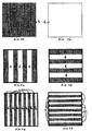
- the bands 5 consist of a shade of color, and the bands 6 by another shade of this same color, for example two shades of gray with a contrast for example of 20%, the contrast between white and black being considered to be equal to 100%.
- the bands correspond to emitting surfaces of a infrared radiation, the bands 5 corresponding to a surface at a first temperature T1, and the bands 6 to a surface at a second temperature T2.
- the object of the invention is to remedy these drawbacks by proposing a very simple manufacturing target, also very simple maintenance and limiting the loss of time when changing the type of test.
- the proposed solution is a thermal thermal target for the realization in particular a thermal image composed of several bands and comprising at at least one layer of electrically conductive material connected to two electrodes connected to means capable of generating a potential difference between them, target characterized in that it comprises at least one module resting on a support and forming all or part of a strip and comprising a support structure on all or part of which rests at least one layer of material electrically conductive connected to two electrodes connected to suitable means to generate, between them, a potential difference and in that it involves means able to allow the rotation of all or part of the module, these means can be constituted by axle-bearing assemblies, the bearings being able to be secured to the support and the axes secured to the module.
- It may also include means capable of rotating all or part of the module, these means being able to be constituted by a motor, for example, of the type step by step and two directions of rotation, or asynchronous under voltage safety with limit stop.
- it comprises at least two modules independent each forming all or part of a band and each comprising at at least two longitudinal faces and a support structure on all or part of which rests at least one layer of electrically conductive material connected with two electrodes connected to means capable of generating, between them, a potential difference, and in that it includes means capable of enabling the rotation of all or part of each of the modules.
- the at least two faces of each of the modules are painted, the color of the paint or the shade of the first longitudinal face being different from that of the second longitudinal face
- it comprises at least part of the support which is common to all modules and modules can be arranged in the same plane and all of said first longitudinal faces of each of modules can be positioned in the same plane using means suitable for allow the rotation of all or part of the module.
- it may include means capable of allowing its rotation on itself, and more particularly, in the plan it defines, as well as means capable of driving the target in rotation in the plane it defines.
- At least one of the modules comprises a first and a second face covered by a layer of material electrically conductive connected to two electrodes connected to suitable means generating between them a potential difference, said layer being fixed on the support structure
- At least one of the modules includes a second longitudinal face of material not connected to electrodes, this material which may or may not be electrically conductive.
- the said layer or layers electrically conductive consists of a glass-carbon fiber fabric.
- the electrodes are made up of metallic braids.
- the conductive layer is held on the braid using one or more clips the total length of the jaws of which is preferably greater than or equal to the length of braid.
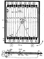
- FIG. 2 shows a target 10 according to a first embodiment particular of the invention.
- This target 10 comprises a support comprising a frame 11 and support elements 12, 13, 15, 16 and on which are fixed independent and juxtaposed modules 14 1 to 14 14 .
- the end of each of the support elements 12 is constituted by a bearing 13 intended to receive an axis 23 of a first module. It further comprises a thread in which is fixed one of the ends of a cylindrical spacer 15 threaded at its two ends, another bearing 16, intended for a second module juxtaposed with the first module, being fixed at the other end of this spacer 15.
- each module 14 i comprises two U-shaped profiles 20 and 21 made of insulating material, on each of which is fixed an axis, respectively 22 and 23, the axis 22 being connected to a motor M of the stepping type. not powered by means 60 capable of generating a potential difference of 48V.
- These U-shaped sections 20 and 21 have a height of 0.16 m, a width of approximately 0.05m and a depth of 0.05m, the distance between the two branches 26 of the U as well as their length being approximately 0.03m.
- Each module 14 i further comprises a wooden board 28 or a thermally insulating material (wood-polyurethane-wood sandwich or other) with a height of 0.16m, a width of about 2.36m and a 0.03m depth which can be fixed to the profiles by force fitting or by any other fixing means.
- a wooden board 28 or a thermally insulating material wood-polyurethane-wood sandwich or other
- each of the longitudinal faces 29, 30 of the board 28 is fixed a layer, respectively 31 and 33, of electrically conductive material connected to two electrodes, respectively 70a; 70b and 71a; 71b, having ends in form of plate and themselves connected to the means 60 capable of generating between they a potential difference.
- These layers 31 and 33 of electrically conductive material can by example consist of a fiberglass / carbon fabric such as for example that HEXEL 43596 16/34 from HEXEL or CG202 from company SEAL.
- the width of the layers electrically conductive 31 and 33 is chosen slightly higher than that of the board 28, for example 2.38 m, so that their ends are folded over the lateral surfaces 32 of the board 28 without touching each other and that the board and layers 31 and 33 and the plate-like ends of the electrodes are force-fitted into the U-profiles 20 and 21.
- the frame 11 is fixed to a support element 17 shown in dotted lines and secured on the one hand to an axis 18 connected to a motor 19 and whose axis of symmetry is confused with that of the support 12, and on the other hand to two other elements of support 40 each ending with a foot 41 which can serve as support for a forklift.
- At least one thermocouple is placed on each of the electrically conductive layers 31 of each of the modules.
- Each of these thermocouples is connected to a regulation control unit, for example of the brand JUMO, itself connected to the voltage generator 60, preferably portable, this generator being connected to said electrodes 70a; 70b; 71a; 71b.
- the temperature is regulated at a setpoint T1 over the entire said first conductive layer 31 and at a setpoint T2 over the entire said second conductive layer 33.
- the electrically conductive layers 31 and 33 are covered with a layer of different color paint, in this case two shades of green, these two colors therefore presenting a contrast between them.
- the operation of the target according to this embodiment is as follows, knowing that in thermal infrared mode, a potential difference is generated between the electrodes 70a and 70b in order to obtain a temperature T1 on the face longitudinal 29 as well as between the electrodes 71a and 71b in order to obtain a temperature T2 on the longitudinal face 30, while in visible mode, no potential difference is not generated between the different electrodes.
- all the longitudinal faces 30 of the modules are positioned, using the motors M1 to M14 of the respective modules 14 1 to 14 14 , on the front face of the target , this face being defined as that visible by the optronic device to be tested.
- all the longitudinal faces 29 of the modules 14 1 to 14 14 that is to say those covered by a layer 31 of electrically material conductor, are positioned, using the motors M1 to M14 of the respective modules 14 1 to 14 14, on the front face of the target
- the modules are associated in successive pairs, two modules of the same pair presenting the same face 29 or 30 to the objective, while the two modules of the next pair present as a pair, the same face 29 or 30, these faces being different from those presented by the previous pair of modules.
- the modules 14 1 , 14 2 , 14 5 , 14 6 , 14 9 , 14 10 , 14 13 , 14 14 for example have their longitudinal face 29 covered with a layer 31 of electrically conductive material while the modules 14 3 , 14 4 , 14 7 , 14 8 , 14 11 , 14 12 , have their wooden face 30.
- the modules with even index 14 2 , 14 4 , 14 6 ... each have the same longitudinal face while the modules with odd index 14 1 , 14 3 , 14 5 ... they too have the same face to each other, this face being different from that presented by the modules with an even index.
- FIG. 4 shows a target 10 according to a second embodiment particular of the invention.
- This target 10a comprises a support comprising a frame 11a and means able to allow, for each module, its rotation but not its translation.
- These means include in particular bearings 13a fixed to the frame 11a.
- each module 14 i comprises two U-shaped profiles 20a and 21a made of conductive material, on each of which is fixed a tube, respectively 22a and 23a, the axis 23a being connected to a motor M of the asynchronous type and powered by means 60a capable of generating a potential difference of 48V.
- These sections at 20a and 21a have a height of 0.16m, a width of approximately 0.05m and a depth of 0.05m, the distance between the two branches 26 of the U as well as their length being approximately 0.03m.
- Each module 14 i further comprises two plywood boards 28a and 28b with a height of 0.16m, a width of about 2.36m and a depth of 0.03m. These two boards are separated by a layer 31 a of electrically conductive material connected to two electrodes, in this case the U-shaped profiles 20a and 21a, themselves connected to the means 60a.
- the sandwich structure constituted by the two boards separated by the layer 31a of electrically conductive material can be fixed on the profiles by force fitting or by fixing means such as bolts, screws, etc.
- This layer 31 which may for example be constituted by a fiber fabric glass / carbon having a height of 0.16m and a width greater than 2.36, by example 2.4m so that its ends can be folded against the surfaces side of one and / or the other of the boards 28a, 28b, and is thus in contact with the U-shaped sections which constitute the electrodes.
- the frame 11 is fixed to a support element 17 shown in dotted lines and secured on the one hand of an axis 18 connected to a motor 19 and whose axis of symmetry is coincident with that of the support 12, and on the other hand to two other support elements 40 each ending with a foot 41 which can serve as a support for a carriage elevator.
- the longitudinal face 29a of the board 28a is covered with a first shade of gray while the longitudinal face 30a of the plate 28b is covered with another shade of gray, the contrast between these two shades being 20%.
- thermocouples were positioned, one on the module 14 1 and the other on the module 14 9 . All the modules which have to be regulated at the temperature T1 are regulated like the module 14 1 while all the modules which have to be regulated at the temperature T2 are regulated like the module 14 9.
- thermocouples are each connected to a regulation control unit, for example of the brand JUMO, itself connected to the voltage generator 60, preferably portable, this generator being connected to said electrodes 20 and 21 formed in this embodiment by the U-shaped profiles.
- a regulation control unit for example of the brand JUMO
- this generator being connected to said electrodes 20 and 21 formed in this embodiment by the U-shaped profiles.
- the temperature is regulated at a setpoint value T1 for the module 14 1 as well as for all the modules having to be at the temperature T1 and at a setpoint value T2 for the module 14 8 as well as for all modules must be at temperature T2.
- all the faces comprising the darkest paint in this case the faces 29a, that is to say those having a better emission coefficient, are preferably positioned, using the motors M1 to M14 of the respective modules 14 1 to 14 14 , on the front face of the target, this face being defined as that visible by the optronic device to be tested, and the temperature of all the faces 29a is voltage-regulated at temperature T1.
- the same positioning of the modules as that described in the vertical detection frame can be used, just stop regulating the temperature at temperature T1 but at temperature T2.
- the same positioning of the modules as that described in the context of vertical detection can be used but the modules are associated by successive pairs of modules, two modules of the same pair being regulated at one of the temperatures T1 or T2, the two modules of the next pair being regulated to the other of temperatures T1 or T2.
- the longitudinal faces 29a of the modules 14 1 , 14 2 , 14 5 , 14 6 , 14 9 , 14 10 , 14 13 , 14 14 are regulated at temperature T1 while the longitudinal faces 29a of the modules 14 3 , 14 4 , 14 7 , 14 8 , 14 11 , 14 12 , are regulated at temperature T2.
- the same positioning of the modules as that described in the context of vertical detection can be used but the longitudinal faces 29a of the modules with even index 14 2 , 14 4 , 14 6 ... are regulated at temperature T2 while the longitudinal faces 29a of the modules with an odd index 14 1 , 14 3 , 14 5 ... are regulated at temperature T1.
- the bands can have a shape any or have that of a rectangle, a square, a circle ...
- the electrodes can consist of metallic braids held by clamps fixed to a support.
- Modules may have a fixed electrically conductive layer and have a cover with an area equal to half that of the area longitudinal of the module, this cover being able to pivot to hide half of the module.
- the modules can also have more than two longitudinal sides, for example example three or four then forming a parallelepiped which can in particular present to the optronic device and in visible mode four shades of the same color, or four different colors. It should be noted that in the latter case, the modules, if they must be juxtaposed, are preferably positioned in two different planes to allow their rotation.
- the position of the modules is controlled from a module control comprising a three-position switch (detection, recognition, identification) and a two-position switch (horizontal or vertical).
- the modules can be placed inside an envelope waterproof or can be covered, at least in part, by a waterproof film.
Landscapes
- Engineering & Computer Science (AREA)
- Physics & Mathematics (AREA)
- Electromagnetism (AREA)
- Radar, Positioning & Navigation (AREA)
- Remote Sensing (AREA)
- General Engineering & Computer Science (AREA)
- Physical Vapour Deposition (AREA)
- Photometry And Measurement Of Optical Pulse Characteristics (AREA)
- Eye Examination Apparatus (AREA)
- Thermotherapy And Cooling Therapy Devices (AREA)
- Electronic Switches (AREA)
Description
- normalement à l'axe du système d'observation
- au centre du champ
- à une distance D telle que les barres successives, correspondant à une certaine fréquence, puissent être discernées par le dispositif optronique testé.
- de l'objectif
- du détecteur
- de l'électronique
- du système de visualisation
- de l'observateur (acuité visuelle normale, une bonne faculté d'appréciation des couleurs et une bonne expérience de ce type de mesures)
- de la transmission atmosphérique.
| Détection de nuit | - objectif uniforme |
| - largeur d'une barre : 2,30 m | |
| Reconnaissance de nuit | 3,5 paires de lignes par objectif |
| largeur d'une barre : 0,32 m | |
| Identification de nuit | 7 paires de lignes par objectif |
| largeur d'une barre : 0,16 m |
| Détection de jour | Objectif uniforme |
| Largeur d'une barre : 2,30 m | |
| Reconnaissance de jour | 3,5 paires de lignes par objectif |
| largeur d'une barre : 0,32 m | |
| Identification de jour | 7 paires de lignes par objectif |
| largeur d'une barre : 0,16 m. |
- la détection verticale,
- la détection horizontale,
- la reconnaissance verticale,
- la reconnaissance horizontale,
- l'identification verticale,
- l'identification horizontale.
- les figures 1a à 1f montrent des schémas de cibles selon l'état de la technique et utilisées pour des essais de détection, reconnaissance et identification,
- la figure 2 présente un mode de réalisation d'une cible selon l'invention,
- la figure 3 présente une coupe transversale d'un module selon l'invention.
- la figure 4 présente un deuxième mode de réalisation d'une cible selon l'invention,
- la figure 5 présente une coupe transversale d'un module selon ce deuxième mode de réalisation.
Claims (9)
- Cible thermique pour la réalisation, sur sa face avant, notamment d'une image thermique composée de plusieurs bandes (5,6) et comportant au moins un module (141 ;... ; 1414) formant tout ou partie d'une bande (5 ; 6) et comportant chacun au moins deux faces longitudinales (29 ; 29a ; 30a ; 30) et une structure support (20 ; 21 ; 28 ; 28a, 28b) sur tout ou partie de laquelle repose au moins une couche (31, 31a) en matériau électriquement conducteur reliée à deux électrodes (20a ; 21a ; 70a ; 70b) connectées à des moyens (60 ; 60a) aptes à générer, entre elles, une différence de potentiel, cible caractérisée en ce que les au moins deux faces longitudinales (29 ; 29a ; 30a ; 30) de chacun des modules sont peintes, la couleur de la peinture ou la nuance de la première face longitudinale (29 ; 29a) étant différente de celle de la deuxième face longitudinale (30; 30a) et en ce qu'elle comporte des moyens ( 13, 16, 22 , 23) aptes à permettre la rotation de tout ou partie de chacun des modules de façon à positionner l'une ou l'autre des dites au moins deux faces longitudinales (29 ; 29a ; 30a ; 30) sur la face avant de la cible.
- Cible thermique selon la revendication 1, caractérisée en ce que les moyens ( 13, 16, 22 , 23) aptes à permettre la rotation de tout ou partie de chacun desdits modules sont constitués par des paliers (13 ; 16) solidaires du support (11, 12, 13 , 15 ; 16) et des axes (22 ; 23) solidaires du module.
- Cible thermique selon l'une quelconque des revendications 1 et 2, caractérisée en ce qu'elle comporte des moyens (M) aptes à entraíner en rotation tout ou partie du module.
- Cible thermique selon la revendications 3, caractérisée en ce que les moyens (M) aptes à entraíner en rotation tout ou partie du module (141 ;... ; 1414) comportent un moteur.
- Cible thermique selon l'une quelconque des revendications 1 à 4, caractérisée en ce qu'elle comporte au moins une partie (11) du support (11 ; 12 ; 13 : 15 ; 16 ) qui est commune à tous les modules (141 ;... ; 1414).
- Cible thermique selon l'une quelconque des revendications 1 à 5, caractérisée en ce que les modules sont disposés dans un même plan et toutes lesdites premières faces longitudinales (29 ; 29a) de chacun des modules peuvent être positionnées dans un même plan à l'aide des moyens ( 13, 16, 22, 23) aptes à permettre la rotation de tout ou partie du module.
- Cible thermique selon l'une quelconque des revendications 1 à 6, caractérisée en ce qu'elle comporte des moyens (17; 18; 19; 40; 41) aptes à permettre sa rotation sur elle-même.
- Cible thermique selon la revendication 7, caractérisée en ce qu'elle comporte des moyens (18 ; 19) aptes à entraíner la cible en rotation dans le plan qu'elle définit.
- Cible thermique selon l'une quelconque des revendications 1 à 8, caractérisée en ce qu'elle comporte au moins un module (141 ;... ; 1414) comportant une deuxième couche (33) en matériau électriquement conducteur reliée à deux électrodes (71a ; 71b) connectées à des moyens aptes (60) à générer, entre elles, une différence de potentiel, et reposant sur la structure support (28 ; 28a ;28b), lesdites première et deuxième couche (31 ; 33) en matériau électriquement conducteur n'étant pas jointive.
Applications Claiming Priority (2)
| Application Number | Priority Date | Filing Date | Title |
|---|---|---|---|
| FR9815263 | 1998-12-03 | ||
| FR9815263A FR2786861A1 (fr) | 1998-12-03 | 1998-12-03 | Cible thermique |
Publications (2)
| Publication Number | Publication Date |
|---|---|
| EP1006334A1 EP1006334A1 (fr) | 2000-06-07 |
| EP1006334B1 true EP1006334B1 (fr) | 2001-04-25 |
Family
ID=9533532
Family Applications (1)
| Application Number | Title | Priority Date | Filing Date |
|---|---|---|---|
| EP99403012A Expired - Lifetime EP1006334B1 (fr) | 1998-12-03 | 1999-12-03 | Cible thermique |
Country Status (5)
| Country | Link |
|---|---|
| EP (1) | EP1006334B1 (fr) |
| AT (1) | ATE200825T1 (fr) |
| DE (1) | DE69900092T2 (fr) |
| ES (1) | ES2157687T3 (fr) |
| FR (1) | FR2786861A1 (fr) |
Family Cites Families (3)
| Publication number | Priority date | Publication date | Assignee | Title |
|---|---|---|---|---|
| US4546983A (en) * | 1981-09-18 | 1985-10-15 | Tvi Energy Corporation | Multi-spectral target |
| US4524386A (en) * | 1982-04-12 | 1985-06-18 | The United States Of America As Represented By The Secretary Of The Army | Thermal target display system |
| US4946171A (en) * | 1989-01-03 | 1990-08-07 | Eastman Kodak Company | Live fire target modular support structure |
-
1998
- 1998-12-03 FR FR9815263A patent/FR2786861A1/fr active Pending
-
1999
- 1999-12-03 DE DE69900092T patent/DE69900092T2/de not_active Expired - Lifetime
- 1999-12-03 EP EP99403012A patent/EP1006334B1/fr not_active Expired - Lifetime
- 1999-12-03 AT AT99403012T patent/ATE200825T1/de not_active IP Right Cessation
- 1999-12-03 ES ES99403012T patent/ES2157687T3/es not_active Expired - Lifetime
Also Published As
| Publication number | Publication date |
|---|---|
| FR2786861A1 (fr) | 2000-06-09 |
| DE69900092D1 (de) | 2001-05-31 |
| DE69900092T2 (de) | 2001-10-25 |
| ATE200825T1 (de) | 2001-05-15 |
| ES2157687T3 (es) | 2001-08-16 |
| EP1006334A1 (fr) | 2000-06-07 |
Similar Documents
| Publication | Publication Date | Title |
|---|---|---|
| FR2557996A1 (fr) | Procede de formation d'image et appareil pour sa mise en oeuvre. | |
| US12615010B2 (en) | System and method of amplifying solar panel output | |
| EP2652570A1 (fr) | Systeme de commande de vitrages actifs comprenant un capteur d' eblouissement | |
| EP1982226A1 (fr) | Systeme optique pour visualiser une image a la surface d' un panneau solaire | |
| FR2708380A1 (fr) | Dispositif d'affichage d'images et circuit de commande associé. | |
| EP0704877A1 (fr) | Protection électrique d'une anode d'écran plat de visualisation | |
| EP0563356A1 (fr) | Dispositif et methode de controle non destructif et continu d'une variation de l'epaisseur de profiles. | |
| WO2006131656A2 (fr) | Appareillage de mesure de temperature sans contact d’echantillons de materiaux places sous vide | |
| EP1006334A1 (fr) | Cible thermique | |
| EP0213017B1 (fr) | Dispositif pour la restitution et/ou l'analyse d'images en couleurs utilisant un tube cathodique ligne à écran sur fibres optiques | |
| US6315294B1 (en) | Heat target | |
| US4820929A (en) | Dynamic infrared simulation cell | |
| CA2658035C (fr) | Detecteur thermique a haute isolation | |
| CA1317628C (fr) | Dispositif pour engendrer une image infrarouge | |
| FR2525355A1 (fr) | Dispositif electro-optique | |
| EP2976607B1 (fr) | Système de détection et d'imagerie par analyse spectrale dans plusieurs bandes de longueurs d'onde | |
| US5508145A (en) | Infrared imaging materials | |
| EP0007885A1 (fr) | Dispositif d'affichage sélectif d'une pluralité d'informations et son procédé de fabrication | |
| EP3379661B1 (fr) | Dispositif d'amplification laser à contrôle actif de la qualité de faisceau et barres d'extrémité | |
| FR2608842A1 (fr) | Transducteur photo-electronique utilisant une cathode emissive a micropointes | |
| FR2789485A1 (fr) | Cible thermique | |
| FR2802654A1 (fr) | Mire et procede et dispositif de protection d'un objet contre un engin a detection infrarouge | |
| EP3433910B1 (fr) | Dispositif d'amplification laser à contrôle actif de la qualité de faisceau | |
| EP1530238A1 (fr) | Dispositif de détection de rayonnements infrarouges à détecteurs bolométriques | |
| FR2731862A1 (fr) | Dispositif de mise au point d'appareillage de thermographie |
Legal Events
| Date | Code | Title | Description |
|---|---|---|---|
| PUAI | Public reference made under article 153(3) epc to a published international application that has entered the european phase |
Free format text: ORIGINAL CODE: 0009012 |
|
| 17P | Request for examination filed |
Effective date: 19991210 |
|
| AK | Designated contracting states |
Kind code of ref document: A1 Designated state(s): AT BE CH CY DE DK ES FI FR GB GR IE IT LI LU MC NL PT SE |
|
| AX | Request for extension of the european patent |
Free format text: AL;LT;LV;MK;RO;SI |
|
| 17Q | First examination report despatched |
Effective date: 20000524 |
|
| GRAG | Despatch of communication of intention to grant |
Free format text: ORIGINAL CODE: EPIDOS AGRA |
|
| GRAG | Despatch of communication of intention to grant |
Free format text: ORIGINAL CODE: EPIDOS AGRA |
|
| GRAH | Despatch of communication of intention to grant a patent |
Free format text: ORIGINAL CODE: EPIDOS IGRA |
|
| GRAH | Despatch of communication of intention to grant a patent |
Free format text: ORIGINAL CODE: EPIDOS IGRA |
|
| AKX | Designation fees paid |
Free format text: AT BE CH CY DE DK ES FI FR GB GR IE IT LI LU MC NL PT SE |
|
| GRAA | (expected) grant |
Free format text: ORIGINAL CODE: 0009210 |
|
| AK | Designated contracting states |
Kind code of ref document: B1 Designated state(s): AT BE CH CY DE DK ES FI FR GB GR IE IT LI LU MC NL PT SE |
|
| PG25 | Lapsed in a contracting state [announced via postgrant information from national office to epo] |
Ref country code: IE Free format text: LAPSE BECAUSE OF FAILURE TO SUBMIT A TRANSLATION OF THE DESCRIPTION OR TO PAY THE FEE WITHIN THE PRESCRIBED TIME-LIMIT Effective date: 20010425 Ref country code: FI Free format text: LAPSE BECAUSE OF FAILURE TO SUBMIT A TRANSLATION OF THE DESCRIPTION OR TO PAY THE FEE WITHIN THE PRESCRIBED TIME-LIMIT Effective date: 20010425 Ref country code: CY Free format text: LAPSE BECAUSE OF NON-PAYMENT OF DUE FEES Effective date: 20010425 Ref country code: AT Free format text: LAPSE BECAUSE OF FAILURE TO SUBMIT A TRANSLATION OF THE DESCRIPTION OR TO PAY THE FEE WITHIN THE PRESCRIBED TIME-LIMIT Effective date: 20010425 |
|
| REF | Corresponds to: |
Ref document number: 200825 Country of ref document: AT Date of ref document: 20010515 Kind code of ref document: T |
|
| REG | Reference to a national code |
Ref country code: CH Ref legal event code: EP |
|
| REF | Corresponds to: |
Ref document number: 69900092 Country of ref document: DE Date of ref document: 20010531 |
|
| ITF | It: translation for a ep patent filed | ||
| REG | Reference to a national code |
Ref country code: IE Ref legal event code: FG4D Free format text: FRENCH |
|
| REG | Reference to a national code |
Ref country code: CH Ref legal event code: NV Representative=s name: BUGNION S.A. * BUGNION S.A. |
|
| PG25 | Lapsed in a contracting state [announced via postgrant information from national office to epo] |
Ref country code: DK Free format text: LAPSE BECAUSE OF FAILURE TO SUBMIT A TRANSLATION OF THE DESCRIPTION OR TO PAY THE FEE WITHIN THE PRESCRIBED TIME-LIMIT Effective date: 20010725 |
|
| PG25 | Lapsed in a contracting state [announced via postgrant information from national office to epo] |
Ref country code: PT Free format text: LAPSE BECAUSE OF FAILURE TO SUBMIT A TRANSLATION OF THE DESCRIPTION OR TO PAY THE FEE WITHIN THE PRESCRIBED TIME-LIMIT Effective date: 20010726 |
|
| PG25 | Lapsed in a contracting state [announced via postgrant information from national office to epo] |
Ref country code: GR Free format text: LAPSE BECAUSE OF FAILURE TO SUBMIT A TRANSLATION OF THE DESCRIPTION OR TO PAY THE FEE WITHIN THE PRESCRIBED TIME-LIMIT Effective date: 20010727 |
|
| REG | Reference to a national code |
Ref country code: ES Ref legal event code: FG2A Ref document number: 2157687 Country of ref document: ES Kind code of ref document: T3 |
|
| GBT | Gb: translation of ep patent filed (gb section 77(6)(a)/1977) |
Effective date: 20010726 |
|
| PG25 | Lapsed in a contracting state [announced via postgrant information from national office to epo] |
Ref country code: MC Free format text: LAPSE BECAUSE OF NON-PAYMENT OF DUE FEES Effective date: 20011203 Ref country code: LU Free format text: LAPSE BECAUSE OF NON-PAYMENT OF DUE FEES Effective date: 20011203 |
|
| PG25 | Lapsed in a contracting state [announced via postgrant information from national office to epo] |
Ref country code: BE Free format text: LAPSE BECAUSE OF NON-PAYMENT OF DUE FEES Effective date: 20011231 |
|
| REG | Reference to a national code |
Ref country code: GB Ref legal event code: IF02 |
|
| REG | Reference to a national code |
Ref country code: IE Ref legal event code: FD4D |
|
| PLBE | No opposition filed within time limit |
Free format text: ORIGINAL CODE: 0009261 |
|
| STAA | Information on the status of an ep patent application or granted ep patent |
Free format text: STATUS: NO OPPOSITION FILED WITHIN TIME LIMIT |
|
| 26N | No opposition filed | ||
| BERE | Be: lapsed |
Owner name: ETAT FRANCAIS REPRESENTE PAR LE DELEGUE GENERAL P Effective date: 20011231 |
|
| PG25 | Lapsed in a contracting state [announced via postgrant information from national office to epo] |
Ref country code: FR Free format text: LAPSE BECAUSE OF NON-PAYMENT OF DUE FEES Effective date: 20091231 |
|
| PGFP | Annual fee paid to national office [announced via postgrant information from national office to epo] |
Ref country code: FR Payment date: 20141105 Year of fee payment: 16 |
|
| REG | Reference to a national code |
Ref country code: FR Ref legal event code: ST Effective date: 20160831 |
|
| PG25 | Lapsed in a contracting state [announced via postgrant information from national office to epo] |
Ref country code: FR Free format text: LAPSE BECAUSE OF NON-PAYMENT OF DUE FEES Effective date: 20151231 |
|
| PGFP | Annual fee paid to national office [announced via postgrant information from national office to epo] |
Ref country code: NL Payment date: 20161124 Year of fee payment: 18 Ref country code: GB Payment date: 20161215 Year of fee payment: 18 Ref country code: CH Payment date: 20161219 Year of fee payment: 18 |
|
| PGFP | Annual fee paid to national office [announced via postgrant information from national office to epo] |
Ref country code: ES Payment date: 20161125 Year of fee payment: 18 Ref country code: SE Payment date: 20161216 Year of fee payment: 18 |
|
| PGFP | Annual fee paid to national office [announced via postgrant information from national office to epo] |
Ref country code: DE Payment date: 20161219 Year of fee payment: 18 |
|
| PGFP | Annual fee paid to national office [announced via postgrant information from national office to epo] |
Ref country code: IT Payment date: 20161222 Year of fee payment: 18 |
|
| REG | Reference to a national code |
Ref country code: DE Ref legal event code: R119 Ref document number: 69900092 Country of ref document: DE |
|
| REG | Reference to a national code |
Ref country code: CH Ref legal event code: PL |
|
| REG | Reference to a national code |
Ref country code: NL Ref legal event code: MM Effective date: 20180101 |
|
| GBPC | Gb: european patent ceased through non-payment of renewal fee |
Effective date: 20171203 |
|
| PG25 | Lapsed in a contracting state [announced via postgrant information from national office to epo] |
Ref country code: SE Free format text: LAPSE BECAUSE OF NON-PAYMENT OF DUE FEES Effective date: 20171204 |
|
| PG25 | Lapsed in a contracting state [announced via postgrant information from national office to epo] |
Ref country code: NL Free format text: LAPSE BECAUSE OF NON-PAYMENT OF DUE FEES Effective date: 20180101 |
|
| PG25 | Lapsed in a contracting state [announced via postgrant information from national office to epo] |
Ref country code: DE Free format text: LAPSE BECAUSE OF NON-PAYMENT OF DUE FEES Effective date: 20180703 Ref country code: IT Free format text: LAPSE BECAUSE OF NON-PAYMENT OF DUE FEES Effective date: 20171203 |
|
| PG25 | Lapsed in a contracting state [announced via postgrant information from national office to epo] |
Ref country code: LI Free format text: LAPSE BECAUSE OF NON-PAYMENT OF DUE FEES Effective date: 20171231 Ref country code: GB Free format text: LAPSE BECAUSE OF NON-PAYMENT OF DUE FEES Effective date: 20171203 Ref country code: CH Free format text: LAPSE BECAUSE OF NON-PAYMENT OF DUE FEES Effective date: 20171231 |
|
| REG | Reference to a national code |
Ref country code: ES Ref legal event code: FD2A Effective date: 20190702 |
|
| PG25 | Lapsed in a contracting state [announced via postgrant information from national office to epo] |
Ref country code: ES Free format text: LAPSE BECAUSE OF NON-PAYMENT OF DUE FEES Effective date: 20171204 |