EP1005606B1 - Assembly of a coolant container cap assembly and a coolant container - Google Patents
Assembly of a coolant container cap assembly and a coolant container Download PDFInfo
- Publication number
- EP1005606B1 EP1005606B1 EP98940017A EP98940017A EP1005606B1 EP 1005606 B1 EP1005606 B1 EP 1005606B1 EP 98940017 A EP98940017 A EP 98940017A EP 98940017 A EP98940017 A EP 98940017A EP 1005606 B1 EP1005606 B1 EP 1005606B1
- Authority
- EP
- European Patent Office
- Prior art keywords
- container
- sealing
- assembly
- set forth
- sealing gasket
- Prior art date
- Legal status (The legal status is an assumption and is not a legal conclusion. Google has not performed a legal analysis and makes no representation as to the accuracy of the status listed.)
- Expired - Lifetime
Links
- 239000002826 coolant Substances 0.000 title claims abstract description 43
- 238000007789 sealing Methods 0.000 claims abstract description 147
- 239000012530 fluid Substances 0.000 claims description 24
- 230000007704 transition Effects 0.000 claims description 13
- 238000004891 communication Methods 0.000 claims description 9
- 238000006073 displacement reaction Methods 0.000 claims description 2
- 239000000463 material Substances 0.000 claims description 2
- 239000007788 liquid Substances 0.000 description 19
- 239000002184 metal Substances 0.000 description 6
- 238000001816 cooling Methods 0.000 description 4
- 230000009471 action Effects 0.000 description 3
- 230000007812 deficiency Effects 0.000 description 3
- 208000027418 Wounds and injury Diseases 0.000 description 2
- 230000006835 compression Effects 0.000 description 2
- 238000007906 compression Methods 0.000 description 2
- 230000006378 damage Effects 0.000 description 2
- 208000014674 injury Diseases 0.000 description 2
- 238000000034 method Methods 0.000 description 2
- 230000002093 peripheral effect Effects 0.000 description 2
- 230000008569 process Effects 0.000 description 2
- 238000002485 combustion reaction Methods 0.000 description 1
- 239000007789 gas Substances 0.000 description 1
- 238000012986 modification Methods 0.000 description 1
- 230000004048 modification Effects 0.000 description 1
Images

Classifications
-
- F—MECHANICAL ENGINEERING; LIGHTING; HEATING; WEAPONS; BLASTING
- F01—MACHINES OR ENGINES IN GENERAL; ENGINE PLANTS IN GENERAL; STEAM ENGINES
- F01P—COOLING OF MACHINES OR ENGINES IN GENERAL; COOLING OF INTERNAL-COMBUSTION ENGINES
- F01P11/00—Component parts, details, or accessories not provided for in, or of interest apart from, groups F01P1/00 - F01P9/00
- F01P11/02—Liquid-coolant filling, overflow, venting, or draining devices
- F01P11/0204—Filling
- F01P11/0209—Closure caps
- F01P11/0247—Safety; Locking against opening
-
- F—MECHANICAL ENGINEERING; LIGHTING; HEATING; WEAPONS; BLASTING
- F01—MACHINES OR ENGINES IN GENERAL; ENGINE PLANTS IN GENERAL; STEAM ENGINES
- F01P—COOLING OF MACHINES OR ENGINES IN GENERAL; COOLING OF INTERNAL-COMBUSTION ENGINES
- F01P11/00—Component parts, details, or accessories not provided for in, or of interest apart from, groups F01P1/00 - F01P9/00
- F01P11/02—Liquid-coolant filling, overflow, venting, or draining devices
- F01P11/029—Expansion reservoirs
-
- F—MECHANICAL ENGINEERING; LIGHTING; HEATING; WEAPONS; BLASTING
- F01—MACHINES OR ENGINES IN GENERAL; ENGINE PLANTS IN GENERAL; STEAM ENGINES
- F01P—COOLING OF MACHINES OR ENGINES IN GENERAL; COOLING OF INTERNAL-COMBUSTION ENGINES
- F01P11/00—Component parts, details, or accessories not provided for in, or of interest apart from, groups F01P1/00 - F01P9/00
- F01P11/02—Liquid-coolant filling, overflow, venting, or draining devices
- F01P11/0204—Filling
- F01P11/0209—Closure caps
- F01P11/0238—Closure caps with overpressure valves or vent valves
- F01P2011/0242—Closure caps with overpressure valves or vent valves setting the pressure valve
-
- F—MECHANICAL ENGINEERING; LIGHTING; HEATING; WEAPONS; BLASTING
- F01—MACHINES OR ENGINES IN GENERAL; ENGINE PLANTS IN GENERAL; STEAM ENGINES
- F01P—COOLING OF MACHINES OR ENGINES IN GENERAL; COOLING OF INTERNAL-COMBUSTION ENGINES
- F01P11/00—Component parts, details, or accessories not provided for in, or of interest apart from, groups F01P1/00 - F01P9/00
- F01P11/02—Liquid-coolant filling, overflow, venting, or draining devices
- F01P11/0204—Filling
- F01P11/0209—Closure caps
- F01P11/0247—Safety; Locking against opening
- F01P2011/0252—Venting before opening
-
- Y—GENERAL TAGGING OF NEW TECHNOLOGICAL DEVELOPMENTS; GENERAL TAGGING OF CROSS-SECTIONAL TECHNOLOGIES SPANNING OVER SEVERAL SECTIONS OF THE IPC; TECHNICAL SUBJECTS COVERED BY FORMER USPC CROSS-REFERENCE ART COLLECTIONS [XRACs] AND DIGESTS
- Y10—TECHNICAL SUBJECTS COVERED BY FORMER USPC
- Y10S—TECHNICAL SUBJECTS COVERED BY FORMER USPC CROSS-REFERENCE ART COLLECTIONS [XRACs] AND DIGESTS
- Y10S220/00—Receptacles
- Y10S220/32—Radiator cap
Definitions
- the subject invention relates to an assembly of a coolant container cap assembly and a coolant container. More specifically, the subject invention relates to a cap assembly having at least two sealing gaskets which move relative to each other to allow pressurized fluid to escape into a vapor container before the cap assembly is removed from the container.
- coolant container cap Another typical function of the coolant container cap is to maintain a predetermined pressure within the radiator/coolant container assembly. This is usually accomplished by a valve and sealing assembly located within the cap. During normal operations of the engine the valve and sealing assembly is closed to prevent the escape of fluid from the radiator and coolant container. A certain amount of pressure build up within the radiator and coolant container is desirable for efficient operation of the radiator. Hence, the cap must maintain an adequate seal between the radiator and the atmosphere.
- a pressure plate valve of the valve and sealing assembly automatically opens to release the pressure within the coolant container and prevent excess pressure build up.
- the excess fluid flows into the expansion bottle or surge tank.
- a vacuum plate valve of the valve and sealing assembly opens to allow fluid to pass into the coolant container and equalize the pressure in the radiator. The valve and sealing assembly is required in order to prevent dangerous build up of pressure within the radiator.
- 4,676,390 contemplates actuating a valve and sealing assembly moments before a cap is removed from a pressurized tank. Therefore, the pressure will be released via the valve and sealing assembly and directed away from a user.
- This solution however has a number of deficiencies.
- One such deficiency is the complexity of the cap which utilizes a type of plunger for actuating the valve and sealing assembly as the cap is rotated.
- Another deficiency is the frequent use of the valve and sealing assembly, i.e. each time the cap is removed. This frequent use can reduce the effective operating life of the cap.
- French Patent No. 2 626 619 discloses a valve and sealing assembly for a cap which has a pair of sealing gaskets.
- the pair of sealing gaskets engage and seal against a pair of seats within an opening in a coolant container.
- This design does offer improved sealing performance.
- the sealing function of the one sealing gasket is maintained due to the action of a spring whereas a passage between the other sealing gasket and a valve part is opened for the pressurized gases to escape.
- the subject invention is an assembly including a coolant container cap assembly and a coolant container having first and second sealing ridges.
- the cap assembly comprises an exterior cover for removably securing the cap assembly to the container.
- a valve housing member is secured to the cover and has a lower housing portion and an upper housing portion.
- a first sealing gasket is mounted to the lower housing portion for selectively engaging and sealing the cap assembly with the first sealing ridge of the container.
- a second sealing gasket is mounted to the upper housing portion for selectively engaging and sealing the cap assembly with the second sealing ridge of the container.
- the assembly is characterized by an adjustment device associated with the upper housing allowing relative movement of the first sealing gasket with respect to the second sealing gasket. Whereby the adjustment device permits the first sealing gasket to detach from the first sealing ridge of the container while maintaining the sealing engagement of the second sealing gasket with the second sealing ridge of the container.
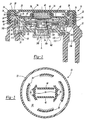
- Figure 1 is a cross-sectional view of a coolant container cap assembly, generally indicated at 10, and a coolant container, generally indicated at 12, both of which are manufactured in accordance with the principles of the present invention.
- the cap assembly 10 is shown mounted to the coolant container 12.
- the coolant container 12 of the present invention is preferably an expansion bottle or surge tank which is in fluid communication with a vehicle radiator. Accordingly, the coolant container cap assembly 10 is preferably a surge tank cap which seals any liquid coolant within the surge tank.
- the coolant container 12 may be any type of fluid container having any suitable design or configuration.
- the cap assembly 10 includes a plastic exterior cover 14 having an exterior surface 16 constructed and arranged to be manually engaged for placement and removal of the cap assembly 10 in covering relation with respect to a main opening 18 of the container 12.
- the cover 14 comprises a circular wall portion 20 and a cylindrical wall portion 22 extending downwardly from the periphery of the circular wall portion 20.
- the interior surface of the cylindrical wall portion 22 is provided with threads 24 which are adapted to cooperate with exterior threads 26 of a container neck 27 surrounding the opening 18 to enable the cap assembly 10 to be secured to the container 12.
- a pair of spring mounting elements 40 which extend downwardly in parallel spaced relation.
- the mounting elements 40 extend transversely between the pair of pawl elements 34 and serve to engage opposite sides of a metal compression spring 42.
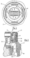
- the ends of the spring 42 engage the pawl elements 34 and serve to resiliently bias the same radially outwardly such that teeth 36 engage with ratchet teeth 44 of a plastic disk-shaped ratchet plate 46.
- the valve housing 50 includes an upper housing portion 56 and a lower housing portion 58.
- the upper housing portion 56 and lower housing portion 58 create a unitary valve housing member 50 formed of a polymeric material.
- the upper housing portion 56 includes a radially outwardly facing annular groove 62 which is constructed and arranged to receive the ledge 30 of the securement tabs 28. This inter-engagement between the tabs 28 and the groove 62 serve to secure the cover 14 to the valve housing 50 while permitting relative rotation therebetween about a longitudinal axis A of the cap assembly 10.
- An adjustment device 70 is associated with the upper housing portion 56.
- the upper housing portion 56 includes an annular flange portion 66 defining a downwardly facing annular flat surface 68, which, as will be described in greater detail later, serves as a support or back surface for the adjustment device 70.
- the adjustment device 70 is an annular corrugated metal spring member 70.
- annular ridge 74 Disposed radially inwardly from the flange portion 66 of the upper housing portion 56 is an annular ridge 74 which is ultrasonically welded to the underside along the periphery of the ratchet plate 46.
- a radially outwardly extending annular projection 78 is disposed on the upper housing portion 56 below the flange portion 66, the function of which will be described in greater detail later.
- the upper housing portion 56 comprises a plurality of axially extending passages 84 disposed in circumferentially spaced relation about the axis A. Two of such passages 84 can be seen in Figure 1.
- the upper housing portion 56 further comprises a plurality of upwardly extending circumferentially spaced tabs 86 having a radially inwardly facing groove 88. Extending radially inwardly from the groove 88 is an annular seat 90.
- the seat 90 has an upper surface 92 which is slightly inclined so as to extend slightly upwardly as it extends towards the central axis A.
- the lower housing portion 58 defines a central aperture 100 in the valve housing 50.
- An annular plastic spring support member 102 seats in fixed relation on the interior surface of the central aperture 100.
- the lower housing portion 58 has a radially outwardly extending annular groove 110 within which a first sealing gasket 112 can be placed.
- the first sealing gasket 112 selectively engages and seals the cap assembly 10 with a first sealing ridge 114 surrounding the opening 18 in container 12.
- the aforementioned spring support member 102 provides a lower support to a metal coil spring member 106 received within the central aperture 102.
- the vacuum plate valve 52 rest upon the upper portion of the coil spring 106 and is biased in an upper axial direction by the coil spring 106.
- the vacuum plate valve 52 has a peripheral annular flange 116, the upper surface of which is constructed and arranged to sealingly contact the underside of a valve gasket 120 towards the radially inner portion thereof. The radially outer portion of the underside of valve gasket 120 engages in sealing relation to the upper surface 92 defined by the seat 90.
- the pressure plate valve 54 has an annular flange portion 121 along the general periphery thereof which is constructed and arranged to engage the upper surface of valve gasket 120 in sealing relation. More specifically, a coil spring member 122 biases the pressure plate valve 54 downwardly so that the flange 121 forms sealing contact with the valve gasket 120.
- the coil spring 122 is disposed in surrounding relation with respect to a central aperture 126 in the pressure plate valve 54. It can be appreciated that coil spring 122 is of greater strength than coil spring 106 so that gasket 120 is normally in sealed relation with surface 92.
- the upper end of the coil spring 122 is supported by a metal spring support plate 130, the periphery of which is received within the annular groove 88 of the upper housing portion 56.
- the spring support plate 130 also has a central aperture 132.
- the cooling cap assembly 10 includes a second annular sealing gasket 140, which is preferably made of rubber.
- the second sealing gasket 140 is disposed above and displaced radially outwardly from the first sealing gasket 112.
- the second sealing gasket 140 is biased downwardly away from the flat surface 68 of the flange portion 66 by the adjustment device 70 to selectively engage and seal the cap assembly 10 with a second annular sealing ridge 142 surrounding the main opening 18 of the container 12.
- the second sealing ridge 142 is disposed above and displaced radially outwardly from the first sealing ridge 114 whereby the first 114 and second 142 sealing ridges are substantially in alignment with the corresponding first 112 and second 140 sealing gaskets.
- the first 114 and second 142 sealing ridges are annular bumps extending upwardly for engagement with a corresponding sealing gasket 112, 140.
- the adjustment device 70 is preferably a corrugated annular spring member 70. Disposed between the second sealing gasket 140 and the spring member 70 is a rigid annular pressure ring 144 which is constructed and arranged to evenly distribute the force from the spring 70 throughout the second sealing gasket 140.
- the adjustment device 70 may be of any suitable design or configuration so long as the second sealing gasket 140 is biased toward a second sealing ridge 142 of a container 12. In fact, as defined by the scope of the appending claims, it is contemplated that the adjustment device 70 may not be mounted to the flange portion 66 or in direct contact with the second sealing gasket 140.
- the container 12 comprises a liquid container portion 150, a vapor container portion 152, and a transition container portion 154.
- the liquid container portion 150 is sealed from the external environment when the coolant cap assembly 10 is disposed in sealing relation with respect to the main opening 18 of the container 12.
- the first sealing gasket 112 in conjunction with valve housing 50, vacuum plate 52, and valve gasket 120 seal the liquid container portion 150 from the external environment.
- the transition container portion 154 has an upper passageway 156 which is disposed in fluid communication with the passages 84 in the valve housing 50 when the cap assembly 10 is secured onto the container 12.
- the passageway 156 is disposed within the container neck 27 of the container 12 between the first 114 and second 142 sealing ridges.
- a channel 148 is disposed between the opening 18 of the container 12 and the passageway 156.
- the channel 148 has an open condition with the first sealing gasket 112 detached from the first sealing ridge 114 and a closed condition with the first sealing gasket 112 engaged with the first sealing ridge 114.
- the channel 148 allows any fluid within the container 12 to pass through the opening 18 and into passageway 156 or vise versa.
- the second sealing gasket 140 remains in sealing contact with the second sealing ridge 142.
- the passageway 156 and the passages 84 in the valve housing 50 are confined to an intermediate space which is neither in fluid communication with the atmosphere or with the liquid container portion 150.
- the second sealing gasket 140 prevents fluid communication with the atmosphere.
- the vacuum and pressure valve plates 52, 54 and the first sealing gasket 112 prevent fluid communication with the liquid container portion 150.
- the top of the transition container portion 154 is in fluid communication with the passageway 156 and the bottom of the transition container portion 154 is disposed in fluid communication with the vapor container portion 152, which itself is vented to the atmosphere.
- the transition container portion 154 provides an area (not specifically shown) within which liquid traveling downwardly therethrough transitions into vapor prior to its travel to the vapor container portion 152.
- the liquid and vapor contained in the liquid container portion 150 is sealed therein by the coolant cap assembly 10.
- the liquid vapor then is permitted to travel downwardly through the passages 84 in the valve housing 50 and then downwardly through the passage 156 into the transition container portion 154, and then into the vapor container portion 152 and then to the atmosphere.
- the second sealing gasket 140 prevents the hot liquid vapor from escaping directly to the atmosphere through the cooling cap assembly 10 during this operation.
- the pressure within the liquid container portion 150 can always be maintained within a predetermined range as predetermined by the force applied by springs 106 and 122.
- the cap assembly 10 can be removed from container 12 without any hot vapors being discharged from the periphery or any other portions of the cap during the initial unsealing operation.
- the cap assembly 10 is unscrewed by rotating the cover 14 in a counter-clockwise direction so that the threads 24 thereof ride upwardly along threads 26 of the neck 27 of the container 12.
- the securement tabs 28 lift the valve housing 50 by virtue of the interengagement of the tabs 28 within the annular groove 62 of the valve housing 50.
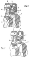
- the first sealing gasket 112 is brought upwardly out of engagement with the first sealing ridge 114 of the container 12, thus permitting hot vapors to escape around the periphery of the first sealing gasket 112. The hot vapors then progresses downwardly through the passage 156, into the transition container portion 154, into the vapor container portion 152, and then vented safely to the atmosphere.
- the cantilevered pawl elements 34 and the ratchet teeth 44 are constructed and arranged to transmit torque movement manually applied to the outer cover 14 in an unscrewing direction to move the valve and sealing assembly 48 out of the closing or sealed position.
- the pawl elements 34 and ratchet teeth 44 also transmit torque movements manually applied to the exterior cover 14 in a screwing direction to move the valve and sealing assembly 48 towards the closing or sealed position in a manner which includes overriding movements therebetween, preventing torque transmittal therebetween above a predetermined value to thereby determine when the valve and sealing assembly 48 has reached the closing position and the desired extend of axial compression imparted to the first sealing gasket 112.
Landscapes
- Engineering & Computer Science (AREA)
- Chemical & Material Sciences (AREA)
- Combustion & Propulsion (AREA)
- Mechanical Engineering (AREA)
- General Engineering & Computer Science (AREA)
- Closures For Containers (AREA)
- Valve Housings (AREA)
- Table Devices Or Equipment (AREA)
- Piezo-Electric Or Mechanical Vibrators, Or Delay Or Filter Circuits (AREA)
- Sampling And Sample Adjustment (AREA)
Abstract
Description
Claims (20)
- Assembly of a coolant container cap assembly (10) and a coolant container (12), said coolant container (12) having first (114) and second (142) sealing ridges, said assembly comprising;characterized by said cap assembly (10) having an adjustment device (70) associated with said upper housing portion (56) to allow relative movement of said first sealing gasket (112) with respect to said second sealing gasket (140), said adjustment device (70) permitting said first sealing gasket (112) to detach from the first sealing ridge (114) of the container (12) while maintaining said sealing engagement of said second sealing gasket (140) with the second sealing ridge (142) of the container (12) when said cap assembly (10) is removed from the coolant container (12)an exterior cover (14) for removeably securing said cap assembly (10) to the container (12),a valve housing member (50) secured to said cover (14) and having a lower housing portion (58) and an upper housing portion (56),a first sealing gasket (112) mounted to said lower housing portion (58) for selectively engaging and sealing said cap assembly (10) with the first sealing ridge (114) of the container (12),a second sealing gasket (140) mounted to said upper housing portion (56) for selectively engaging and sealing said cap assembly (10) with the second sealing ridge (142) of the container (12),
- The assembly as set forth in claim 1 wherein said adjustment device (70) is mounted between said upper housing portion (56) and said second sealing gasket (140).
- The assembly as set forth in claim 2, the cap assembly (10) further including a flange portion (66) disposed on said upper housing portion (56) having a fiat surface (68) with said adjustment device (70) mounted to said flat surface (68).
- The assembly as set forth in claim 3, the cap assembly (10) further including a pressure ring (144) disposed between said adjustment device (70) and said second sealing gasket (140).
- The assembly as set forth in claim 4 wherein said adjustment device (70) is a spring member.
- The assembly as set forth in claim 2 wherein said upper housing portion (56) further includes a projection (78) disposed below said second sealing gasket (140) for limiting downward displacement of said second sealing gasket (140).
- The assembly as set forth in claim 2 wherein said second sealing gasket (140) is disposed above and displaced radially outwardly from said first sealing gasket (112).
- The assembly as set forth in claim 1 wherein said lower (58) and upper (56) housing portions create a unitary valve housing member (50).
- The assembly as set forth in claim 8 wherein said unitary valve housing member (50) is formed of a polymeric material.
- The assembly as set forth in claim 8 wherein said exterior cover (14) is rotatably connected to said valve housing member (50) for allowing said valve housing member (50) to remain stationary while said cover (14) is secured to the container (12).
- The assembly as set forth in claim 10 wherein said valve housing member (50) includes an integrally formed annular groove (62) and said cover (14) includes a plurality of downwardly projecting tabs (28) for engagement with said groove (62) to rotatably connect said cover (14) to said valve housing member (50).
- The assembly as set forth in claims 1 and 11 wherein said cover (14) includes a plurality of threads (24) for engagement with a plurality of corresponding exterior threads (26) on the container (12) to secure said cap assembly (10) to the container (12).
- The assembly as set forth in claim 1 wherein said container (12) for storing fluid has a neck portion (27) defining an opening (18) into said container (12), said opening (18) of said neck portion (27) having said first sealing ridge (114) and said second sealing ridge (142).
- The assembly as set forth in claim 13 wherein said second sealing ridge (142) is disposed above and displaced radially outward from said first sealing ridge (114) whereby said first (114) and second (142) sealing ridges are substantially in alignment with said corresponding first (112) and second (140) sealing gaskets.
- The assembly as set forth in claim 14 wherein said first (114) and second (142) sealing ridges are annular bumps extending upwardly for engagement with a corresponding sealing gasket (112,140).
- The assembly as set forth in claim 13 wherein said neck portion (27) of said container (12) includes a plurality of exterior threads (26) and said cover (14) includes a plurality of corresponding threads (24) for selective engagement with said exterior threads (26) of said container (12) for securing said cap to said container (12).
- The assembly as set forth in claim 13 further including a passageway (156) disposed within said neck portion (27) of said container (12) between said first (114) and second (142) sealing ridges.
- The assembly as set forth in claim 17 further including a channel (148) disposed between said opening (18) of said container (12) and said passageway (156) having an open condition with said first sealing gasket (112) detached from said first sealing ridge (114) and a closed condition with said first sealing gasket (112) engaged with said first sealing ridge (114).
- The assembly as set forth in claim 18 further including a transition container portion (154) in fluid communication with said passageway (156) for allowing fluid to pass therethrough.
- The assembly as set forth in claim 19 further including a vapor container portion (152) in fluid communication with said transition container portion (154) for dispensing fluid passing through said passageway (156) away from said cap assembly (10).
Applications Claiming Priority (3)
| Application Number | Priority Date | Filing Date | Title |
|---|---|---|---|
| US5652297P | 1997-08-21 | 1997-08-21 | |
| US56522P | 1997-08-21 | ||
| PCT/CA1998/000793 WO1999010636A1 (en) | 1997-08-21 | 1998-08-21 | Coolant container cap assembly |
Publications (2)
| Publication Number | Publication Date |
|---|---|
| EP1005606A1 EP1005606A1 (en) | 2000-06-07 |
| EP1005606B1 true EP1005606B1 (en) | 2002-12-11 |
Family
ID=22004962
Family Applications (1)
| Application Number | Title | Priority Date | Filing Date |
|---|---|---|---|
| EP98940017A Expired - Lifetime EP1005606B1 (en) | 1997-08-21 | 1998-08-21 | Assembly of a coolant container cap assembly and a coolant container |
Country Status (8)
| Country | Link |
|---|---|
| US (1) | US6056139A (en) |
| EP (1) | EP1005606B1 (en) |
| AT (1) | ATE229615T1 (en) |
| AU (1) | AU8848698A (en) |
| BR (1) | BR9811315A (en) |
| CA (1) | CA2301117C (en) |
| DE (1) | DE69810118T2 (en) |
| WO (1) | WO1999010636A1 (en) |
Families Citing this family (15)
| Publication number | Priority date | Publication date | Assignee | Title |
|---|---|---|---|---|
| JP4106820B2 (en) * | 1999-07-14 | 2008-06-25 | 株式会社デンソー | Fully sealed container |
| US6763966B2 (en) * | 2000-09-18 | 2004-07-20 | Stant Manufacturing Inc. | Torque-limit signal system for filler neck cap |
| DE20107582U1 (en) * | 2001-05-04 | 2002-09-12 | Reutter, Heinrich, 71336 Waiblingen | Container closure and closure lid of such a container closure |
| DE50207761D1 (en) | 2001-05-23 | 2006-09-21 | Mann & Hummel Gmbh | Container for the coolant of an internal combustion engine |
| US20030094454A1 (en) * | 2001-11-19 | 2003-05-22 | Lambert Wu | Safety valve apparatus |
| FR2851786B1 (en) * | 2003-02-27 | 2005-04-15 | Itw Bailly Comte | COOLING CIRCUIT FOR A MOTOR VEHICLE AND A MOTOR VEHICLE THEREFOR |
| US7216610B2 (en) * | 2003-08-01 | 2007-05-15 | Stant Manufacturing Inc. | Pressure regulator for engine cooling system |
| US7188588B2 (en) * | 2004-11-15 | 2007-03-13 | Mann & Hummel Gmbh | Cooling system and coolant reservoir for a cooling system |
| TWI316908B (en) * | 2005-06-23 | 2009-11-11 | Honda Motor Co Ltd | Tank cap |
| US8038878B2 (en) * | 2008-11-26 | 2011-10-18 | Mann+Hummel Gmbh | Integrated filter system for a coolant reservoir and method |
| FR3000939B1 (en) * | 2013-01-15 | 2015-10-02 | Tristone Flowtech Solutions Tfs | LIQUID TANK AND DEVICE FOR CONTROLLING THE LIQUID PHASE OF A COOLING CIRCUIT OF A THERMAL MOTOR INCORPORATING SUCH A RESERVOIR |
| US9856777B2 (en) * | 2014-12-08 | 2018-01-02 | Toledo Molding & Die, Inc. | Dual chamber coolant reservoir |
| KR101628609B1 (en) * | 2015-03-13 | 2016-06-08 | 현대자동차주식회사 | Pressurization type reservoir tank assembly for cooling water having cover for preventing burns in |
| DE102019115464A1 (en) * | 2019-06-07 | 2020-12-10 | Volkswagen Aktiengesellschaft | Expansion tank for a fluid circuit |
| US12000323B2 (en) | 2022-10-07 | 2024-06-04 | Harley-Davidson Motor Company, Inc. | Coolant filler neck assembly having integrated coolant overflow reservoir |
Family Cites Families (21)
| Publication number | Priority date | Publication date | Assignee | Title |
|---|---|---|---|---|
| US2990971A (en) * | 1959-04-06 | 1961-07-04 | Milton J Enell | Safety closure cap for filling spouts of pressurized liquid cooling systems |
| US2964214A (en) * | 1959-05-08 | 1960-12-13 | Stannard Benjamin Franklin | Pressure radiator cap |
| US3186580A (en) * | 1962-02-07 | 1965-06-01 | Eaton Mfg Co | Closure device |
| US3381846A (en) * | 1966-02-07 | 1968-05-07 | Wells Joe S | Radiator pressure cap |
| US3820680A (en) * | 1972-11-20 | 1974-06-28 | Stant Mfg Co | Torque-limiting device |
| US3937357A (en) * | 1973-09-20 | 1976-02-10 | Tom Mcguane Industries, Inc. | Pressure-vacuum relief fuel filler cap |
| US3878965A (en) * | 1974-05-13 | 1975-04-22 | Stant Mfg Co | Pressure-vacuum relief vehicle radiator cap with free-turning shell |
| US4136795A (en) * | 1975-09-05 | 1979-01-30 | Stant Manufacturing Company, Inc. | Plastic radiator cap |
| US4299102A (en) * | 1979-12-03 | 1981-11-10 | Orion Industries, Inc. | Locking fuel cap with plastic mechanism |
| US4676390A (en) * | 1986-07-22 | 1987-06-30 | Stant Inc. | Pressure-release fuel cap |
| US4767390A (en) | 1987-01-27 | 1988-08-30 | Federal Paper Board Company, Inc. | Apparatus for and method of applying handle to carton closure flap |
| DE3803166A1 (en) * | 1988-02-03 | 1989-08-17 | Laengerer & Reich Kuehler | Pressure relief valve device for the cooling circuit of a liquid-cooled internal combustion engine |
| DE8901826U1 (en) * | 1988-11-23 | 1989-04-06 | Reutter Metallwarenfabrik GmbH, 71336 Waiblingen | Radiator nozzle with cover |
| US5108001A (en) * | 1990-07-03 | 1992-04-28 | Stant Inc. | Pressure release vent cap |
| FR2677001B1 (en) * | 1991-05-29 | 1993-12-03 | Journee Sa Paul | PLUG FOR CLOSING A FILLING TUBE OF A MOTOR VEHICLE RADIATOR. |
| US5114035A (en) * | 1991-10-31 | 1992-05-19 | Epicor Industries, Inc. | Vehicle radiator cap |
| US5169015A (en) * | 1992-02-20 | 1992-12-08 | Stant Corporation | Vehicle radiator cap with auxiliary vacuum seal |
| US5248052A (en) * | 1992-07-31 | 1993-09-28 | Mellinger Larry L | Apparatus for automatically releasing the super-atmospheric pressure of an engine cooling system in response to turning off the engine and preventing the buildup of pressure while the engine is off |
| DE4233038C1 (en) * | 1992-10-01 | 1993-11-25 | Daimler Benz Ag | Overpressure protection for a coolant circuit |
| US5522456A (en) * | 1994-06-22 | 1996-06-04 | Geiger Technic, Inc. | Overflow with threaded plastic fillneck for surge tanks and overflow reservoirs |
| US5603425A (en) * | 1995-03-17 | 1997-02-18 | Western Thomson Controls Limited | Radiator cap |
-
1998
- 1998-08-21 WO PCT/CA1998/000793 patent/WO1999010636A1/en not_active Ceased
- 1998-08-21 AU AU88486/98A patent/AU8848698A/en not_active Abandoned
- 1998-08-21 EP EP98940017A patent/EP1005606B1/en not_active Expired - Lifetime
- 1998-08-21 US US09/138,257 patent/US6056139A/en not_active Expired - Fee Related
- 1998-08-21 CA CA002301117A patent/CA2301117C/en not_active Expired - Fee Related
- 1998-08-21 AT AT98940017T patent/ATE229615T1/en active
- 1998-08-21 BR BR9811315-1A patent/BR9811315A/en not_active IP Right Cessation
- 1998-08-21 DE DE69810118T patent/DE69810118T2/en not_active Expired - Lifetime
Also Published As
| Publication number | Publication date |
|---|---|
| DE69810118T2 (en) | 2003-07-31 |
| WO1999010636A1 (en) | 1999-03-04 |
| BR9811315A (en) | 2000-08-29 |
| ATE229615T1 (en) | 2002-12-15 |
| AU8848698A (en) | 1999-03-16 |
| CA2301117C (en) | 2008-03-25 |
| US6056139A (en) | 2000-05-02 |
| EP1005606A1 (en) | 2000-06-07 |
| DE69810118D1 (en) | 2003-01-23 |
| CA2301117A1 (en) | 1999-03-04 |
Similar Documents
| Publication | Publication Date | Title |
|---|---|---|
| CA2301117C (en) | Coolant container cap assembly | |
| US6755316B2 (en) | Fuel cap | |
| CA2022995C (en) | Fuel tank cap | |
| US5108001A (en) | Pressure release vent cap | |
| US4753262A (en) | Fuel system vent valve having roll-over closure with improved re-opening action for venting | |
| US8430261B2 (en) | Closure cover for tanks under internal pressure, with a safety function, and closure cover for a fuel tank | |
| US4913303A (en) | Liquid splash control fuel cap | |
| US4241845A (en) | Radiator caps | |
| US6701952B1 (en) | Valve and method for fitting it to a tank | |
| JP3550015B2 (en) | Plastic ventilation valve for containers | |
| WO1991003406A1 (en) | Pressure venting closure | |
| CA2255378C (en) | Plastic safety valve for containers | |
| US5507328A (en) | Pouring spout | |
| US20030183632A1 (en) | Closure cap provided with anti-twisting | |
| US4903742A (en) | Liquid dispensing apparatus bottle valve | |
| US7303089B2 (en) | Anti-siphon fuel cap and filler tube assembly | |
| US3715049A (en) | Radiator pressure cap | |
| US7726506B2 (en) | Container closure and closure lid for said container closure | |
| US5603425A (en) | Radiator cap | |
| CA2400891A1 (en) | Pressure cap | |
| US20030150859A1 (en) | Sealing cap | |
| US4090634A (en) | Closure cap for a liquid storing vessel | |
| MXPA00001739A (en) | Coolant container cap assembly | |
| US3516569A (en) | Radiator cap for vehicles | |
| JPH06219461A (en) | Fuel tank cap |
Legal Events
| Date | Code | Title | Description |
|---|---|---|---|
| PUAI | Public reference made under article 153(3) epc to a published international application that has entered the european phase |
Free format text: ORIGINAL CODE: 0009012 |
|
| 17P | Request for examination filed |
Effective date: 20000221 |
|
| AK | Designated contracting states |
Kind code of ref document: A1 Designated state(s): AT DE FR GB IT SE |
|
| 17Q | First examination report despatched |
Effective date: 20001228 |
|
| RTI1 | Title (correction) |
Free format text: ASSEMBLY OF A COOLANT CONTAINER CAP ASSEMBLY AND A COOLANT CONTAINER |
|
| GRAG | Despatch of communication of intention to grant |
Free format text: ORIGINAL CODE: EPIDOS AGRA |
|
| GRAG | Despatch of communication of intention to grant |
Free format text: ORIGINAL CODE: EPIDOS AGRA |
|
| GRAG | Despatch of communication of intention to grant |
Free format text: ORIGINAL CODE: EPIDOS AGRA |
|
| GRAH | Despatch of communication of intention to grant a patent |
Free format text: ORIGINAL CODE: EPIDOS IGRA |
|
| GRAH | Despatch of communication of intention to grant a patent |
Free format text: ORIGINAL CODE: EPIDOS IGRA |
|
| GRAA | (expected) grant |
Free format text: ORIGINAL CODE: 0009210 |
|
| AK | Designated contracting states |
Kind code of ref document: B1 Designated state(s): AT DE FR GB IT SE |
|
| REF | Corresponds to: |
Ref document number: 229615 Country of ref document: AT Date of ref document: 20021215 Kind code of ref document: T |
|
| REG | Reference to a national code |
Ref country code: GB Ref legal event code: FG4D |
|
| REF | Corresponds to: |
Ref document number: 69810118 Country of ref document: DE Date of ref document: 20030123 |
|
| ET | Fr: translation filed | ||
| PLBE | No opposition filed within time limit |
Free format text: ORIGINAL CODE: 0009261 |
|
| STAA | Information on the status of an ep patent application or granted ep patent |
Free format text: STATUS: NO OPPOSITION FILED WITHIN TIME LIMIT |
|
| 26N | No opposition filed |
Effective date: 20030912 |
|
| PGFP | Annual fee paid to national office [announced via postgrant information from national office to epo] |
Ref country code: SE Payment date: 20100812 Year of fee payment: 13 Ref country code: IT Payment date: 20100820 Year of fee payment: 13 Ref country code: FR Payment date: 20100824 Year of fee payment: 13 Ref country code: DE Payment date: 20100818 Year of fee payment: 13 Ref country code: AT Payment date: 20100812 Year of fee payment: 13 |
|
| PGFP | Annual fee paid to national office [announced via postgrant information from national office to epo] |
Ref country code: GB Payment date: 20100818 Year of fee payment: 13 |
|
| REG | Reference to a national code |
Ref country code: SE Ref legal event code: EUG |
|
| GBPC | Gb: european patent ceased through non-payment of renewal fee |
Effective date: 20110821 |
|
| REG | Reference to a national code |
Ref country code: FR Ref legal event code: ST Effective date: 20120430 |
|
| PG25 | Lapsed in a contracting state [announced via postgrant information from national office to epo] |
Ref country code: IT Free format text: LAPSE BECAUSE OF NON-PAYMENT OF DUE FEES Effective date: 20110821 |
|
| REG | Reference to a national code |
Ref country code: DE Ref legal event code: R119 Ref document number: 69810118 Country of ref document: DE Effective date: 20120301 |
|
| PG25 | Lapsed in a contracting state [announced via postgrant information from national office to epo] |
Ref country code: GB Free format text: LAPSE BECAUSE OF NON-PAYMENT OF DUE FEES Effective date: 20110821 Ref country code: FR Free format text: LAPSE BECAUSE OF NON-PAYMENT OF DUE FEES Effective date: 20110831 |
|
| REG | Reference to a national code |
Ref country code: AT Ref legal event code: MM01 Ref document number: 229615 Country of ref document: AT Kind code of ref document: T Effective date: 20110821 |
|
| PG25 | Lapsed in a contracting state [announced via postgrant information from national office to epo] |
Ref country code: AT Free format text: LAPSE BECAUSE OF NON-PAYMENT OF DUE FEES Effective date: 20110821 |
|
| PG25 | Lapsed in a contracting state [announced via postgrant information from national office to epo] |
Ref country code: SE Free format text: LAPSE BECAUSE OF NON-PAYMENT OF DUE FEES Effective date: 20110822 |
|
| PG25 | Lapsed in a contracting state [announced via postgrant information from national office to epo] |
Ref country code: DE Free format text: LAPSE BECAUSE OF NON-PAYMENT OF DUE FEES Effective date: 20120301 |